CSPS Smart Power Supply
Project References:
【wuyu无语】Huawei 460W_CSPS Power Supply_esp8266 Smart (?) Power Supply Board - JLCPCB EDA Open Source Hardware Platform (oshwhub.com)
ATX Power Plan - JLCPCB EDA Open Source Hardware Platform (oshwhub.com)
ATX Power Plan Interface Adapter - JLCPCB EDA Open Source Hardware Platform (oshwhub.com)
GitHub - hitsword/csps_esphome: CSPS Power Supply PMBUS For ESPHome
GitHub - KCORES/KCORES-CSPS-to-ATX-Converter: Super ATX Power!
ESP8266 Pin Usage Notes and Recommendations - Zhihu (zhihu.com)
I. Project Overview
The project includes:
Power interface board (ATX3.0)
Core board (ATX3.0)
II. Detailed Introduction
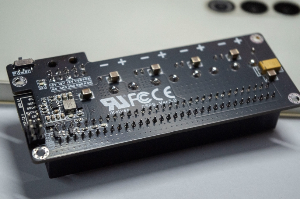
1. Power Interface Board (ATX3.0)
It adopts a Noguchi 64P input, 4 XT60PW-F and MX3.0-10P (ATX3.0 standard) outputs.
The DC-DC main controller uses TPS563201DDCR, SMF3.3A (or ZMM3V3) for overvoltage protection
, 2N7002 for I2C level conversion, and
ESP8266 (ESP-12F or... ) After the ESP-12E is linked with Home Assistant, it can be remotely started and its voltage, current, power, efficiency, and
other data can be read in real time. More power data can be read through custom register addresses.
Compatible power supplies: EPW750-12A, PS-2751-7H; other power supplies have not yet been tested.
Due to size and cost limitations, the recommended total power of this power board is no more than 600W.
A copper busbar soldering position (6mm (width) * 50mm (length)) has been reserved.
A forced output shutdown function has been added, which requires Home Assistant. Firmware must be flashed to force IO2 to go high; otherwise, the physical switch will not work. See Figure
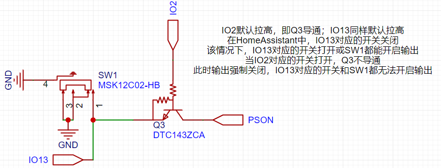
2 for details. Core Board (ATX3.0):
The main circuits of the core board have been windowed.
One PW22ASAB is used for both 5V and 3.3V outputs, and one ZXDN10 is used for 5VSB.
The main control chip is either WT7510 or TPS3510.
III. Postscript:
Because everyone's development environment is different, tutorials on Home Assistant and ESPHOME are not provided. Related tutorials can be found on Bilibili or other platforms.
For firmware flashing of the ESP8266, please prepare a jumper cap and a USB-to-serial adapter module. The silkscreened TX and RX should correspond to the TX and RX of the programmer (the order does not need to be swapped).
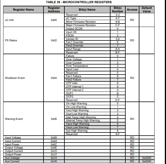
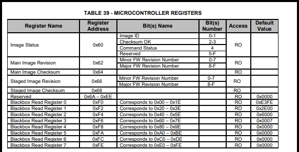
IV. PMBUS I2C Address Reference (PS-2751-7H)

V. Reference Images


flash_download_tool_3.9.5_0.zip
esp-12f_product_specification_zh_v1.0_2.pdf
csps_esphome_code (Ver3.0).zip
csps-power-Ver3.0 firmware.bin
Huawei-EPW750-12A-datasheet.pdf
PS-2751-7H-LF Lite-On 750W Platinum Power Supply Datasheet (VDpdf)
NAK12S20(PW22AS)(1).pdf
Power Supply Compartment Model (SFX Bezel).step
BOM_Power Interface Board (ATX3.0) 2024-09-26.xlsx
PDF_CSPS-ATX12VO Smart Power Supply.zip
Altium_CSPS-ATX12VO Smart Power Supply.zip
PADS_CSPS-ATX12VO Smart Power Supply.zip
BOM_CSPS-ATX12VO Smart Power Supply.xlsx
91139
electronic


 京公网安备 11010802033920号

 2200RA1F50823JA


