Description: This is a unit from a personal home environment smart transformation attempt, based on ESP8266/ESP32 hardware and the MQTT protocol, which I gradually learned from scratch after accidentally falling into the electronics DIY pit. I only stumbled upon this JLCPCB event on September 8th. With limited preparation time and being my first time releasing open source, I was unfamiliar with the process and considered giving up several times due to the hassle. However, I was deeply grateful for the free PCB fabrication policy and the enthusiastic help from JLCPCB's online technical support staff during the EDA software promotion over the past year. I had to persevere, treating it as an assignment and contributing my modest efforts to the collective effort. This is my
first time sharing a project, so there may be omissions; please feel free to offer your guidance.
Hardware Description:
The ESP32C3 performs the core processing functions. The reason for adding external flash memory in this project is that these C3 chips were from last year's first replica project (Smog's charging station). I didn't understand the chip models and was misled by the vendor into using chips without storage. They've been sitting idle, so adding external flash memory is a good idea.
A four-digit LED display shows numbers and time. The TM1650 was chosen simply because when I was preparing to rebuild a complete system for the project, Uxin didn't have the TM1637 chip, so I had to modify the board and use the 1650.
The sound sensor circuit is a ported LM393 sound sensor module.
The temperature and humidity meter is based on the AHT20 chip. The AHT20 manual states that it should have a dedicated I2C channel, while C3 only has one I2C channel, which needs to be shared with the LED display. After testing, there was no noticeable noise in actual use; only an I2C READ error message appeared during system startup (as mentioned earlier, using this chip was a last resort).
The barometric pressure sensor is based on the BMP280. Due to the current usage of I2C channels in this project, a 4-wire SPI working mode was chosen.
A photoresistor was added as a light sensor component. The reason was to avoid adding a photoresistor to each human body sensor light; instead, the goal was to use a central sensing hub to send the light index to all the sensor lights in the home via MQTT.
The buzzer and LED are used for hourly chimes and integer reminders when the jump rope count reaches 100 or 1000.
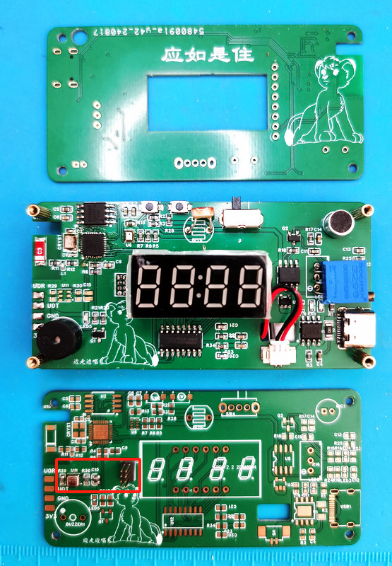
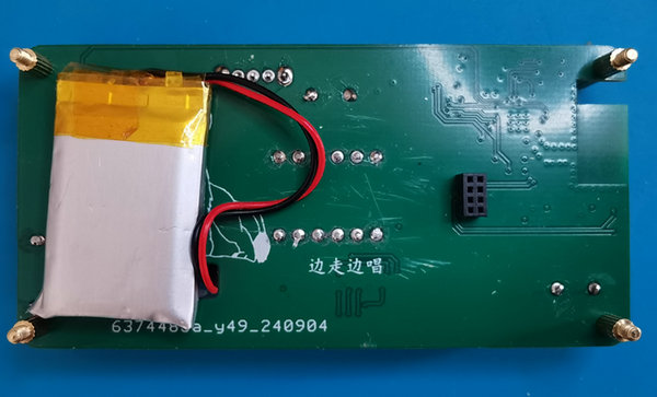
PCB assembly instructions: The entire project requires three boards. The middle board contains all components except for the temperature and humidity sensors; the base board contains the AHT20 chip and related resistors and capacitors, and is pulled out separately to avoid the impact of other components' power consumption and heat dissipation on the accuracy of temperature and humidity sensing, while also forming battery space with the middle PCB; the front panel is for shielding.
Software instructions:
Compiled using VScode + PlatformIO environment
. Deploying your own MQTT server and HA server is recommended for more complete functionality. The reason for learning everything from scratch in both hardware and software is because I deeply dislike the closed ecosystems and self-imposed limitations imposed by manufacturers in the home automation process. My home—can others really dictate its design?
The mobile app can use IoT MQTT Panel_0.45.18_Apkpure.apk and Home Assistant. The former is simpler to integrate, while the latter has a more aesthetically pleasing interface but requires HA server support. (See the illustrations below for interface differences).
Main software functions include:
web-based network configuration, initial startup after firmware installation, on-demand network connection during use, and recovery
in case of startup failure; basic clock display, hourly chime, and a Pomodoro timer
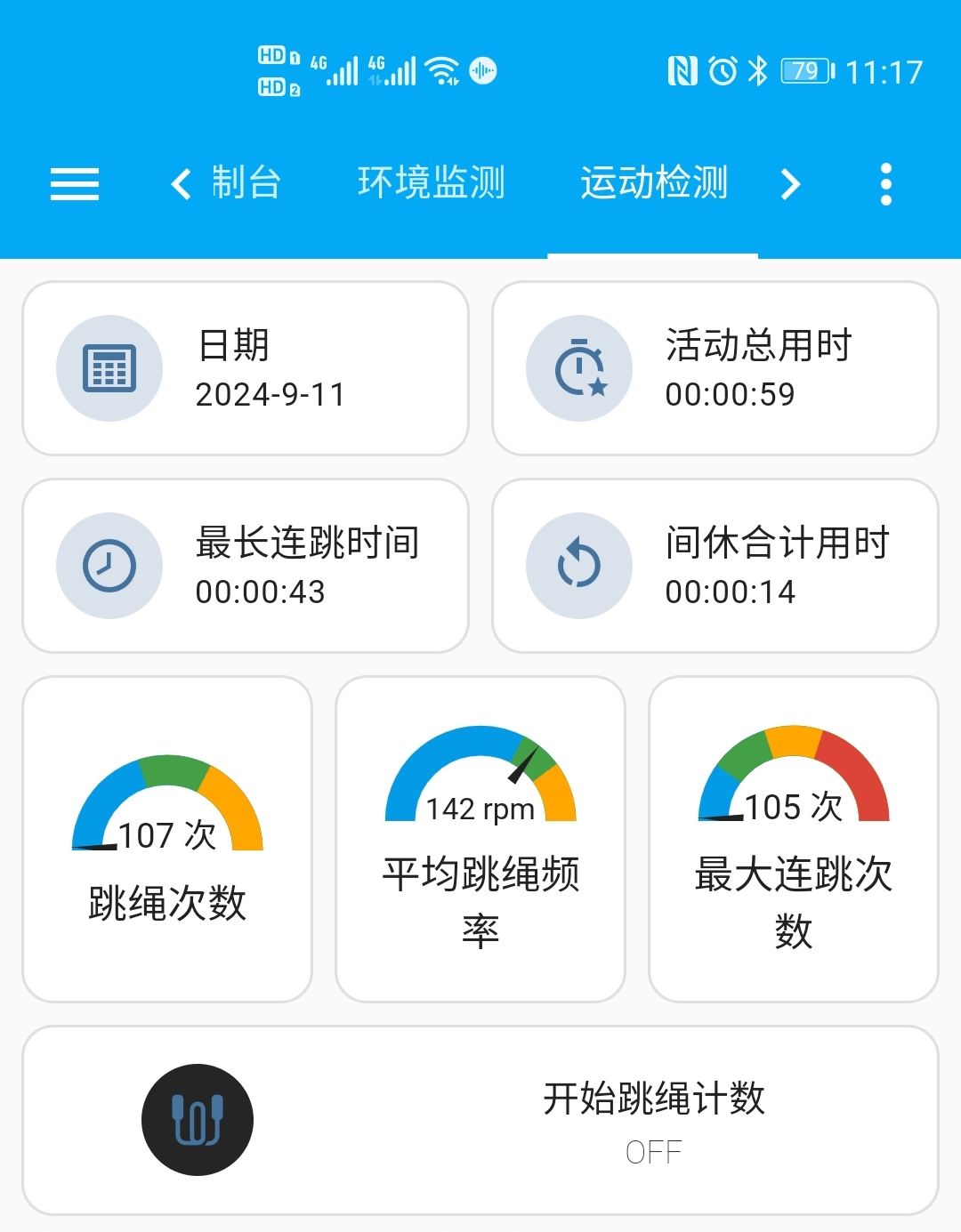
with sound-based jump rope counting; start/stop support for physical buttons and remote protocol control. Basic data statistics and information reporting (total number, actual jump rope time, maximum consecutive jumps and duration, average frequency) facilitate long-term training comparison.
Sound sensor sensitivity can be adjusted via a sliding resistor
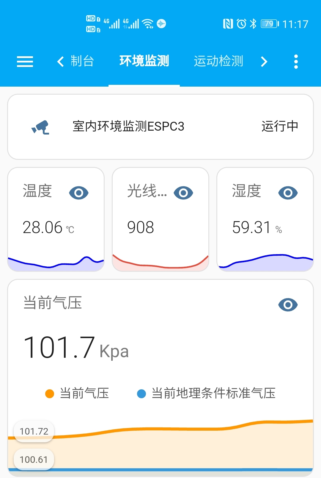
. MQTT is supported, enabling the reporting of environmental sensing data such as temperature, humidity, air pressure, and light intensity via MQTT, displayed through the mobile app, as well as jump rope count statistics. Remote control of the count and Pomodoro timer can also be achieved via the mobile app using the MQTT protocol.
OTA firmware upgrades are supported, allowing for firmware updates via the network.
Supports multiple AP access (I have too many self-made smart terminals, and one AP can no longer provide stable access).
Supports selecting whether network access is required for startup.
Supports Home Assistant MQTT automatic discovery, and can be integrated with MQTT for convenient information display and control.
Component procurement:
There are no particularly special components. Except for the battery and antenna, JLCPCB or Uxin can be purchased in one stop. The price of a single BMP280 chip varies, and I couldn't distinguish between good and bad, so I bought a disassembled module from Uxin.
Component soldering and assembly:
First, solder the middle core board. If using external Flash, it is recommended not to solder the Flash first. After the entire iron plate (excluding through-hole components) is heated, check that the chip soldering is normal and it can start, then manually solder the Flash. Because the space between the Flash and the chip is limited, soldering them together with the ESP chip storage pins makes it difficult to repair if there are problems.
After soldering the Flash, you can connect to the serial port through the reserved test points to burn the firmware. Start the firmware to check if the BMP280 soldering is normal. If the soldering is normal, you can then solder the digital tube, pin header, mic, and other through-hole components normally.
The base plate is heated on a hot plate with the AHT20 and related resistors and capacitors. Since the AHT is a temperature and humidity sensing component, temperature control during soldering has an impact (contact time should be less than 30 seconds at a maximum temperature of 260℃). If you are not confident in your soldering skills, it is recommended to continue with the hot plate heating. After all, a 400W hot plate will only reach a maximum temperature of 250℃; just pay attention to the time.
After soldering, assemble and heat-dry the machine. The AHT requires a hydration process (the sensor should be stored in an environment >75%RH for at least 24 hours to ensure polymer rehydration. Otherwise, the sensor readings will drift. Alternatively, the sensor can be placed in a natural environment (>40%RH) for more than 5 days to allow it to rehydrate). During this period, the measured values will mainly be affected by humidity. This process is strongly recommended. Boards before assembly:
Version iterations:
1. Prototype: ESP01S + digital tube + LM386 module + buzzer
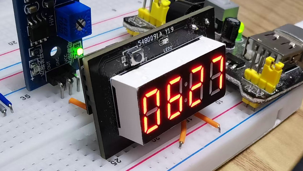
2. Next-generation: ESP01S + digital tube + LM386 module + buzzer + physical control buttons (external GPIO is insufficient, so a wire is run from the chip...)

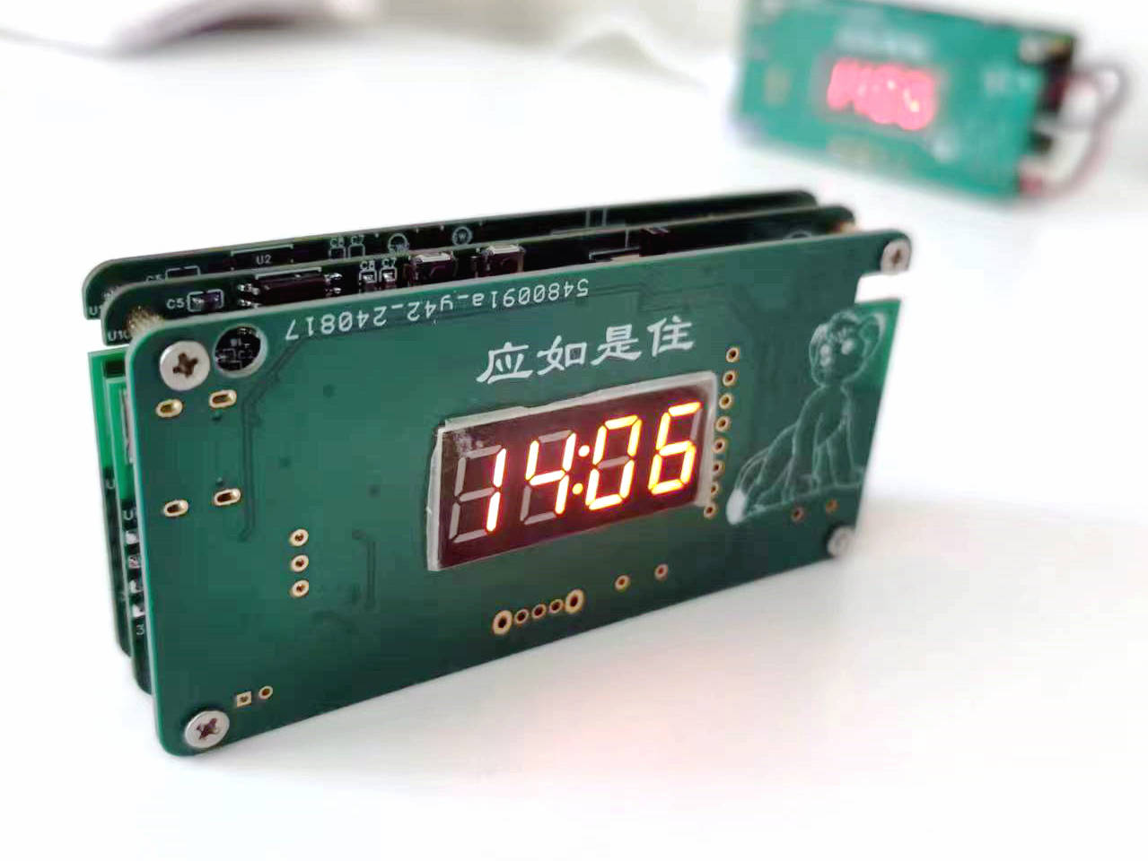
3. Current state (the middle copper pillars have not yet arrived, and the test pin headers have not been removed)
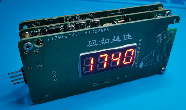
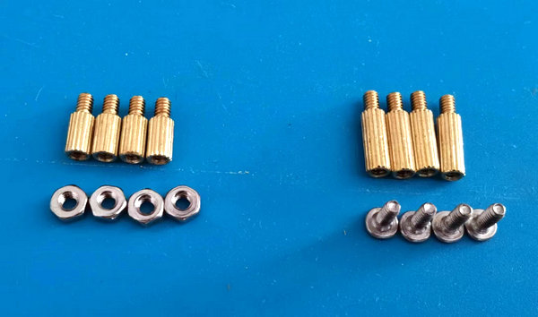
4. Four M2 (8+3) copper pillars connect to the front board and the middle board, and four M2 (5+3) copper pillars connect to the rear board. Considering the pin header connection height between the rear board and the middle board, the longest copper pillars for the rear board and the middle board can only be 8+3, and the pin headers should be pressed down when soldering the rear board pin headers to avoid wasting length.
Assembly complete. Final form after removing the header pins.
Usage effect:
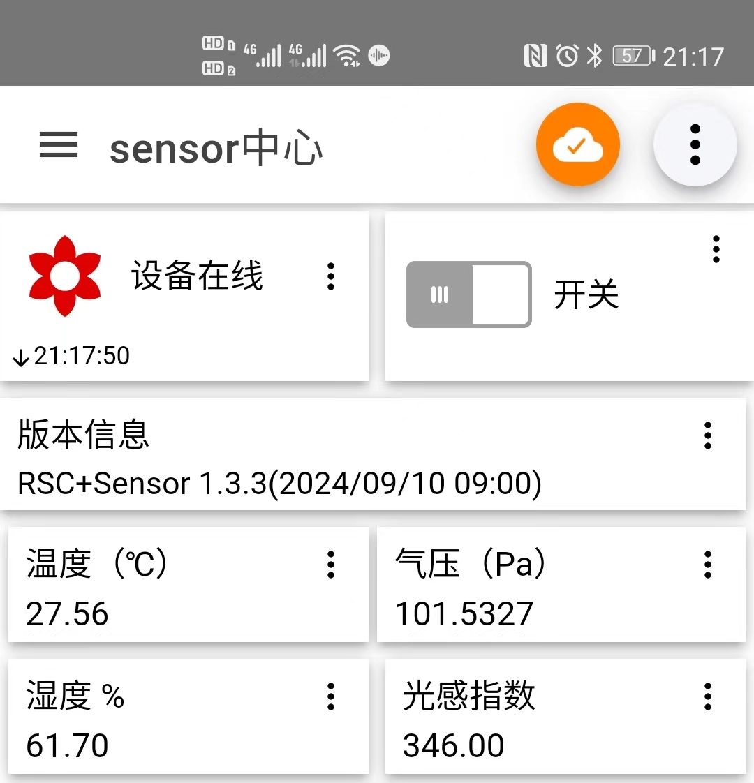
After integration with Home Assistant, the mobile phone display
shows environmental data such as temperature, humidity, and air pressure (comparison between HA client and IoT MQTT Panel).
Finally:
Thank you @JALCIC for your substantial investment in the development and growth of the industry. I believe many beginners like myself have gradually entered the field, learned, and grown with such selfless support. Heartfelt thanks, and sincere hope that JALCIC will continue to thrive, and that our entire electronics industry and everyone within it will prosper.
Thank you @MysteriousTreasureHouse. When I was completely lost and couldn't figure out how to set up a development and compilation environment, and when I was overwhelmed by the various compilation environment options, you enthusiastically helped me, guided me into the field, and pulled me through the most difficult stage of getting into software development. My gratitude will never be forgotten.
Thank you @oldfox126. It was your open-source project on the national standard five-hole metering socket, especially the open-source software, that allowed me to learn how to build a project architecture and how to implement MQTT. Recalling the initial confusion and bewilderment when I first encountered this code, to today being able to digest it and achieve some of my own goals, only I know the extent of this growth. I hope you understand that this growth is due to your selfless help and true open-source spirit.
Thank you @LittleScum for reminding me to cultivate good habits, to leave test points when designing boards, and to avoid digging myself into pitfalls and leave myself room for maneuver. Unfortunately, I listened more than I did, and every time I hastily built the board only to find that my thinking was not comprehensive enough.
Thanks to @yiplay. My use of JLCPCB EDA was entirely based on replicating your ESP32S3 development board project. I think no one, besides yourself, spent more time working on that schematic and PCB layout than me.
Thanks to everyone who helped me; the selfless help of predecessors is the driving force for the growth of successors, and the growth of successors is the best way to repay the help of predecessors. This passing on of help and growth is the inheritance and promotion of the open-source spirit.


 京公网安备 11010802033920号

 15-44-4103


