Welcome to this project.
This project is a simple voltage and current meter based on the LCSC GeoStar development board and modified from the official example. The voltage detection range is 0-34.5VDC, and the current detection range is 0-5.45A.MAX. This is a general DIY project and cannot replace professional equipment and instruments for measurement. No guarantees are made. Use electricity with caution!!!
This project is based on the official example in the following ways:
1. It uses the onboard power supply of the development board, removing the additional power supply circuit.
2. It removes the built-in voltage and current auxiliary calibration circuit.
3. It uses a 4-digit 14-pin 0.56-inch digital tube with a clock.
4. It adds a buzzer circuit.
5. Most of the components are replaced with surface-mount components.
This project is characterized by fewer components, simple construction, and a decent appearance.
This project also plans to add time display, alarm clock, and countdown functions based on the examples in the official voltage and current meter training camp. However, since this is my first time directly dealing with software code, my skill level is limited, and I don't know where to start. It hasn't been implemented yet (I'm too inexperienced!!!), so I can only call it a little bit of a waste.
As
a novice in electronics, I entered this circle many years ago, but due to the limitations of the early DIY environment and work reasons, I only stayed at the level of perforated boards and hand-drawn simple PCBs, or bought boards and soldered them myself for fun. There was no low-cost medium to learn professional design software and knowledge that required in-depth study, so I put it down for a few years. For a hobby that is not related to work, it is really a bit of a pity that I can't fully understand it, and I can't let go of it because I don't have the conditions.
I came into contact with JLCPCB in early 2023. I remember seeing a video on Bilibili about domestic EDA software that could make PCBs for free, so I pulled off the dust cover of interest and tried JLCPCB EDA — and then I was hooked. My first PCB development project was an open-source project by the "veterans" of the LCSC open-source platform. It took me directly from the "1206-level soldering process" before I even left the LCSC platform to the 0402 era (it did take a little effort and a bit of work back then).
I started with no components at all, and now I have several boxes of various types and parameters of my "personal small component library," all stocked up on from the LCSC online store. From not even being able to find component replacements and only being able to buy components according to the BOM using my living expenses, to now scavenging coupons from the online store every month, stocking up on useful, planned, and highly probable components at super low prices, my EXP is definitely ++++! This year, I've also encountered several low-price development board purchase events, such as 1 yuan events, coupons for participating in events, and free gifts for participating in events—how could that not be tempting?
This project was also a learning platform provided by the "Voltage and Current Meter Training Camp" jointly organized by LCSC and Sinyuan Semiconductor. This was the first training camp I participated in. Of course, I'm also very interested in similar training camps in the future. As for buying too many development boards, they'll just gather dust, but whether they do or not depends on your own efforts, haha. In short, I'm very grateful to JLCPCB for providing the "one-stop service," which truly allowed me to improve with very low additional costs. Thank you! Thank you!
Regarding the project ,
this project fully utilizes the development board's pins, simplifying the peripheral circuitry. While achieving its intended functions, it also aims to be truly simple.
As mentioned earlier, it's a simple voltmeter and ammeter with three buttons. The hardware design includes a digital tube with clock display capabilities and a passive buzzer. It can use the chip's built-in RTC and timer to implement clock, alarm, and countdown functions without power interruption (provided there's no power outage, otherwise I'd have to start over... and my software skills are poor, I don't know how to code, so it's not implemented yet). Two LEDs with opposite positive and negative terminals can be used with PWM to light them separately. Additionally, a set of communication interfaces is provided, allowing for programming using four-wire SPI, I2C, and serial ports. It can also connect an external RTC with a button battery to achieve a clock that doesn't stop even when the power is off. Once my technical skills improve, I'll definitely put it to use.
The project utilizes JLCPCB EDA for everything from PCB design and casing to panel and vibrant color silkscreen printing. For beginners, JLCPCB EDA is indeed easy to learn and complete simple tasks, as it only requires a webpage. Of course, it's not impossible to do complex projects; if it were, no beginner would jump straight into a complex project, and experts wouldn't bother with simple ones.
Schematic:

The core board of this JLCPCB Diwenxing design uses the CW32F030C8T6 microcontroller from Wuhan Xinyuan Semiconductor. Its ADC is a true 12-bit (4096 levels) successive approximation analog-to-digital converter (SAR ADC) with a maximum conversion speed of 1M SPS, capable of converting up to 16 analog signals to digital signals. The design
divides voltage sampling into two paths: one uses a 27K resistor and a 10K resistor for voltage division, sampling from 0-4V (the official example uses two 10K resistors for voltage division, sampling from 0-3V); the other uses a 220K resistor and a 10K resistor for voltage division, sampling from 4V to 34.5V. However!!! The official final code only uses the high-range channel and does not include low-range detection. I tried to add it, but it worked strangely... So I compromised. Therefore, the circuit for the first channel (ADC_IN9) can be ignored and not soldered.
The current sampling is a 100mΩ 2512 package resistor with a maximum power of 3W. Theoretically, a 3W resistor can detect a maximum current of about 5.45A. Note that the standard usage of the ammeter is to connect it in series with the circuit being tested. Since the current and voltage ranges share GND, the negative terminals of the two ranges cannot be used simultaneously at two different reference points in the same circuit, nor can they be used simultaneously at non-grounded points in different circuits, to avoid short circuits and unexpected loops. When using them simultaneously in a circuit with the same ground point, pay attention to the polarity of the probes and do not reverse them: the current range requires a larger area of copper foil to carry the current, while the GND lead of the voltage range is thinner. The voltage range can use the negative terminal of the current range, but the current range cannot use the negative terminal of the voltage range.
For the voltage and current sampling circuit, the official example uses a 1N4148 to clamp the system voltage to 5V at the ADC pin for overvoltage protection. However, this project uses surface-mount components, and we were concerned that using a 1N4148 in an SOD123 or smaller package would result in a higher voltage drop compared to through-hole components. Therefore, the 1N4148 was omitted, and an SMF3.3TVS diode was used for reverse clamping to ground. Since the current in the sampled circuit is relatively small, the measured overvoltage clamping was kept below 4V.
The schematic includes a TL431 2.5V voltage reference circuit. Since the CW32F030C8T6 has built-in 2.5V and 1.5V voltage references, and the software uses the internal 1.5V reference, this part of the circuit can be omitted (saving several components).
PCB:
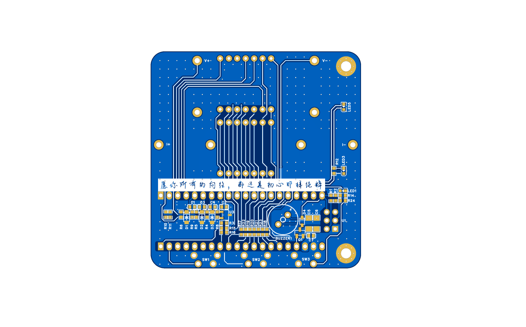
Color silkscreen effect:


The color silkscreen design is relatively simple, with a slight blue-white gradient as the background, orange component silkscreen, and blue component references. This was mainly because it was the first time using JLCPCB color silkscreen, and we wanted to see the two large colored logos.
3D Shell:

This shell corrects several errors from the first version and modifies some solid and slotted areas. Since I don't have a 3D printer, I'll have to bring it with me next time I go to LCSC's 3D printing shop to see if it's suitable.
Panel:
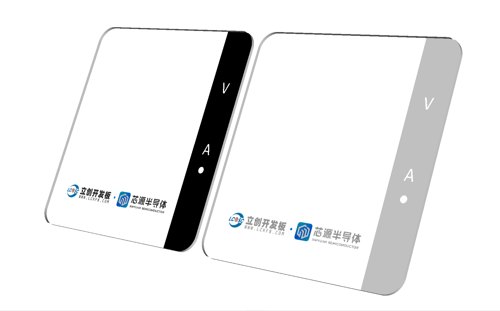
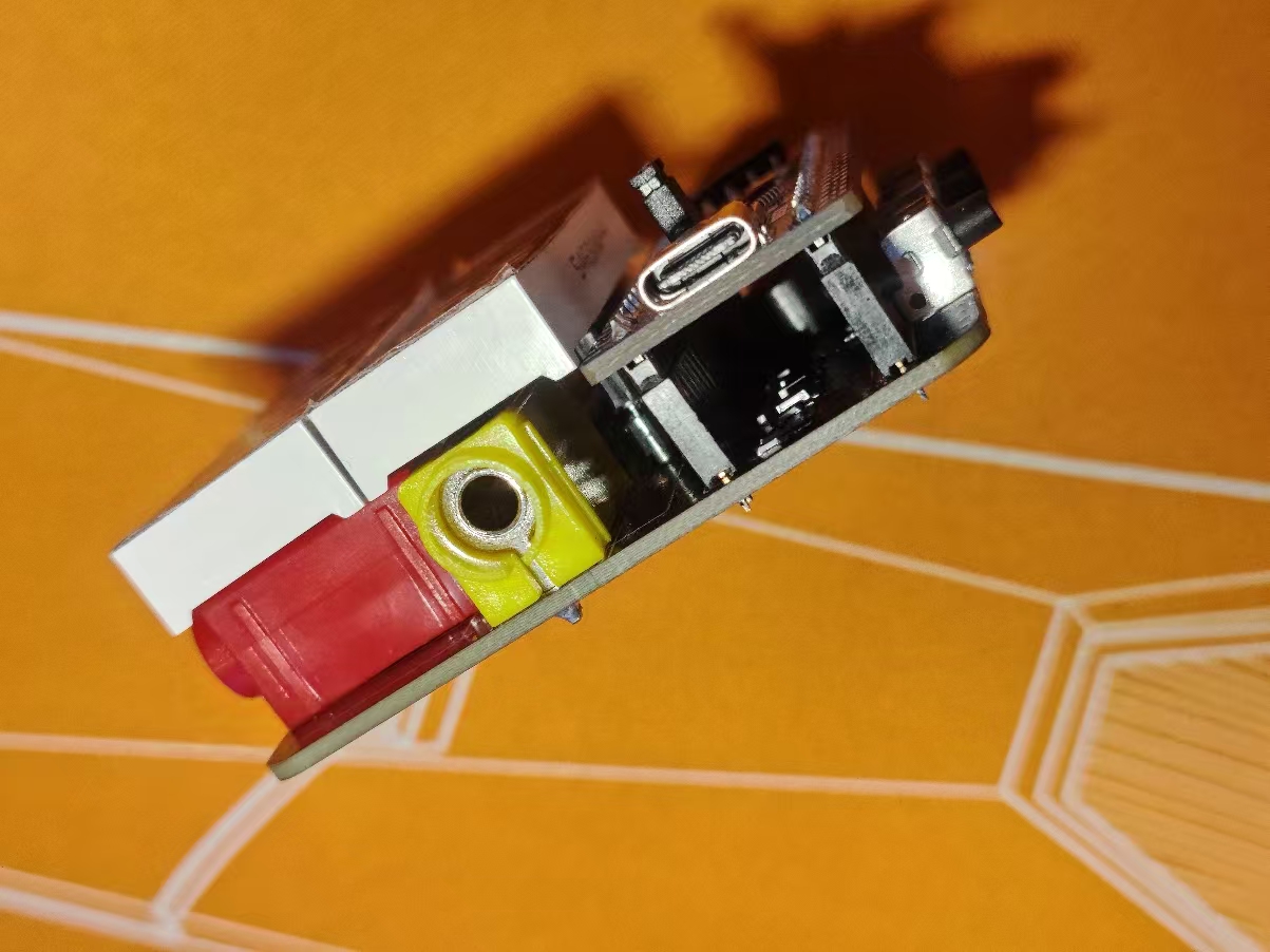
The panel uses 1.5mm thick black semi-transparent acrylic with printing on the bottom and a backlit digital display. The panel's strength is good; I estimate 1mm thickness would be sufficient... (just guessing). The banana head
mounts
are 4mm horizontal, taking up most of the space.

To differentiate voltage and current settings, the current setting uses yellow for the positive terminal and black for the negative; the voltage setting uses red for the positive terminal and blue for the negative. This model has limited color options on the LCSC online store, and the price is quite high, so I used pictures to search for and purchase the same model on a shopping platform.

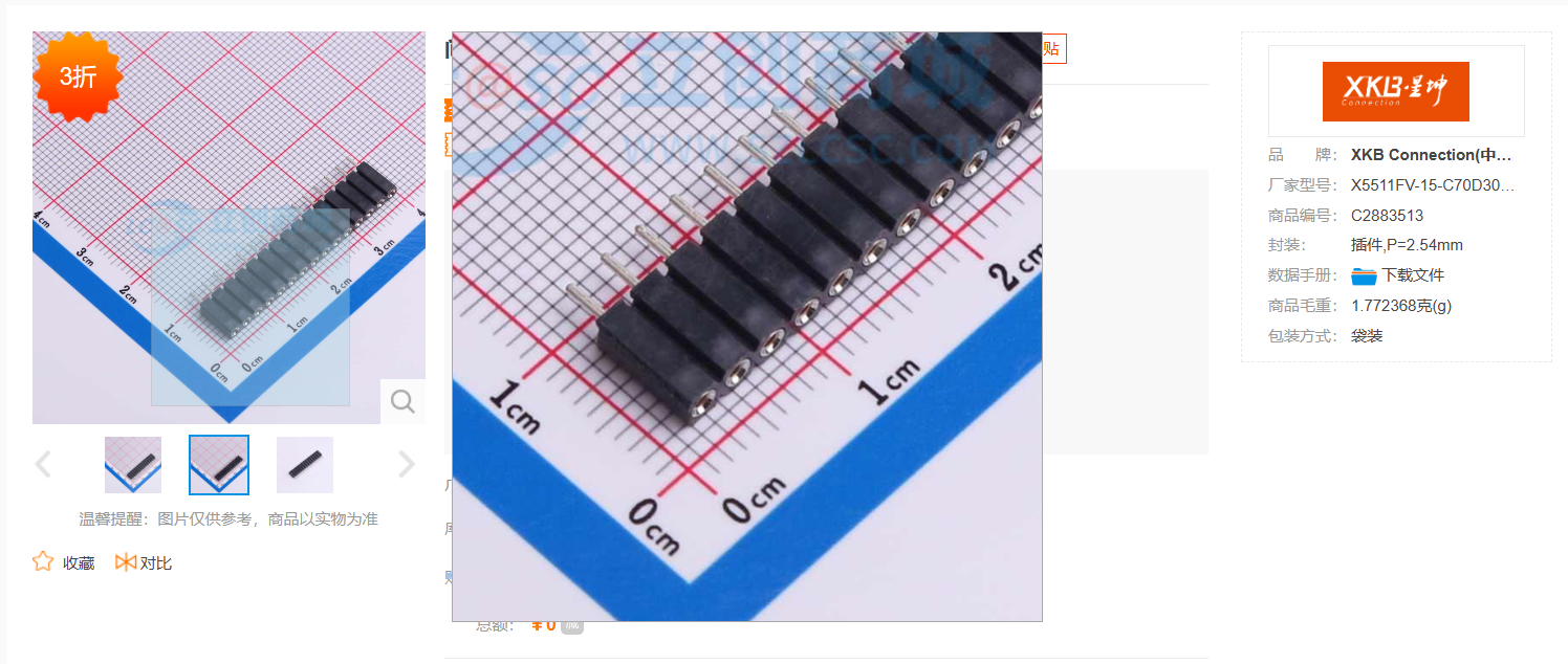
The 0.56-inch 4-digit common cathode LED display uses a 14-pin common cathode LED display with a clock indicator that can also illuminate the decimal point. Actually, it's compatible with common 12-pin common cathode LED displays without a clock indicator (if it's a 12-pin display with a clock indicator, the decimal point won't light up). The rightmost pin of the two rows of pins on the 14-pin display is the clock pin; ignore these two pins when using a 12-pin common cathode display). Because the banana-head connector and the 0.56-inch LED display take up a lot of space, to maximize space utilization, each row of LED pins uses two rows of 7mm high round hole sockets (square holes are not used because the LED pins are round and slightly thinner; testing showed that square hole sockets would cause poor contact).
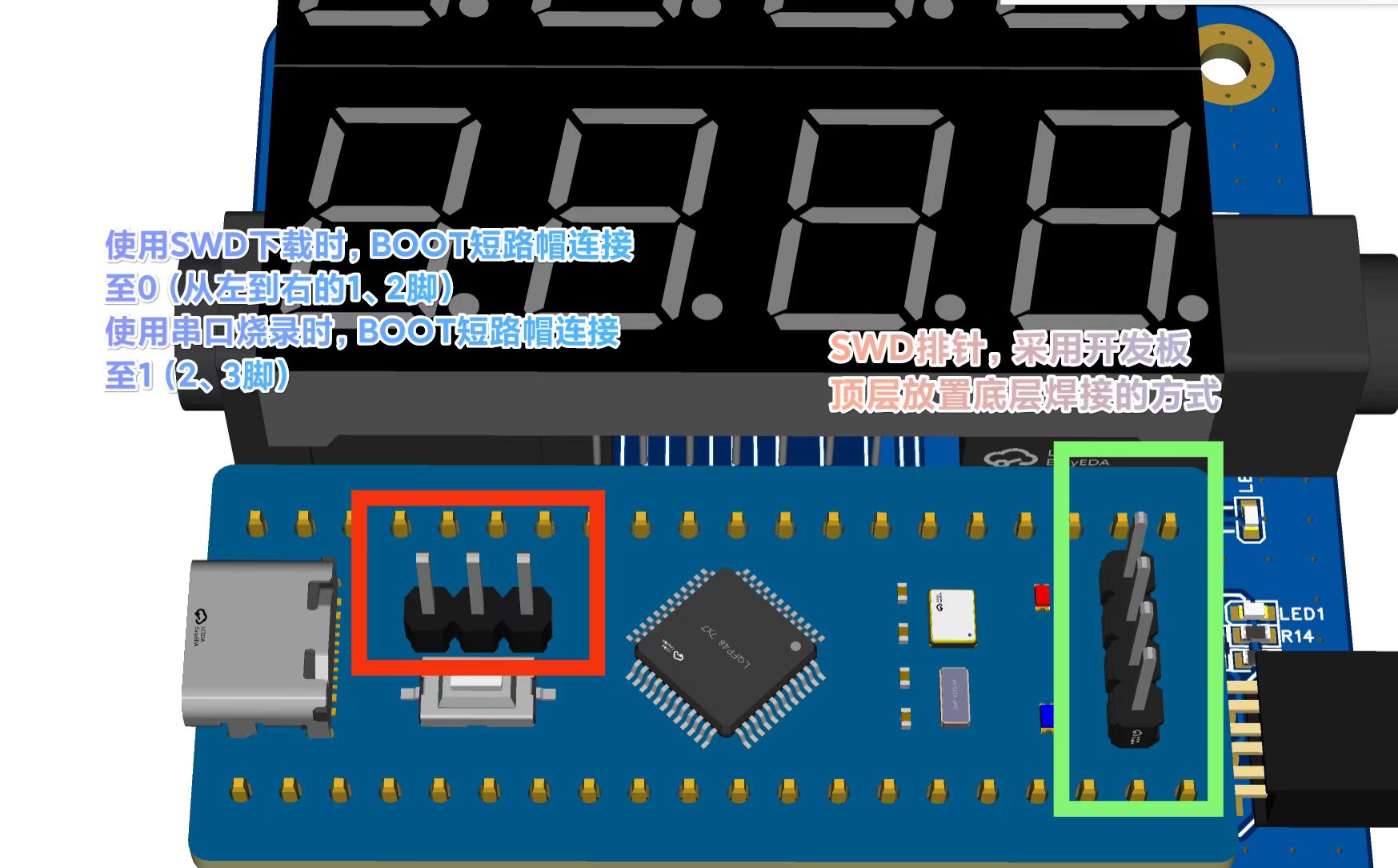
The SWD header is placed on the top layer of the development board and soldered on the bottom layer. This SWD interface can also be used for serial programming. When using SWD and serial programming, pay attention to the position of the BOOT shorting cap.
The PCB uses two rows of 1x20P 8.5mm high square hole socket headers to mount the development
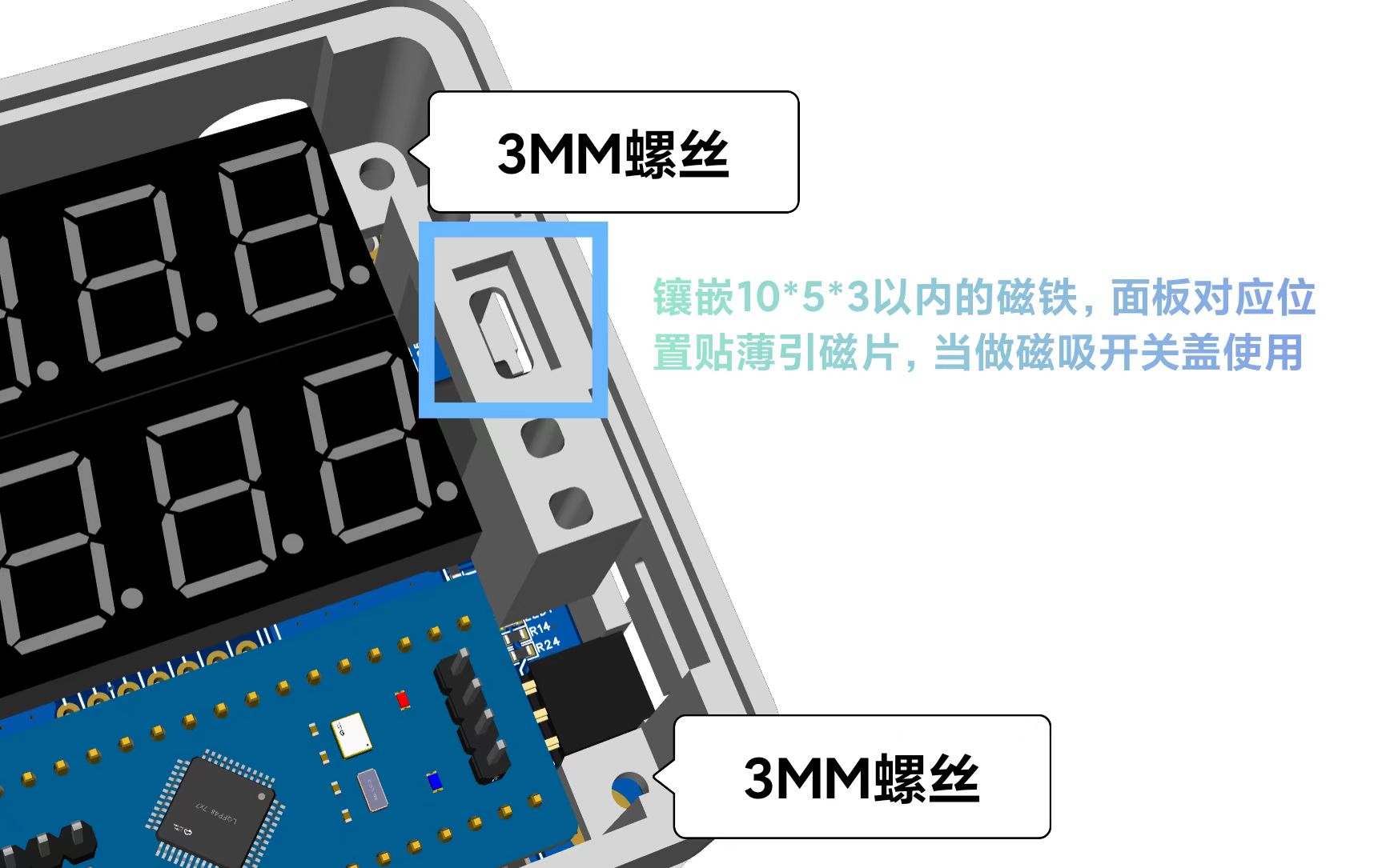
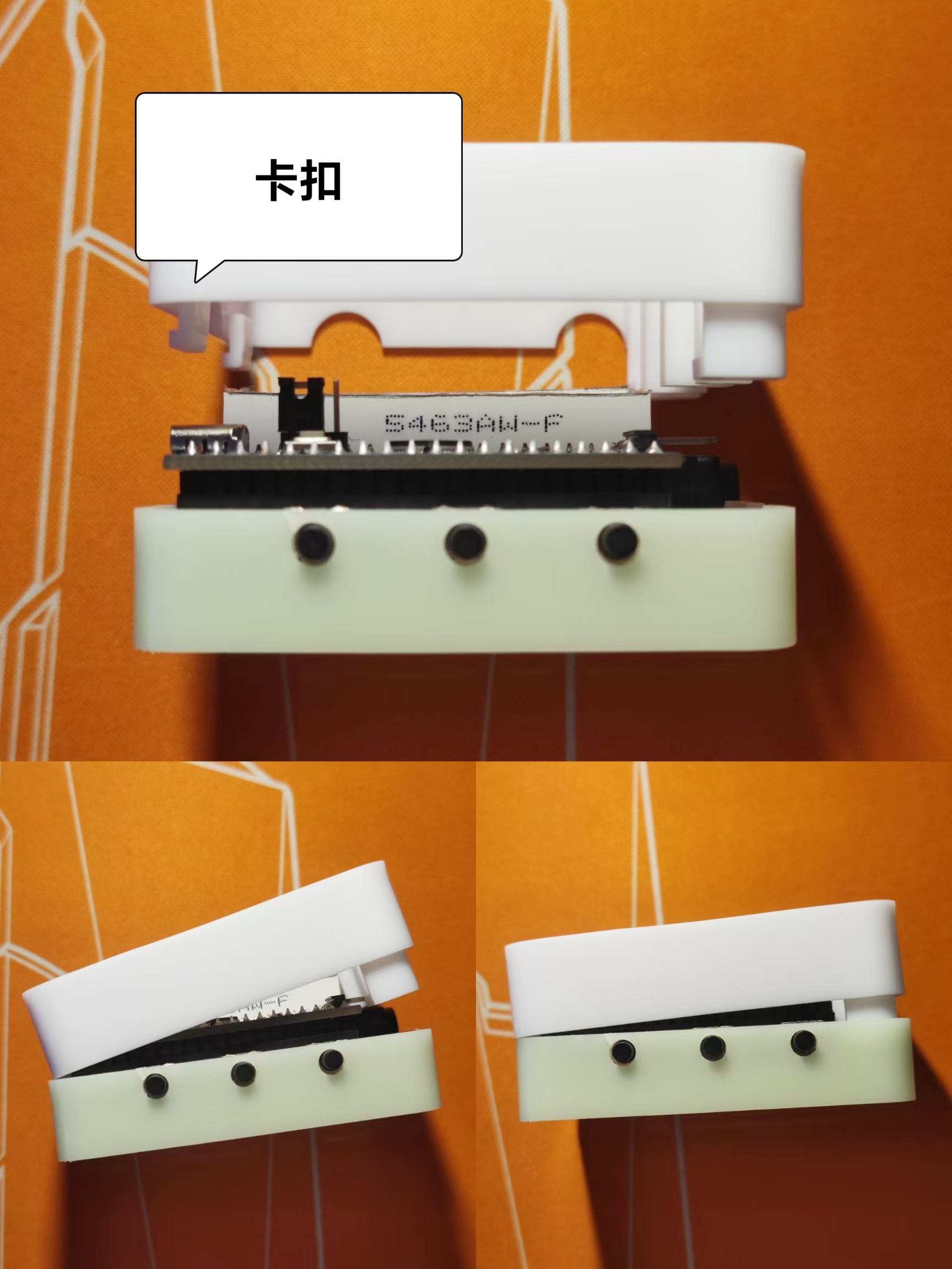
board The upper and lower shells are secured with clips on one side and screws with a diameter of 3mm and a length of 5mm-8mm on the other. During installation, after inserting the board into the bottom shell, insert the top cover clips into the left side gap, press down the right side, and then screw in the screws. It is recommended to use magnetic attachment for the panel mounting or apply adhesive backing after debugging. When using magnetic attachment, it is preferred to use cuttable soft magnetic strips. Apply magnetic strips with a total thickness of no more than 5mm to the right-side mounting area and the corresponding position on the panel. Alternatively, you can embed magnets no larger than 10mm x 5mm x 3mm with a magnetic attractor, keeping the total thickness within 5mm. When using adhesive backing, apply adhesive only to the edge within 1.5mm after debugging (because the RST button on the board is used during debugging, and constantly unplugging and replugging the power button is too inconvenient).
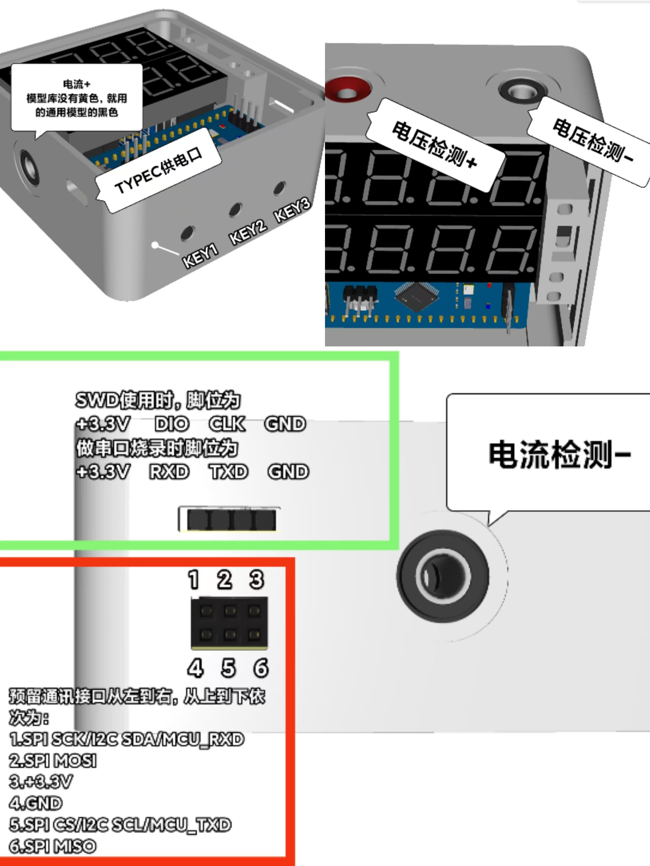
Note that the pin definitions for the communication reserved interface are presented intuitively here, differing from the pin assignments shown in the component manufacturer's package diagram (here, the pins are arranged horizontally facing the female connector, whereas the manufacturer's pin order follows the package standard).
Voltage and current calibration
can be performed directly after the first program flash and power-on, or calibrated before use. If only 5.0 or 0.5 is displayed and the numbers remain unchanged, calibration is required before use. Be careful not to press KEY1 and KEY2 keys randomly to avoid accidental calibration errors! The three keys, from left to right, are KEY1, KEY2, and KEY3. If calibration is required, press KEY1 to enter calibration mode. When S.0.5 is displayed, the calibration is 5V. Use the multimeter probes to measure a precise 5.00V power supply (such as an adjustable power supply set to 5.00V output). Then press K2 to complete the calibration. The microcontroller will set the currently acquired voltage to the 5V standard. If a voltage other than 5.0V is used for calibration at this time, it will cause serious drift in the measured value, and may even result in the inability to calibrate again, or the inability to display the correct voltage no matter how it is calibrated (in this case, the entire chip needs to be erased and re-programmed using a programming tool). S.15 is calibrated to 15V, A.0.5 to 0.5A, and A.1.5 to 1.5A, using the same method. Therefore, the corresponding voltage and current (5V, 15V, 0.5A, 1.5A) must be used for calibration at the corresponding time.
A few more words:
1. The project engineering file contains 3D shell and panel files, which can be directly viewed, used, and modified in JLCPCB EDA.
2. Always pay attention to electrical safety and do not exceed the permitted range, even if this seemingly useless device ends up being a decorative item, a toy, or a storage container.
3. The official examples for this project training camp can be found in the LCSC Development Board Technical Documentation Center: https://wiki.lckfb.com/zh-hans/dwx-cw32f030c8t6/
4. Important points regarding voltage and current ranges: The negative terminals of both ranges cannot be used simultaneously at two different reference points in the same circuit, nor can they be used simultaneously at non-grounded points in different circuits, to avoid short circuits and unexpected loops. When using both ranges simultaneously in a circuit with the same grounded point, pay attention to the polarity of the test leads; do not reverse them!
5. This project only involves simple measurements. Besides the circuits already omitted from the official example, the following circuits can be omitted: 0-4V voltage range circuit, TL431 voltage reference circuit, buzzer circuit, unit indicator light circuit, reserved communication interface and I2C pull-up resistors, and debouncing capacitors for the three buttons (the code uses software debouncing; it's fine to install, but if uncontrollable jumping occurs when using them simultaneously, the software debouncing can be removed). Removing these components significantly reduces the number of components, making it very simple.
6. The code is based on the official code, with modifications to each pin and the digital tube display method according to circuit requirements. The V and A units for voltage and current require PWM after the circuit modification, which I haven't been able to implement due to current limitations. I also haven't been able to implement the time display and the buzzer code for the alarm countdown. I believe this wouldn't be a problem for anyone who can code. Everyone else is really amazing; I'm just a complete novice.
7. This is my first project involving coding. I'm still learning and working hard.
8. Thank you to JLCPCB for providing the platform and services that allow me to improve my skills!!!
9. There seems to be something else I wanted to say, but I can't remember...


 京公网安备 11010802033920号

 MC68HC908GZ8


