Abstract
This project is based on the LCSC CW32 GeoStar development board's voltage and current meter training program. It adds a 1.8-inch TFT screen, an ESP32 Bluetooth chip, a USB interface, a 3.7V lithium battery interface and its charging current, an SD card interface, and a W25Q64 chip to the original project.
Design

Overview
This project is implemented using the LCSC CW32 GeoStar development board and needs to be able to measure voltage and current in ranges of 0-3V, 0-5V, 0-10V, 0-30V, and 0-3A. It should display data on a 1.8-inch TFT screen, and ideally, display real-time waveforms. It should be able to use a 3.7V lithium battery for power, and be able to switch freely between lithium battery power, USB power, and the power supply being measured. It should include an over-range alarm with a buzzer, range switching via buttons, and wireless data upload using the ESP32S3 chip.
System Composition and Functional Description
The system composition is roughly as shown in Figure 1:

Figure 1 System Composition
Core Development Board: Developed using LCSC CW32, mainly implementing ADC reading, data processing, data storage, and screen display processing functions.
Measurement Circuit: Voltage measurement uses different resistors for voltage division, and current is acquired using low-side current sampling.
Measurement Scheme: Multiple ADC pins are used to simultaneously measure the same measurement port, and the optimal range is switched via program. Measurement Port: Measurement is
performed using ADC pins, with external measurement ports achieved through a USB-to-alligator clip and a 2mm banana plug.
Communication Module: Communicates with the ESP32S3 chip using a second serial port. Debug Port
: Communicates with CW32's serial port 1 using a USB female connector.
Power Supply: A 3.7V lithium battery uses an AMS1117-3.3 step-down chip to obtain 3.3V voltage to power the entire system. The USB interface is powered by an SE8550 chip. The power supply under test and the USB interface share the SE8550 chip for power supply.
Display: Two schemes are available: one uses a 7-pin OLED screen and communicates using the SPI protocol. Another option is to use a 1.8-inch TFT screen and communicate via the SPI protocol.
Additional storage is divided into two parts: an SD card communicating via the SPI protocol, connected to the same SPI bus as the display; and a W25Q64 SPI Flash, also connected to the same SPI bus as the display.
Control scheme: four 6x6 tactile buttons are used for program input.
A buzzer is used for over-range alarms or other alarm functions.
LEDs are used for status indication
. Theoretically, this is the start of

schematic drawing and component selection
. Due to the large number of components required, it is divided into 2 boards. Board 1 contains the development board and external modules, as shown in Figure 2, including an MCU, power input, push-button switches, LED indicators, a 3.7V lithium battery charging circuit, a 3.7V to 3.3V converter, a power selection circuit, a CH340N to USB converter, peripheral circuits, an ESP32 and its peripheral circuits, and a main power switch circuit. The 2P circuit is for measurement and calibration, as shown in Figure 3. It includes 0-3V, 0-5V, 0-10V, 0-30V, and 0-3A measurement interfaces, a 2mm banana plug port, a USB measurement port, a current calibration circuit, a TL431 2.5V stabilization circuit, and a 3.7V lithium battery measurement circuit.
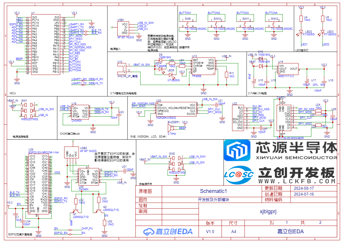
Figure 2 shows the development board and external module schematic

, and Figure 3 shows the measurement and calibration schematic. For the
software design
, my plan is to base the entire system on the firmware library provided by the CW32 official website. System resource management will be implemented using the FreeRTOS operating system (https://github.com/FreeRTOS/FreeRTOS-LTS), the interface will be implemented using uGUI (https://github.com/achimdoebler/UGUI), and the host computer will be designed using Python. The device and the host computer will connect directly via Bluetooth. The file system will be implemented using FatFs15 (http://elm-chan.org/fsw/ff/00index_e.html).
Problems Encountered During Implementation
However, the ideal is beautiful, but reality is cruel. Many intractable problems were encountered during software programming and hardware debugging. Fortunately, the most basic voltage and current measurement was still achieved.

The design problem
is shown in Figure 4. Since the ESP32S3 requires at least 500mA of current to power on, while the SE8550 can only output 250mA, an LDO was needed to support the ESP32S3. Okay, the first problem arose: an LDO capable of supplying high current could not withstand excessively high measured voltages, and an LDO capable of withstanding excessively high measured voltages could not supply high currents. Unfortunately, one cannot have both. Ultimately, I abandoned the power supply for the measured power source and used only USB power and a 3.7V lithium battery power, sharing an AMS1117-3.3V chip to provide 3.3V voltage to the entire system. The power supply method was selected via a switch.
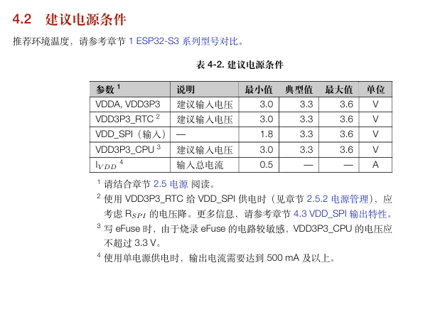
Figure 4 shows the recommended power supply conditions for the ESP32S3.
Hardware issues include
chip package selection: If I had another chance, I would say to the TL431 chip, "Seriously, is this SOT-23 even meant for human soldering?"
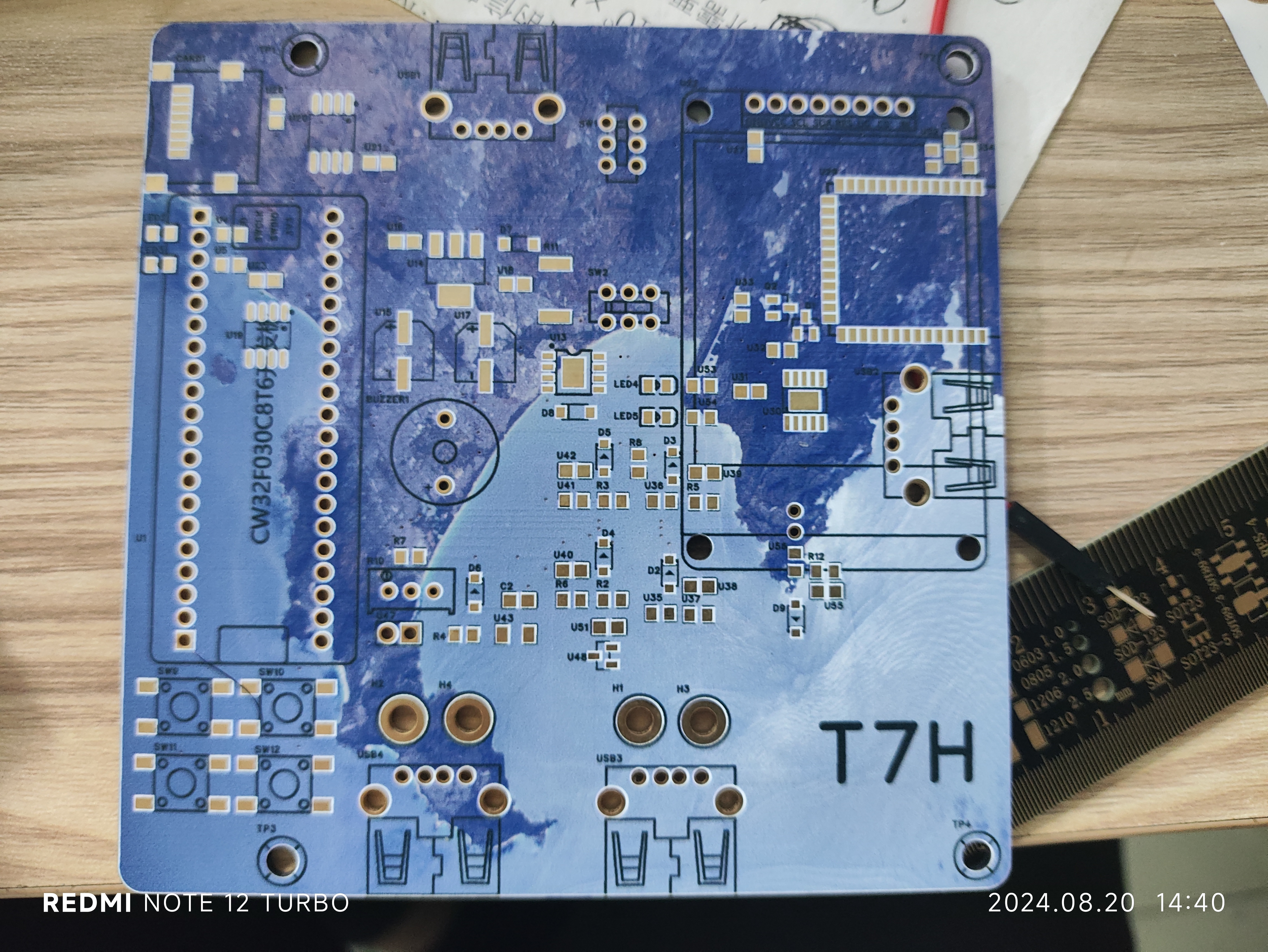
Layout issue: Let me show you my PCB traces, as shown in Figure 5: [
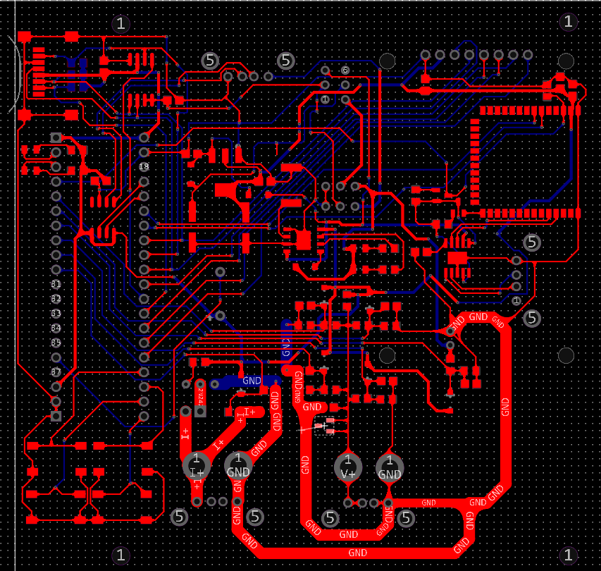
Figure 5 PCB traces]
Keen observers will have noticed that the ESP32S3 is on the right side of the PCB, while the CW32 is on the far left. They are connected via RX and TX lines. The data on these two lines travels a long distance from the CW32 to the ESP32S3, and then the ESP32S3 simply doesn't recognize the signal. Yes, it simply doesn't recognize the signal. However, if a line is run from the CW32 to the ESP32S3, the ESP32S3 can receive the data. I have no cold solder joints! No cold solder joints! No cold solder joints! An ammeter shows continuity at both ends! It's quite absurd. My current guess is that there are too many signal lines crossing in between, causing severe interference between the RX and TX signals. Okay, the Bluetooth function is also included. There are a lot of software issues.
First , there's FreeRtos. The CW32 only has 8K of RAM! 8K! I've never had such a limited memory. After porting FreeRtos, the CW32 even crashed. That's right, I allocated too much memory to FreeRtos, causing the crash. I later changed FreeRtos's `configTOTAL_HEAP_SIZE` to 5*1024 before it could boot normally, but see Figure 6 in the VCR: Figure 6: Program memory usage. This tool is called `keil5_disp_size_bar`, and the author has open-sourced it on Gitee (https://gitee.com/nikolan/keil5_disp_size_bar). Then another problem arose: the 1.8-inch screen with a resolution of 128*160 was reflected in the program, where the display thread consumed a huge amount of memory just to display the GUI correctly. As shown in Figure 7: Figure 7: FreeRtos thread usage.


Then FreeRTOS only had 76*4 bytes of memory left. Okay, the FatFs15, which I hadn't even been able to test yet, is now gone.

The final implemented functions
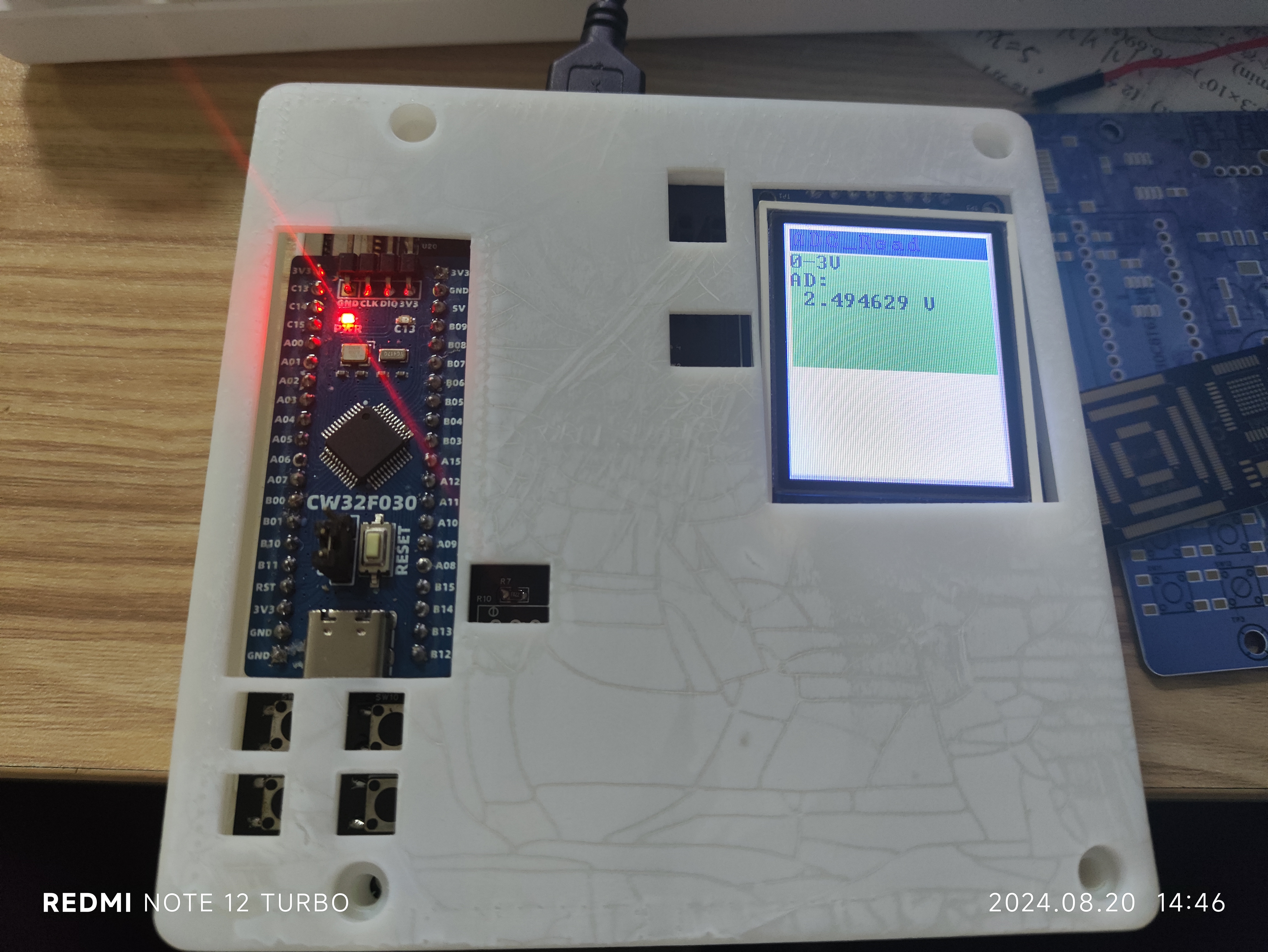
currently include 0-3V, 0-5V, 0-10V, 0-30V, and 0-3A voltage and current measurement and range switching. The measurement data can be displayed on a 1.8-inch TFT screen.
Ugly front view:

Power on: The buttons and switches are incorrectly soldered and packaged.
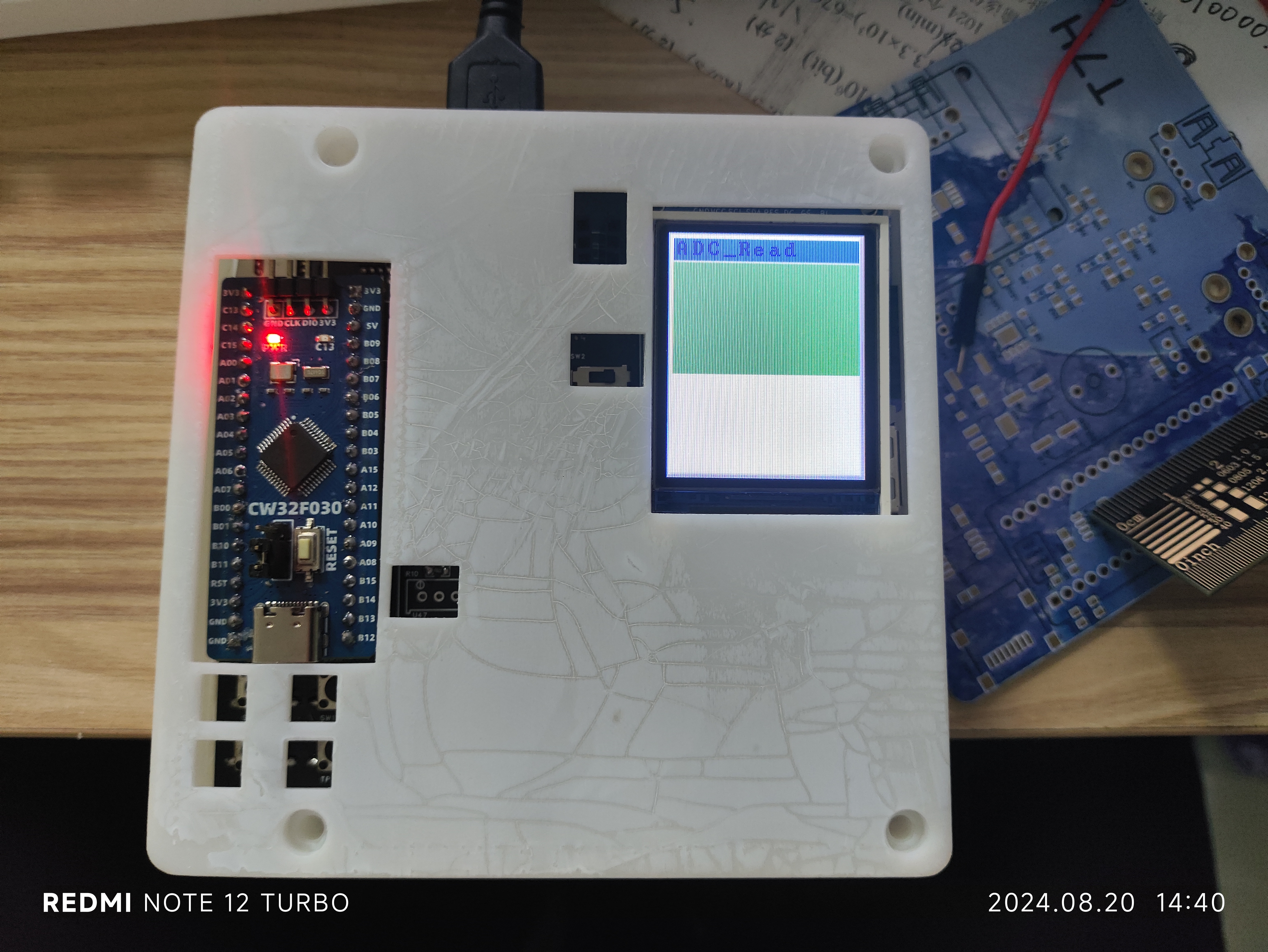
Voltage measurement:
Current measurement: It looks like voltage, but it's actually current; I just forgot to change the V to A
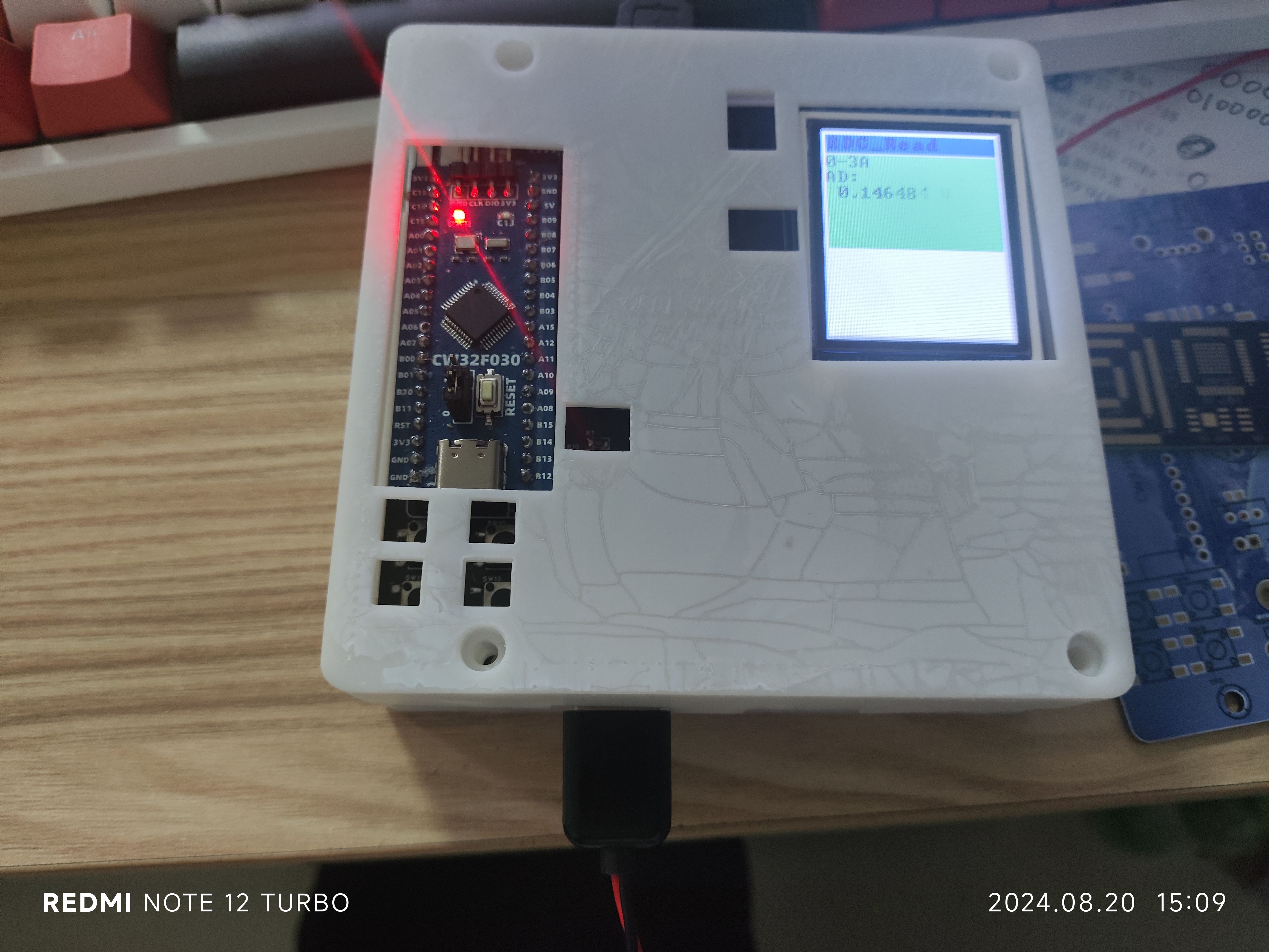
in the color silkscreen. Because this version has a bug, I have to re-make the board. I'll add the remaining functions
later
if I have the chance. I hope I can get a certificate of completion.


 京公网安备 11010802033920号

 PAL10H6CNXXXX


