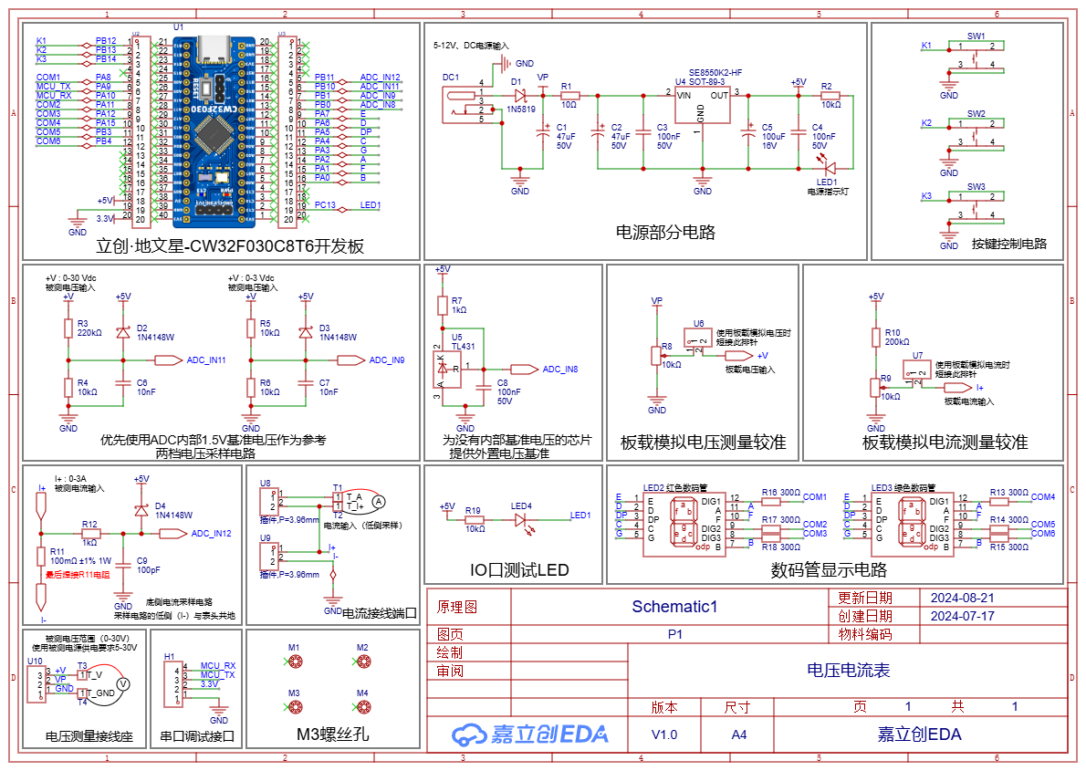
 Overall Schematic Preview;
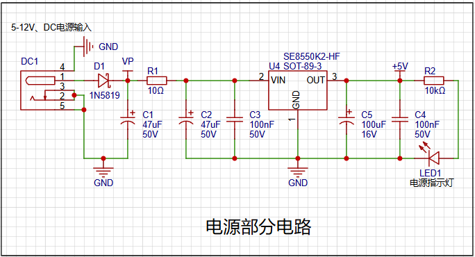 The power supply section uses an LDO (Low Dropout Linear Regulator). To accommodate a wider range of voltages, the SE8550K2 with a maximum input voltage of 40V was chosen. Because the LDO's transformation is linear, it causes less interference to other components, eliminating the possibility of power supply interference affecting our voltage and current measurements. A 1N5819 diode is connected in series at the power supply front end to protect against reverse connection issues, effectively protecting the downstream circuitry. A 10-ohm resistor is also connected in series as a fuse to prevent short circuits and damage to the board. The power supply section also uses parallel capacitors of varying sizes for filtering. The current first passes through the large capacitor for low-frequency interference filtering, and then through the small capacitor for high-frequency interference filtering, ensuring a stable and clean power supply to the LDO device. The LDO output section performs the same operation. An LED is also used to indicate the power supply status; it lights up when the power supply is functioning correctly.
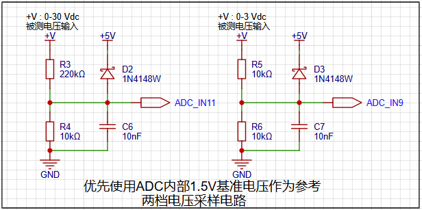
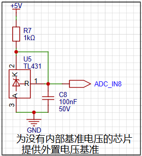 This project uses the CW32's internal reference voltage. This circuit is included to facilitate designing and using chips without internal reference voltages later. An external reference voltage is provided by a TL431 to offer a 2.5V reference voltage.
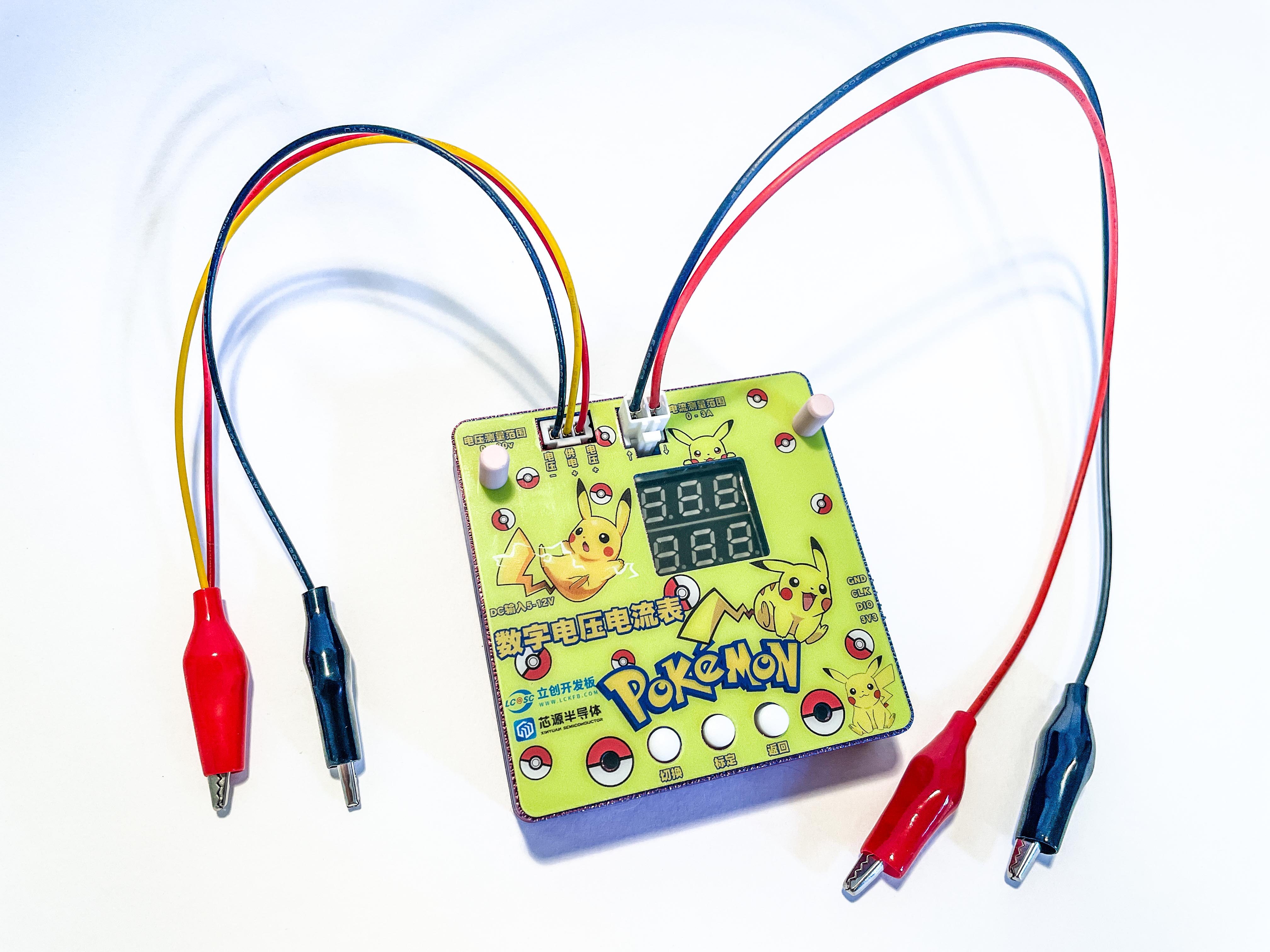
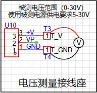 In the diagram, +V and GND are the positive and negative terminals of the voltage to be measured, respectively. At the same time, the positive terminal of the voltage to be measured can be connected to VP to power the whole system, which is more convenient and eliminates the need to prepare a separate power supply for the system. However, it should be noted that when the voltage of the power supply under test is lower than 5V, it will not be able to provide power to the system, and a separate power supply is required. In addition, for the convenience of later debugging, a 2mm banana plug for multimeter probes is used here. The multimeter probes can be directly inserted into the banana plug, which is more convenient and frees up your hands.
 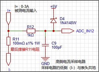 The essence of current measurement is still voltage measurement. By measuring the voltage across the measured current, the purpose of current measurement is achieved. Here, R11 is used as the sampling resistor. Because the current measurement range is limited to 0-3A, a 100mΩ resistor is chosen for sampling. Also, due to the large current, the resistor's power rating should be at least 1W. A 1kΩ resistor is placed before the measurement I/O port to limit the current and prevent damage to the I/O pins from excessive current. Together with C9, it acts as a filter for noise reduction. A 1N4148 is also placed here, serving a similar purpose to protect the ADC pins.
 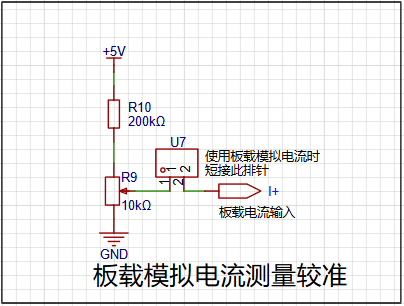 When using the onboard analog current section, remember not to solder the sampling resistor R11 beforehand, otherwise it will affect the normal measurement of the analog current. The analog current measurement is calculated by dividing the voltage across the resistor by its resistance value and then multiplying by 100, which can simulate a current of 0-2.38A for ADC measurement. (Note whether this part of the software code is set up this way.)
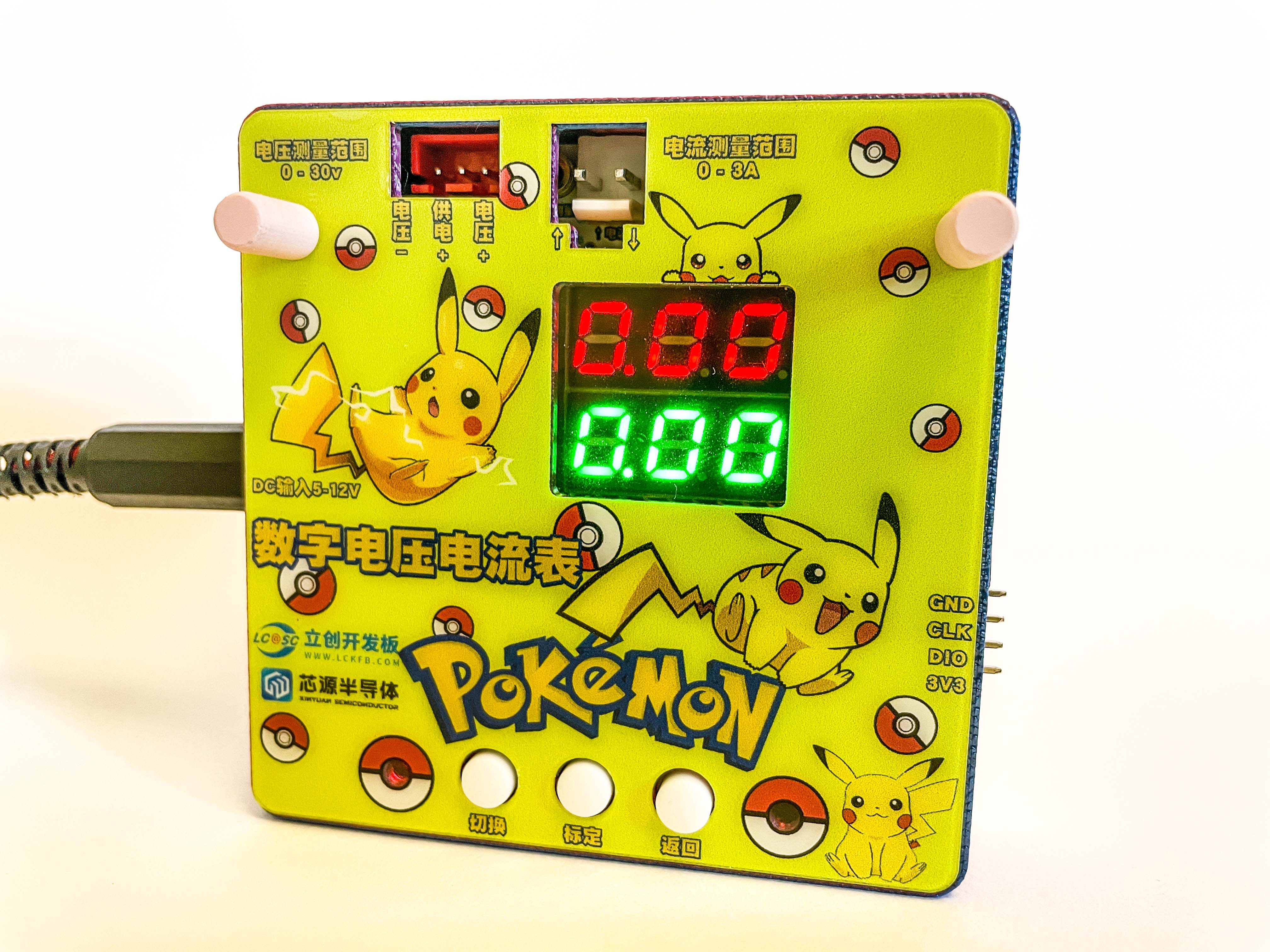
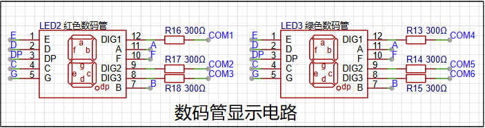 Voltage and current measurements are displayed using two 0.28-inch common cathode three-digit digital tubes. Two different colored digits can be selected for more detailed differentiation of the measured values.
 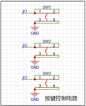 Three buttons are used to "calibrate," "confirm," and "return" the device. The specific control logic of the buttons will be explained in the finished product demonstration section.
 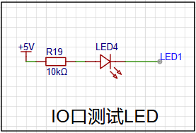 Test LEDs are used to check if the code framework is working correctly and if the test LED on the device can be lit normally.
 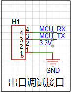 A serial port for debugging is brought out from the board for easy addition of other modules later.
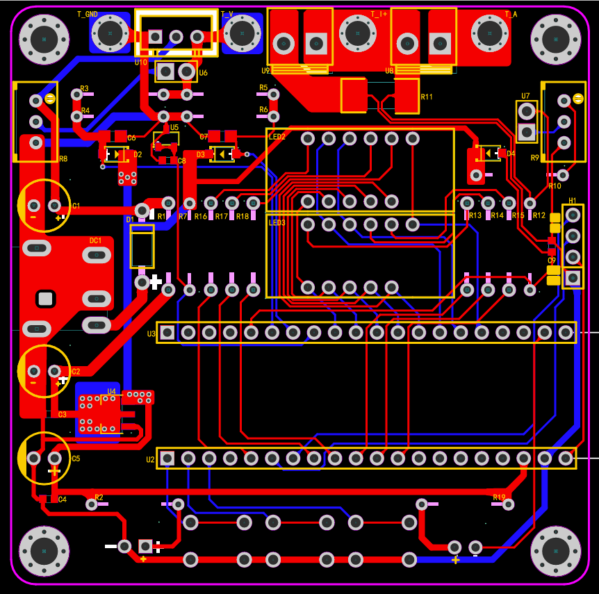
 The PCB utilizes JLCPCB's color silkscreen printing technology, with text markings on each terminal for a clearer understanding of their function. The silkscreen text also features a distinctive design, complementing the "Pikachu" motif. Since this device is a voltage and current meter, Pikachu, the electric mouse from Pokémon, was chosen as the mascot to ensure stable and reliable voltage and current measurements. PCB Body Preview
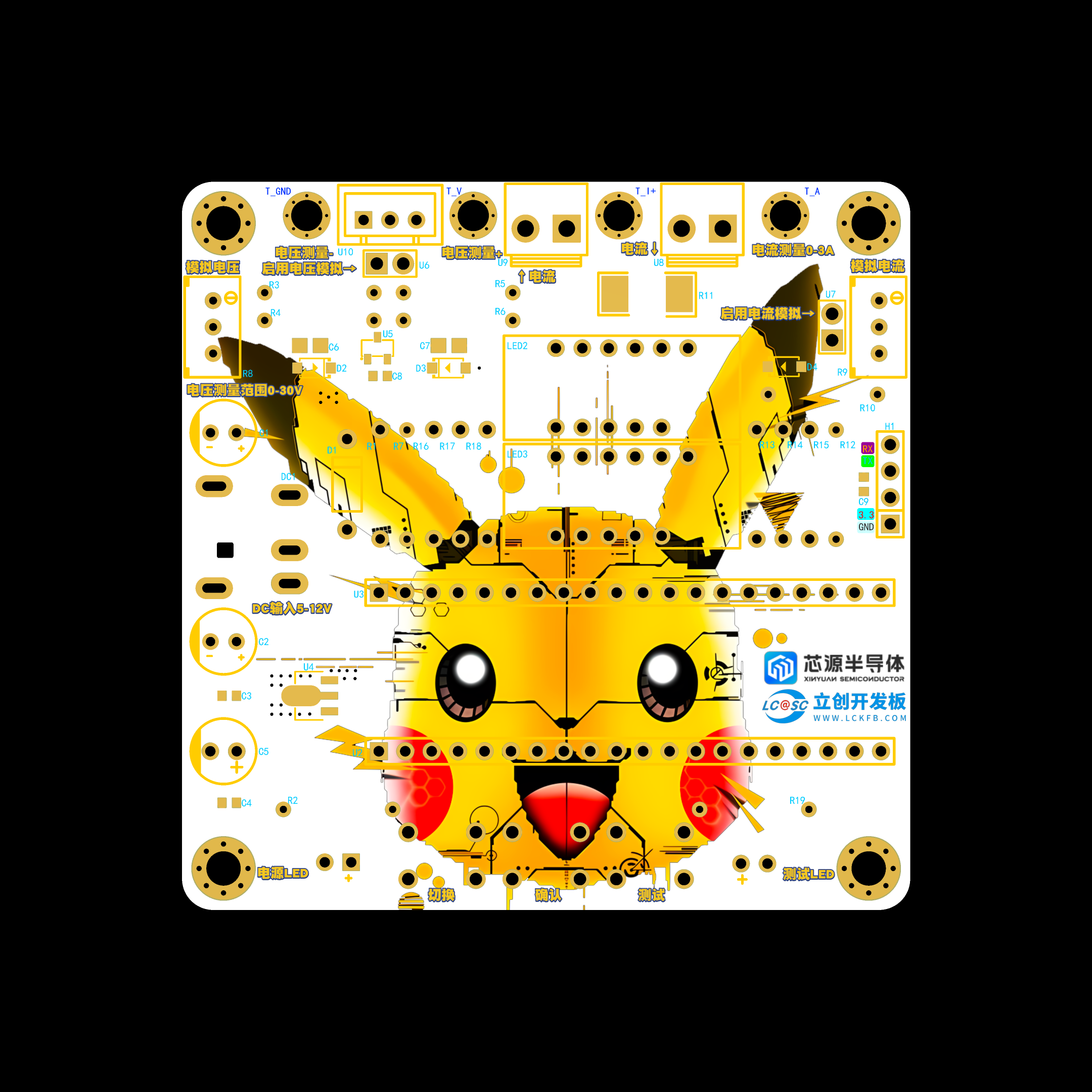
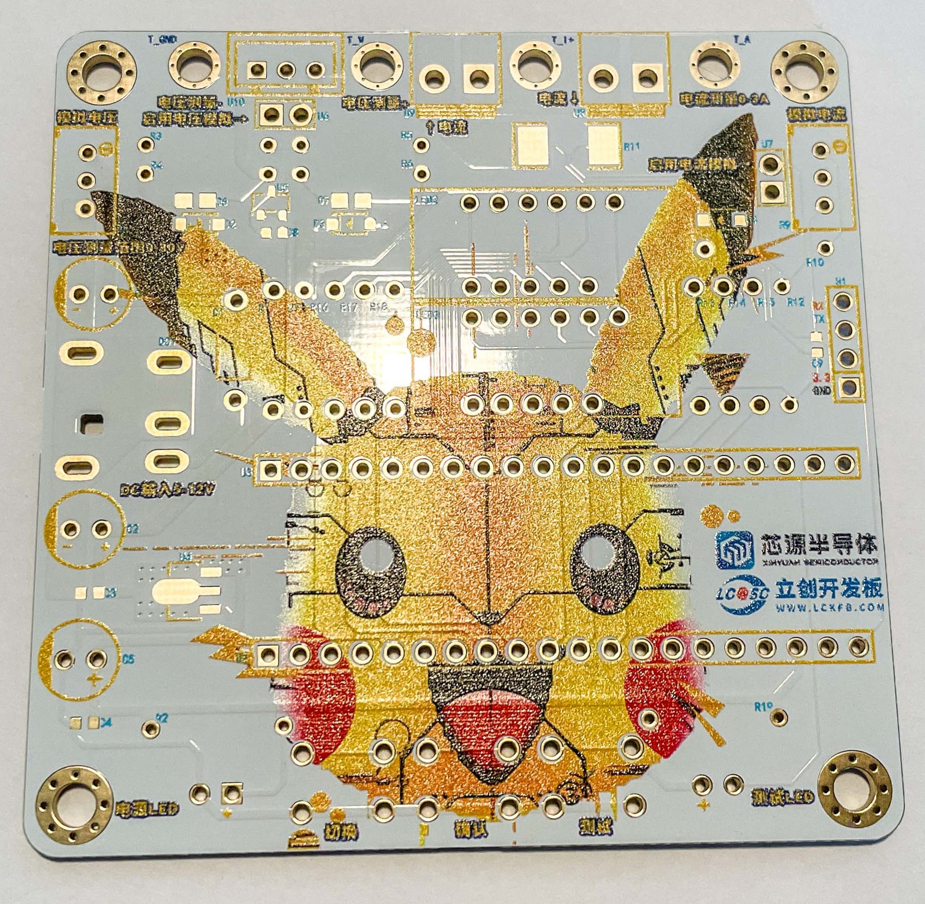
 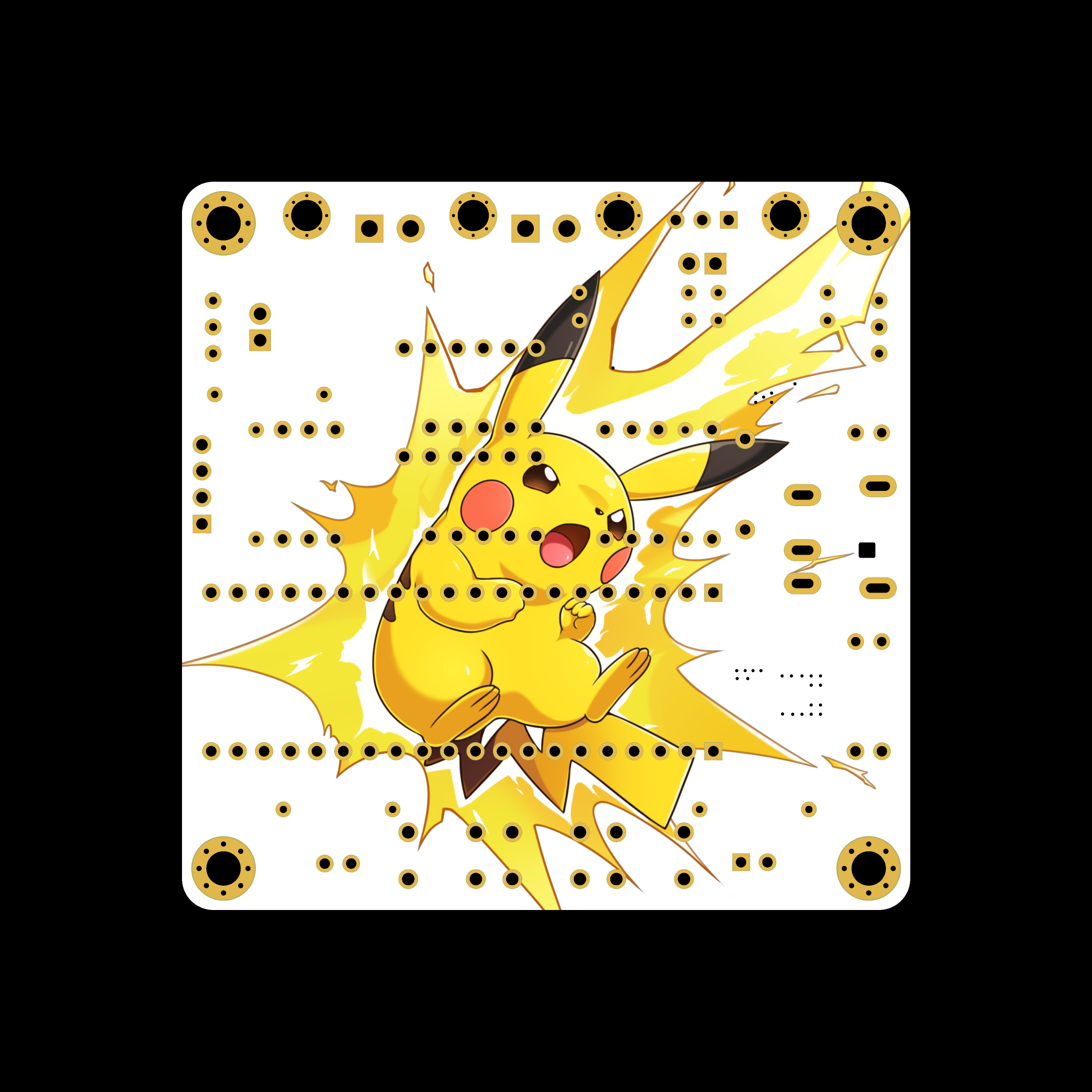 (Front): PCB 3D Preview
 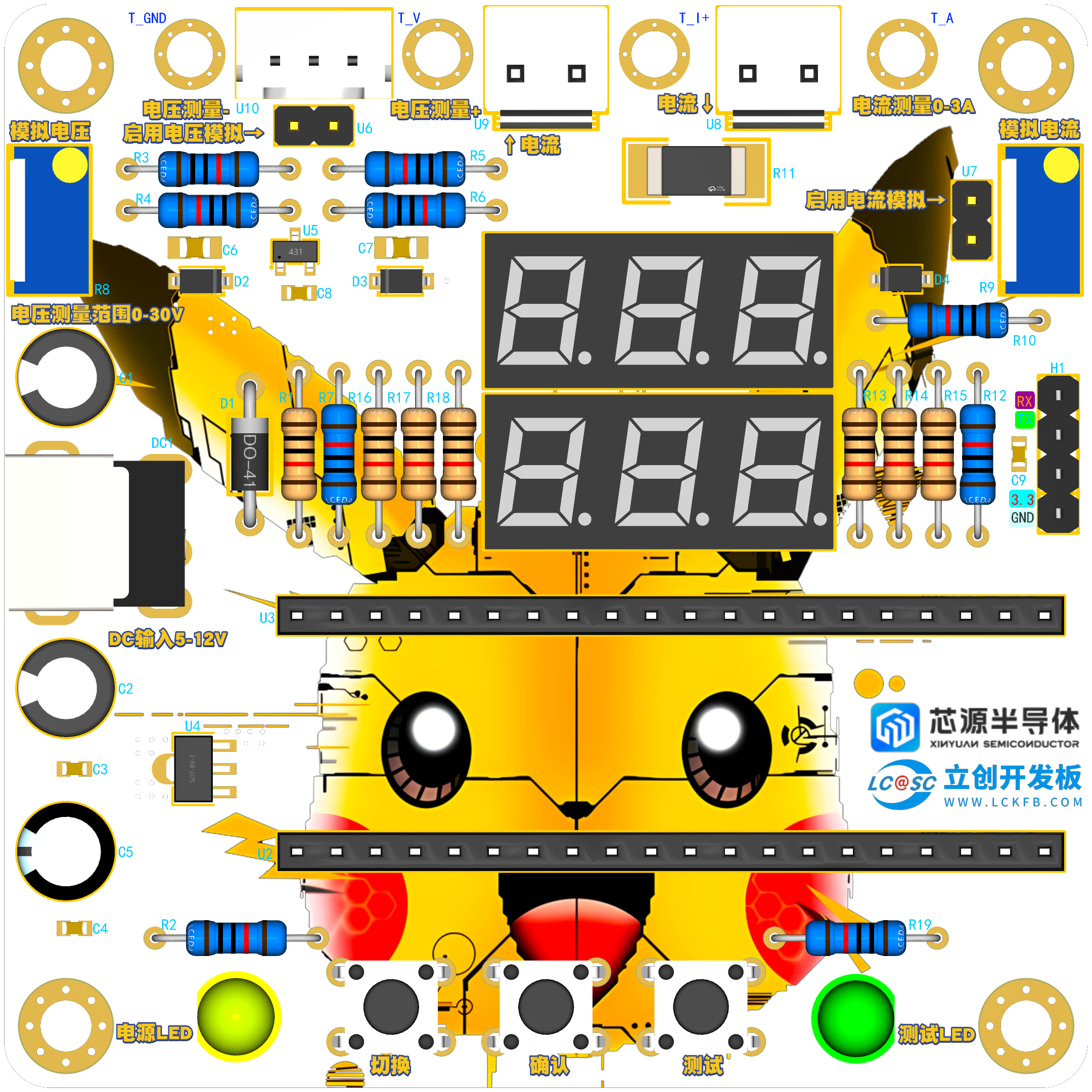 (Back):
  PCB Housing Display:
  The housing consists of two main parts, top and bottom. The top cover is connected to the housing via a thermocouple nut, which will be indicated in the product description.
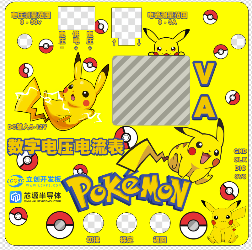
 The PCB is very attractive, with clear and vibrant color silkscreen printing. The integrated gold plating further enhances its appearance.
  Soldered PCB Display:
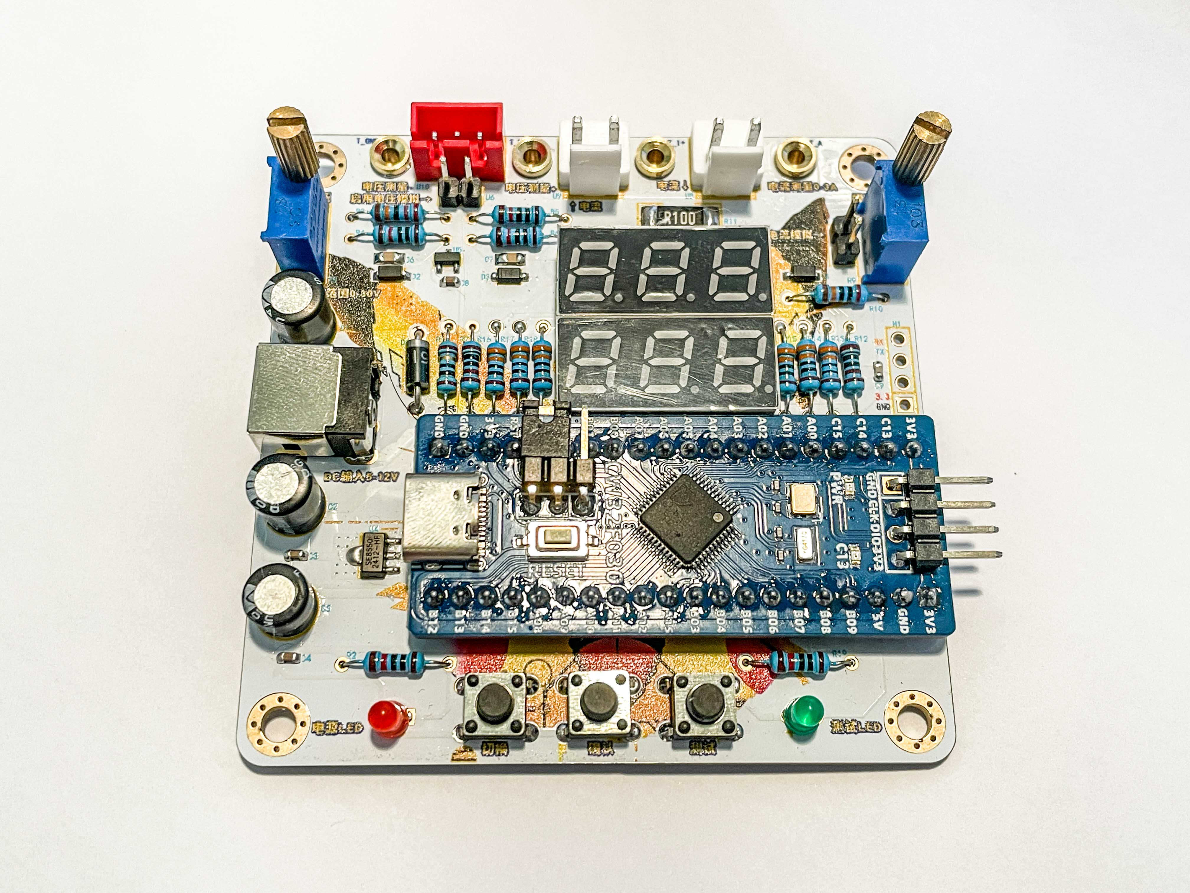 During soldering, some design issues were discovered. The initial design intended for the development board to plug into the expansion board, but this resulted in a large, less compact casing. Therefore, the development board was directly soldered to the expansion board via headers, significantly reducing the casing height. However, this also presents some drawbacks: the development board cannot be removed, making troubleshooting difficult. Also, while the height is reduced, the Type-C port on the development board is blocked by the electrolytic capacitors, preventing connection to the Type-C port. Another modification was the jumper headers on the development board. Originally straight-pronged, they were replaced with angled headers to maintain a cleaner, more aesthetically pleasing casing. This allows for jumper functionality without affecting the casing height. Later, we found several areas for optimization. For example, the wire-to-board terminals could be replaced with horizontal sockets, allowing the housing opening to be placed on the side, improving the aesthetics of the front panel. Also, potentiometers with shorter handles could be chosen, as the onboard analog voltage and current sensors are rarely used after calibration, so shorter potentiometers can be used and hidden within the housing.
 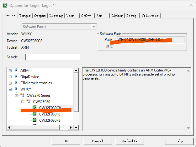 Note that if you encounter errors after compiling and downloading the code, remember to check if the chip selection is correct.
 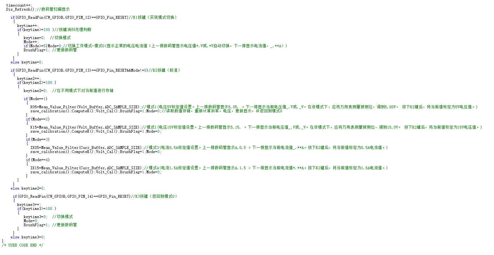 The code includes detailed comments on the button functions, facilitating modifications to the button operation logic within the code.
  The outer shell is connected by four M3 screws, and the top cover is connected to the bottom of the outer shell by four embedded M3 thermosetting nuts. The M3 screws are 8mm long, and the thermosetting nuts are 3*6*4.2mm in size.
 The button caps used here are model A101 black silicone button caps with 6*6 tactile switches, 7.5H or larger, inner diameter 3.0 feet, 7.4*4.5 (20 pieces - Taobao.com).
All reference designs on this site are sourced from major semiconductor manufacturers or collected online for learning and research. The copyright belongs to the semiconductor manufacturer or the original author. If you believe that the reference design of this site infringes upon your relevant rights and interests, please send us a rights notice. As a neutral platform service provider, we will take measures to delete the relevant content in accordance with relevant laws after receiving the relevant notice from the rights holder. Please send relevant notifications to email: bbs_service@eeworld.com.cn.
It is your responsibility to test the circuit yourself and determine its suitability for you. EEWorld will not be liable for direct, indirect, special, incidental, consequential or punitive damages arising from any cause or anything connected to any reference design used.
Supported by EEWorld Datasheet
EEWorld
subscription
account

EEWorld
service
account

Automotive
development
community

Robot
development
community

About Us Customer Service Contact Information Datasheet Sitemap LatestNews


Room 1530, 15th Floor, Building B,
No.18 Zhongguancun Street,
Haidian District,
Beijing, Postal Code: 100190
China
Telephone: 008610 8235 0740
 京公网安备 11010802033920号

 771-9993/006-203


