This voltmeter and ammeter project
is based on the "LCSC CW32F030C8T6 Development Board" digital voltmeter and ammeter, and is a student assignment from the JLCSC Training Camp.
Original example project: LCSC CW32 Digital Voltmeter and Ammeter Expansion Board.
Foreword:
After half a year, I participated in the JLCSC Training Camp again. Half a year ago, I was a complete novice in embedded development. Through the training camp, I gained initial exposure to the embedded development process and understood the general development steps. Half a year has passed, and through sporadic learning in my spare time, I feel I've become a beginner-level enthusiast. I was quite happy to see the news of this training camp opening; finally, I could write a project to practice and consolidate my learning.
This voltmeter and ammeter project seems simpler than the simple digital oscilloscope project I participated in last time, so I made some modifications to the circuit. I envisioned this meter having three functions: voltage measurement, current measurement, and resistance measurement, all using a single set of probes. I wanted it to be as small as possible so that I could hold it in my hand to see the results without turning my head to look at the meter.
Actually, I didn't change much; I mainly added some MOSFETs to control the on/off state, which should have been quite simple... my foot! I was dumbfounded after the first soldering; it was completely unusable. I checked the schematic bit by bit, and discussed it with the group members. We discovered many problems, such as reversed drain-source connections and using an NMOS as the active transistor—these were fatal errors. There were also ridiculous issues like adding a decoder and discovering that multiple MOSFETs couldn't be turned on simultaneously. "Don't add unnecessary things," Occam's words were true.
After the first failed attempt, looking at the limited time left, I had already given up hope and planned to submit it a few days late. But just as delayed justice isn't necessarily justice, what does a late submission matter? In my mind, "completing an assignment" has always been defined as "on time." So I spent two nights redrawing a version, which was indeed a bit messy (and there were a few silkscreen errors). When prototyping, I resolutely chose green. JLCPCB's speed was gratifying; I thought I would receive the board on the deadline, but I didn't expect to receive it a day and a half earlier than I anticipated, when SF Express knocked on the door. So I soldered, modified the code, and debugged in one go, finally managing to get it functioning reasonably well.
Below, I'll introduce this project.
Overall
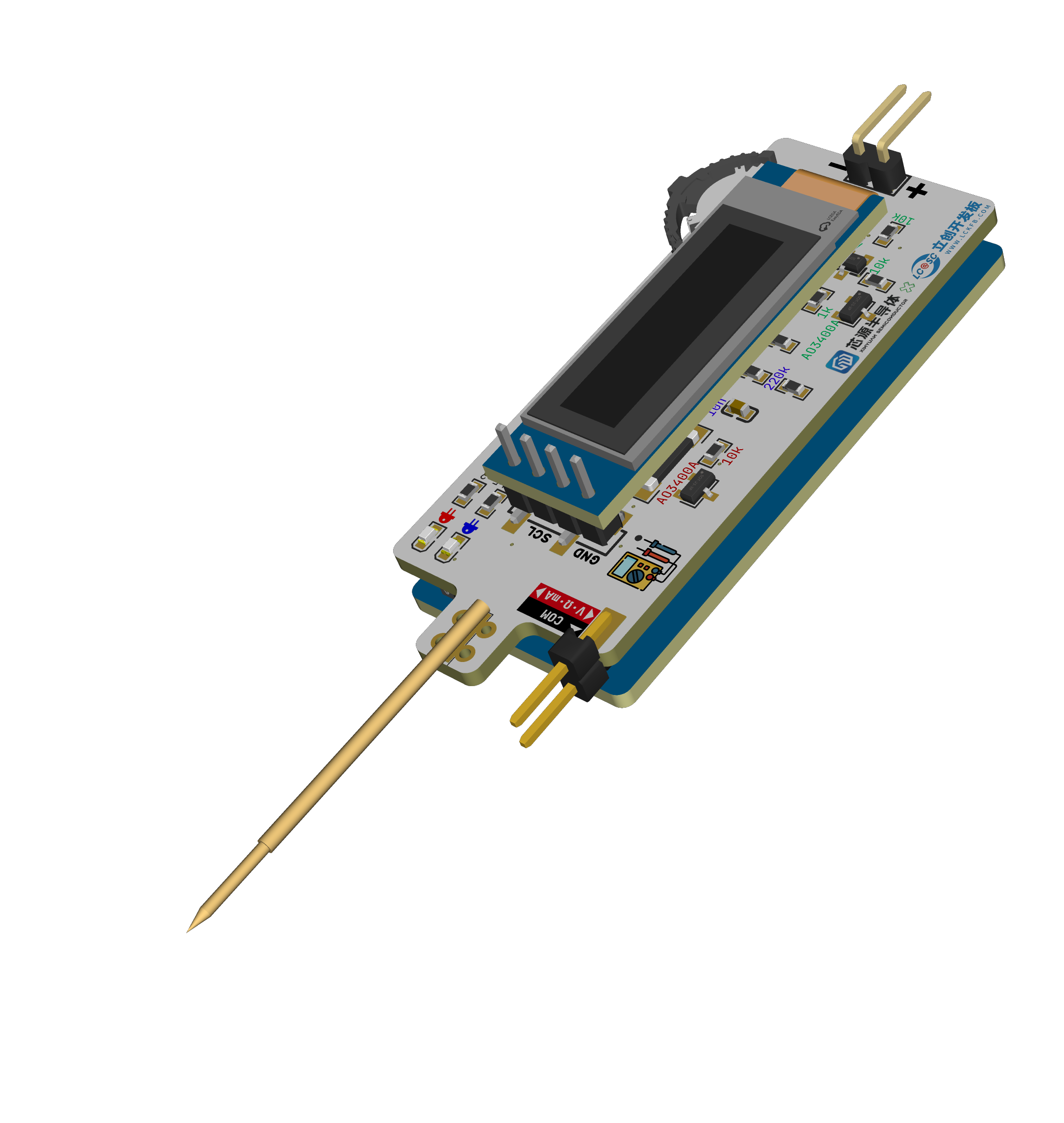
, the main features include a multimeter with DC voltage, current, and resistance measurement functions. Users can manually select each function, and the measurement range automatically switches. Within the limits of the assignment (using the LCSC CW32 development board), a sandwich structure is used to minimize its size.
A demonstration video
is attached in
the hardware section
. I will compare it with the example project in my description; due to space limitations, I won't go into detail about the original project. Please refer to the link at the beginning of this article. Regarding
the power input

, I'd like to mention that Engineer Li was incredibly detailed, covering everything from LDO selection, why an LDO was used instead of a DC-DC converter, and which capacitor should be placed first (large or small), etc. He explained many very detailed things, which was very helpful for a beginner like me.
Engineer Li mentioned that reverse connection can be prevented using a reverse-parallel diode, which I think is the case, so I made that adjustment. I didn't change the LDO; I think Mr. Li's choice was excellent. Although I didn't buy this particular LDO, I couldn't find a more suitable option for 30V VIN. Also, I initially thought that since I was making a small board, it wouldn't support such a high voltage, but considering how convenient it would be to power the meter using the board during development, 24V is still necessary. Mr. Li also mentioned that the original circuit used a 10k current-limiting resistor for the LED, which is glaring and saves power—it's incredibly thin! However, I think a 10k resistor wouldn't light up my surface-mount LED, so I used a 1.5k resistor.
Regarding

the voltage reference chip, I'm actually quite confused. I feel that the wiring should follow the schematic, and I asked GPT, and it seems that's better, but I don't know if that's true. However, this makes routing difficult, and given the time constraints, I just wanted it to be connected. I don't know if my understanding is correct; the example projects and the two projects I found online also seem to prioritize connectivity over a separate feedback circuit. I hope someone knowledgeable can provide some guidance.
I recall the original circuit for this voltage reference was for calibration, but I didn't have time to do it, and the limited board space prevented me from adding this function. However, I used it to power the resistor sampling circuit, so I kept it. Regarding the
voltage sampling ,

aside from my previous incorrect drain-source drawing, I also drew the NMOS transistor on top, which I initially thought wouldn't have an impact, but testing showed it doesn't work. It seems that if the NMOS is used as the upper transistor, the Rds resistance is close to 0 at the moment of conduction, so the voltage across switch (s) is close to the current (d). Therefore, to maintain the conduction state, Vg must be greater than Vgs(th) + Vs, preventing full conduction.
Here, I used the NMOS as the lower transistor to control the selection of the lower resistor. The software defaults to a large range, automatically switching to a small range if the voltage is below the threshold. As for
current sampling
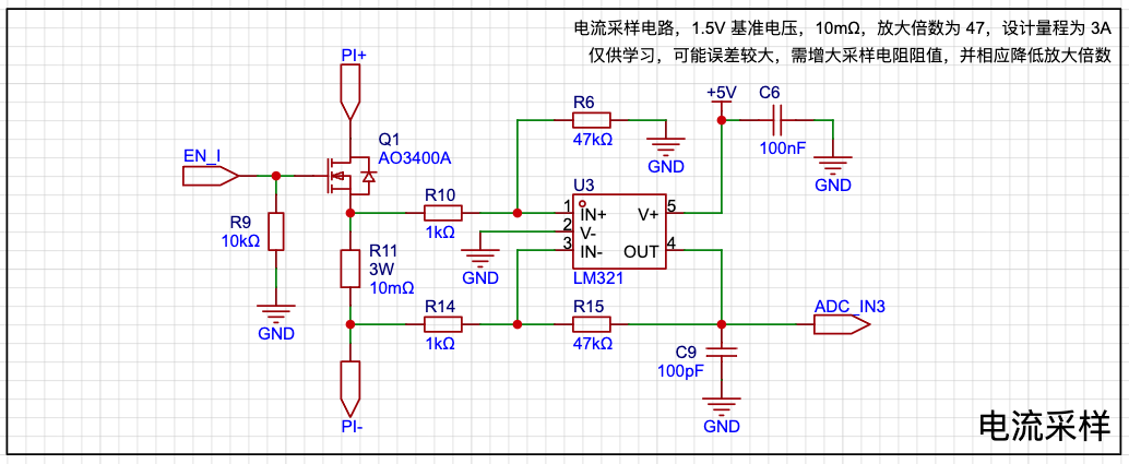
, this circuit is for learning purposes only; the actual performance is not ideal.
Here I introduced an amplifier circuit, which seems to be specifically designed to amplify the voltage across the sampling resistor. It appears to be just an inverting amplifier circuit with two additional resistors connected to the positive input, but it can be used for high-side sampling. However, I can only use low-side sampling here because all my functions share a single set of probes, and the black probe must be grounded. Additionally, using a regular op-amp results in significant errors when amplifying small voltages; it seems a dedicated current-sensing amplifier is needed in such cases. I originally wanted to add a non-amplified version, but there wasn't enough board space. During soldering, I actually used a 100mΩ amplifier with 10x amplification, which has a much lower error than a 10mΩ amplifier. For
resistor sampling
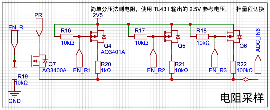
, I used a simple voltage divider method to measure resistance, aiming for a more accurate voltage. However, it seems the MCU's internal reference voltage cannot be directly used for output? Therefore, I used the 2.5V output from the previous reference voltage. This range is just an example and can be modified as needed. According to my current code, the ADC uses a 1.5V reference voltage, and can only measure up to 150kΩ, which is definitely insufficient for practical use.
Additionally, since this area is ungrounded, I was concerned that placing the NMOS in the middle might not ensure conduction, so I replaced it with a PMOS on the high side. As for
the software
code, I don't really know where to begin; I just rushed through it and there's not much to say.
I'll briefly describe my environment setup.
Because I'm using macOS, I can't use Keil, so I've always developed and learned in the PlatformIO environment (using ARM-GCC), which is how I learned with 51, GD32, STM32, and Arduino. However, since I haven't found a third-party platform package for CW32, I couldn't quickly build a development environment this way.
Later, I set up a CMake environment, called the ARM-GCC compiler, and uploaded it using PyOCD. The relevant configurations are in the code, which is a small feature of this project.
The source code is attached.
Other things
I received from this training camp—component coupons, color silkscreen coupons, panel coupons, and 3D printing coupons—have all been used. It's a pity about the color silkscreen coupon; they sent me ten boards, which was like winning a prize, but unfortunately, the design was wrong. I used both the panel coupon and the 3D printing coupon. The panel file is included in the LCSC EDA project, and the 3D shell file is attached. See the cover for a picture of the actual product.
The conclusion
is both an end and a beginning. It's not the start of the next project, but rather a continuation of efforts to improve this project. This project is far from achieving the results I wanted.
Finally, I sincerely thank JLCPCB and Sinyuan Semiconductor!


 京公网安备 11010802033920号

 K182J15C0GF5UK2V


