Design Background:
In the field of industrial automation, 4-20mA current signals, 0-10V voltage signals, and AB phase pulse signals with phase difference are widely used. In conjunction with the LCSC CW32 voltage and current meter training camp held in July-August 2024, this project utilizes the LCSC CW32F030C8T6 development board to implement these functions and accurately measure and monitor the output voltage and current.
Project Features:
The LCSC CW32F030C8T6 development board features 12 12-bit ADC input points and abundant hardware and software documentation. The official website also provides a large number of programs for porting.
1. The CW32 ADC is used to achieve accurate voltage and current detection .
2. The 0-10V/0-20mA voltage and current generator is implemented using an operational amplifier.
3. Voltage and current control can be achieved using a CW32F030C8T6 microcontroller in a numerical control manner. The microcontroller generates an adjustable PWM signal, which is converted into a voltage signal by a low-pass filter and then amplified by an LM358 to increase its load-carrying capacity.
4. The encoder is used to control the addition and subtraction of current and voltage signals, and also to generate pulse output signals.
The overall design scheme block diagram
is divided into three main modules and 12 sub-modules.

The hardware design description
includes three schematic diagrams: the main control display circuit, the charging circuit, and the voltage and current generator.

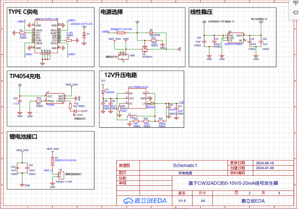
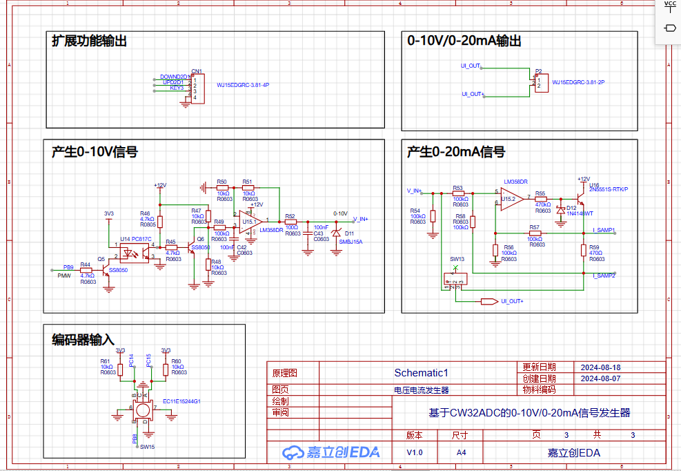
Instructions: 1. Voltage measurement sampling is performed in the 0-10V voltage measurement sampling block diagram in Schematic 1, and current sampling is performed in the 0-20mA current measurement sampling block diagram in Schematic 1. Since the output current and voltage share a common ground, current sampling can only be performed at two points, I_SMP1 and I_SMP2. Then, according to the formula: Current = Difference between two voltages / Sampling resistor, the battery voltage measurement is performed in the battery voltage block diagram. This circuit has a total of 4 analog input ADCs, which are connected to ADC_IN8, ADC_IN9, ADC_IN11, and ADC_IN12 respectively.
2. The microcontroller uses the LCSC CW32F030C8T6 development board, which uses a dual-row 40-pin IC socket. The development board can be directly plugged into it, which is very convenient. The LED digital tube display circuit uses two 0.28-inch 4-digit common cathode digital tubes. The same model is used in the design. When purchasing specific components, you can buy one red and one white for a more aesthetically pleasing appearance when lit. There are many tutorials online for the specific hardware circuit principle, which will not be elaborated here.
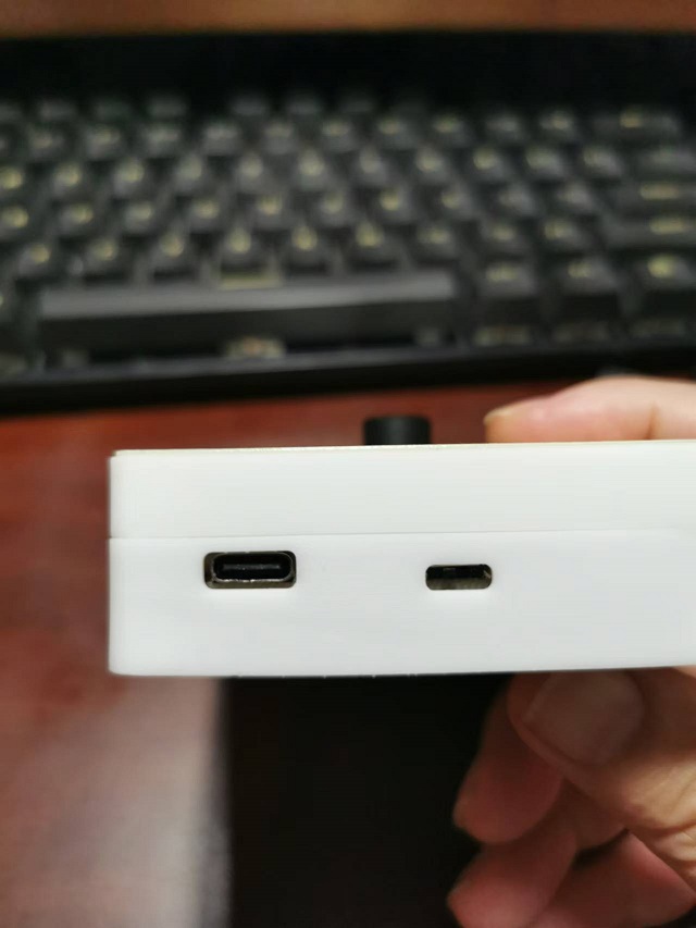
3. Power supply uses a dual-power supply of a 3.7V lithium battery and a 5V Type-C port. Charging is performed simultaneously with the 5V Type-C port power supply. A TP4054 is used for charging. An ME6231 LDO provides a stable 3.3V power supply to the CW32 development board. The 3.3V on the motherboard needs to be connected to the 3.3V on the CW32 development board. A 12V boost circuit FP6291LR provides power to the 0-10V, 0-20mA signal generator. An LM358DR dual op-amp is used. Considering the load capacity of the current source, the 12V power supply can be boosted to 24V later to match industrial applications.
4. Encoder input is used to control the microcontroller's PWM pulse width adjustment. Different PWM signals with different pulse widths are generated based on the number of rotations. R49 and C42 are first-order low-pass filters that convert the PWM signal into a voltage signal. This signal is then amplified by an operational amplifier to improve the load capacity, and finally amplified again by another operational amplifier to convert the voltage into current, generating a 0-20mA current signal.
5. Pulse Output: AB phase pulses generated during manual encoder rotation are synchronously output to the extended output port for use with industrial stepper servo motor drivers.
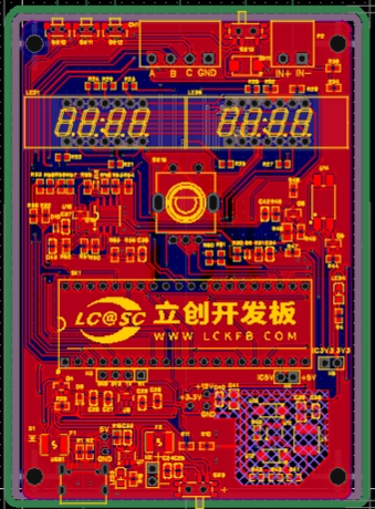
PCB Design Notes:
The PCB is generated directly from the schematic. Three function buttons are placed on the top. Voltage and current outputs use 2P ports, and the pulse output 4P port is also placed on the top. The LED digital tube is placed in the upper-middle part of the front panel. Next is the encoder, placed on the center line. The voltage generator circuit is to the right of the encoder, and the current generator circuit is to the left. The CW32 development board is placed in the lower middle section, followed by the charging port, power converter, and 3.3V circuit. The layout follows LCSC EDA's guidelines; numerous online videos explain the specific layout and routing methods.
The 3D shell is a standard top and bottom cover structure. The top button design includes three button caps and a switch handle.


During 3D shell simulation, it was found that the LED digital tube sank too low. When soldering the circuit board, the digital tube pins should not be cut off; they should be soldered higher.
Because my development board is plugged into an IC socket, the entire circuit board is quite thick. The LED digital tube needs to be taller than the development board, so even without cutting the pins, it's not tall enough. Therefore, I added mounting brackets on top to raise the height of the LED digital tube.

The panel printing was also designed according to LCSC EDA's panel design tutorial.

Software Description:
The so-called software program refers to learning how to port programs, which can save a lot of trouble. Specifically, the software uses Keil uVision5, porting and improving the voltage and current meter program from the LCSC CW32 voltage and current meter training camp. Details can be downloaded from the attached program; this is just an explanation.
ADC.C is configured with four channels for analog-to-digital conversion:
PB01_ANALOG_ENABLE(); // Enable analog pin IN9 0-10V
PB00_ANALOG_ENABLE(); // Enable analog pin IN8 Ui1 Current sampling point 1
PB10_ANALOG_ENABLE(); // Enable analog pin IN11 Battery voltage
PB11_ANALOG_ENABLE(); // Enable analog pin IN12 Ui2
Current sampling point The sampled data is stored in:
uint16_t Volt_Buffer[ADC_SAMPLE_SIZE];//Voltage sampling
uint16_t I_Samp1_Buffer[ADC_SAMPLE_SIZE];//Current sampling 1
uint16_t I_Samp2_Buffer[ADC_SAMPLE_SIZE]; // Current sampling 2
uint16_t BatVolt_Buffer[ADC_SAMPLE_SIZE]; // Battery sampling
Then, the mean filtering program is called in the main program to obtain the values of 4 analog signals.
Seg_dis.c is the digital tube display program,
ec11.C is the rotary encoder program, which configures CW_BTIM2 as the timer for the rotary encoder's timing scan.
void GTIM1_PWM_Init(void) and void PWM(void) are used in the main program main.c to generate PWM pulses.
void KEYGPIO_Init(void) and void Key_Scan(void) are used in the main program main.c to determine which button is pressed.
void Volt_Cal(void) is used in the main program main.c to convert the analog sample ADC value into the actual analog value for display.
Code block:
int main()
{
uint16_t Vi=0;
uint16_t Ri_samp=470;//Current sampling resistor
RCC_Configuration(); //System clock 64M
KEYGPIO_Init();
GPIO_WritePin(CW_GPIOC,GPIO_PIN_13,GPIO_Pin_RESET);
Seg_Init();
Btim1_Init();
ADC_init();
GTIM1_PWM_Init();
Encoder_GPIO_Init();
while(1)
{
PWM();
Key_Scan();
if (Flag_Key)
{PC13_TOG();}
//Display
if(BrushFlag==1)
{
U_val=V_Buffer;
Display(V_Buffer);
Vi=Ui1_Sampl-Ui2_Sampl;
if (Ui1_Sampl>10000 & Ui2_Sampl>10000 & Vi<200)//Display 0 when no current load is connected
{
Vi=0;
}
if (Vi>20){Vi=Vi+20;}//Error adjustment when there is a current load, 20 may be the current error of the parallel sampling resistor
if (Ui1_Sampl= 300) //Change the digital tube display value once every 300ms//
{
timecount=0;
Volt_Cal();//Voltage sampling
BrushFlag=1;
}
}
}
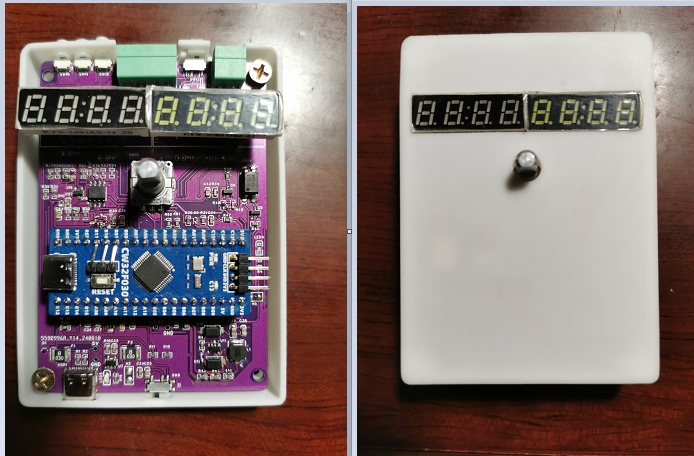
The actual production process shows
the front and back of the PCB board after production, as shown in the figure. Here, it should be noted that if the CW32 development board is placed on the 40-pin inline IC socket, it will be much higher. This causes the LED digital tube to sink, so the digital tube is also soldered with a socket. There are no components on the back, which is convenient for attaching the lithium battery with double-sided tape.

The appearance after inserting the digital tube and development board:

The appearance after attaching double-sided tape to the battery: The battery can be a 1000-1300mAh polymer lithium battery. The dimensions are smaller than the board's length and width (9cm x 7cm) and thickness (less than 6cm). This is what it looks like
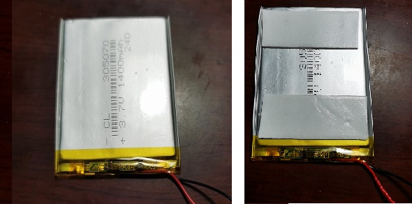
after attaching the battery to the back of the PCB:

Casing and panel:
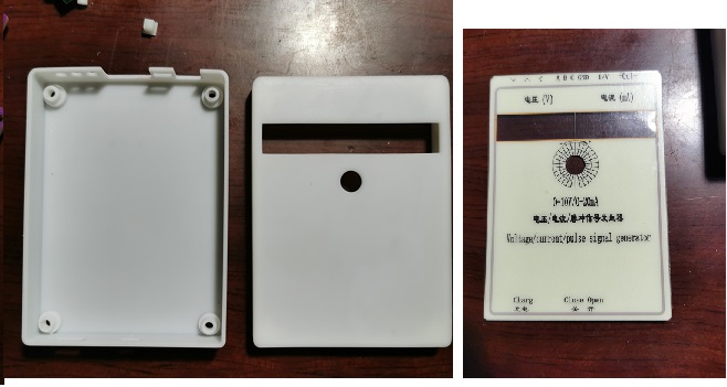
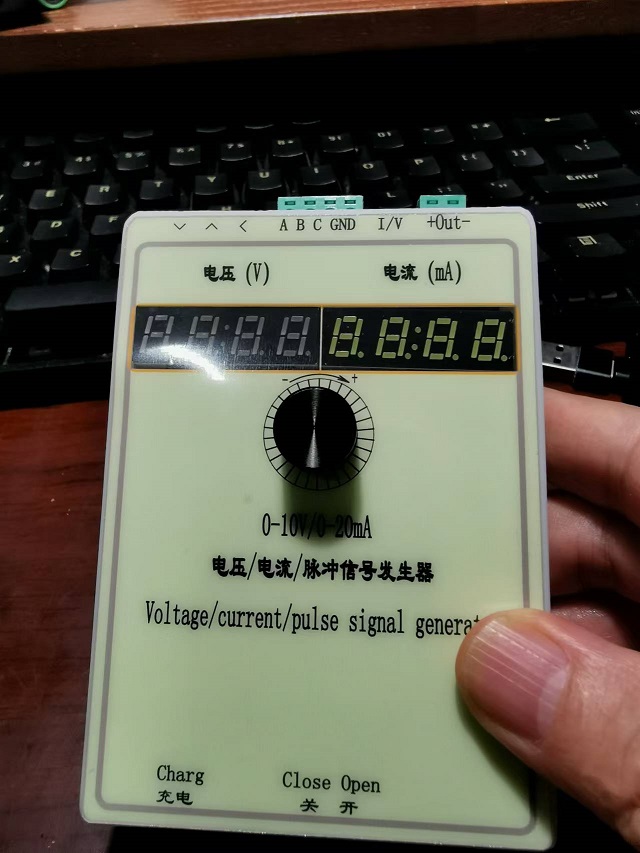
Circuit board installed: Panel attached, assembled: Actual product display. Notes: Because my development board is plugged into an IC socket, the entire circuit board is quite thick. The LED digital tube needs to be taller than the development board to display on the casing; otherwise, it will sink, as shown in the 3D preview. However, even without cutting the LED digital tube leads, it's not tall enough, so I added mounting brackets to raise the LED digital tube's height. See the attached program : EC11 Voltage and Current Simultaneous Acquisition and Display.rar. Demo video: https://b23.tv/RT94Otn


 京公网安备 11010802033920号

 M95256-DW3TG


