 . The QA pin is the data input, which is the data you want to display. The SRCLR pin is used to shift the data bit by bit, and the RCLK pin is the latch pin to latch the data. The digital tube then dynamically refreshes the displayed data.
 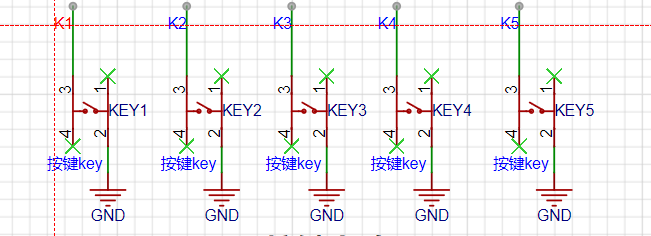 The button circuit is very simple; it can be directly connected to ordinary I/O pins. Because the CW32 has internal pull-up and pull-down resistors, I didn't draw external resistors; you can directly use the internal pull-up and pull-down resistors when configuring the buttons.
  This is the LED display circuit for my debugging purposes. Note that you need to choose appropriate current-limiting resistors; generally, the empirical value is between 1k and 4.7k.
  This is the main component of the project, the LCSC Wenxin CW32F030C8T6 development board. I designed its package and schematic library myself. It has built-in 1.5V and 2.5V voltage references, and can also use external voltage references. The ADC accuracy is 0.366mV.
 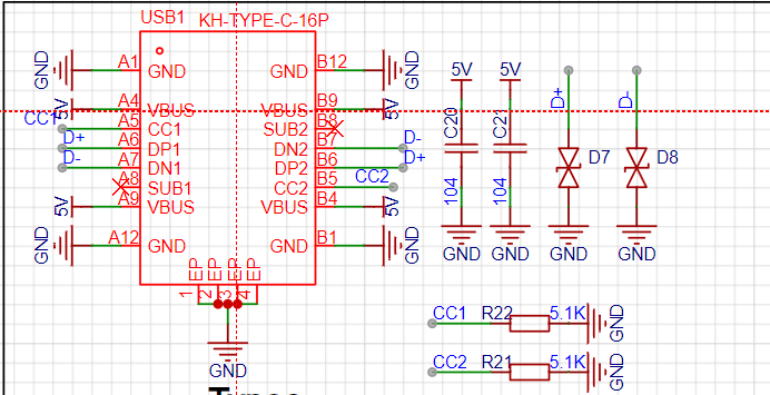 This is a USB-to-serial module for convenient debugging. Note that CC1 needs to be connected to a 5.1k resistor. The D+ and D- differential signal lines must be of equal length. The CH340 is a USB-to-serial converter.
  Set the differential pair in the rules, and then adjust
 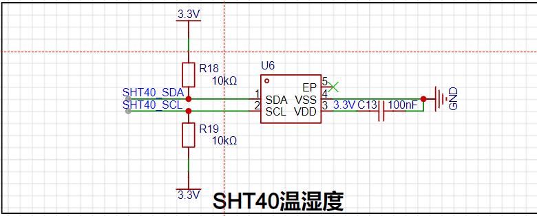 the SHT40 temperature and humidity module with equal length. Here, SDA is the data line and SCL is the clock line. The PCB traces should be differential. The R18 and R19 should be appropriately selected; general values are 4.7k and 10k. The specific values depend on the actual requirements.
 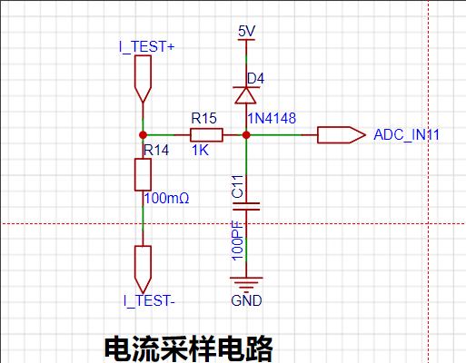 This is the current sampling module. R14 is the sampling resistor, using a 2512 package with a power rating of 3W. In the PCB design, Kelvin wiring is required, as shown in
 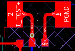 the PCB 3D image,
 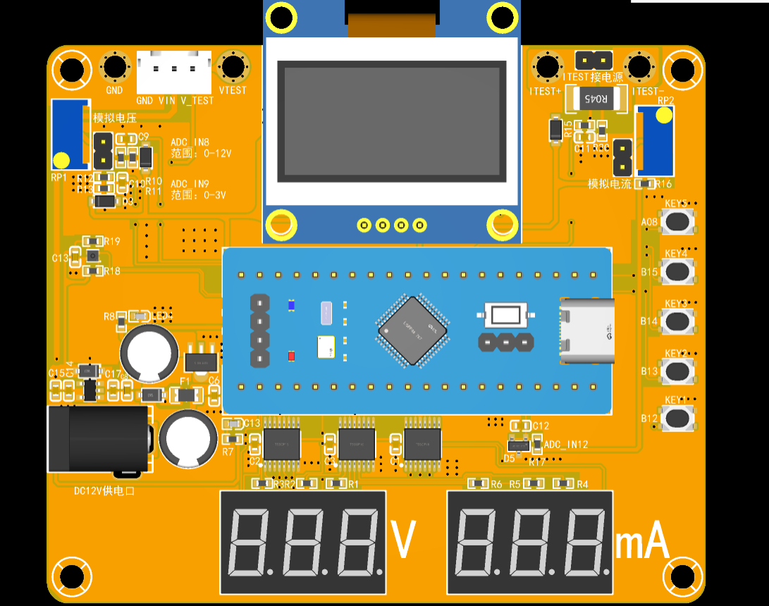 3D casing
 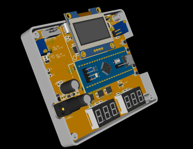 effect image, and
  software section on
 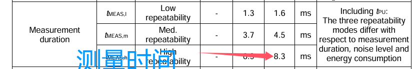 reading the protocol is very simple. Send the address and command. Here I choose repeated measurement, then read the data, and finally
  convert it according to the formula.
  . 2.2 Click Options, set the settings
 3.2 Enter the Chinese character to be extracted in the input field (only Chinese characters are allowed), and then click Generate Character Model.
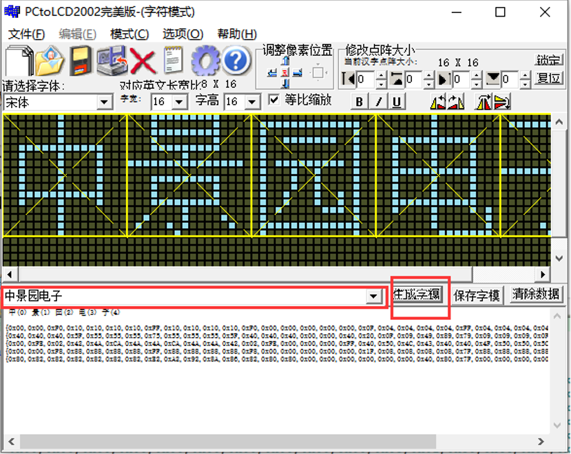
 Voltage and Current
All reference designs on this site are sourced from major semiconductor manufacturers or collected online for learning and research. The copyright belongs to the semiconductor manufacturer or the original author. If you believe that the reference design of this site infringes upon your relevant rights and interests, please send us a rights notice. As a neutral platform service provider, we will take measures to delete the relevant content in accordance with relevant laws after receiving the relevant notice from the rights holder. Please send relevant notifications to email: bbs_service@eeworld.com.cn.
It is your responsibility to test the circuit yourself and determine its suitability for you. EEWorld will not be liable for direct, indirect, special, incidental, consequential or punitive damages arising from any cause or anything connected to any reference design used.
Supported by EEWorld Datasheet
EEWorld
subscription
account

EEWorld
service
account

Automotive
development
community

Robot
development
community

About Us Customer Service Contact Information Datasheet Sitemap LatestNews


Room 1530, 15th Floor, Building B,
No.18 Zhongguancun Street,
Haidian District,
Beijing, Postal Code: 100190
China
Telephone: 008610 8235 0740
 京公网安备 11010802033920号

 5-172426-3


