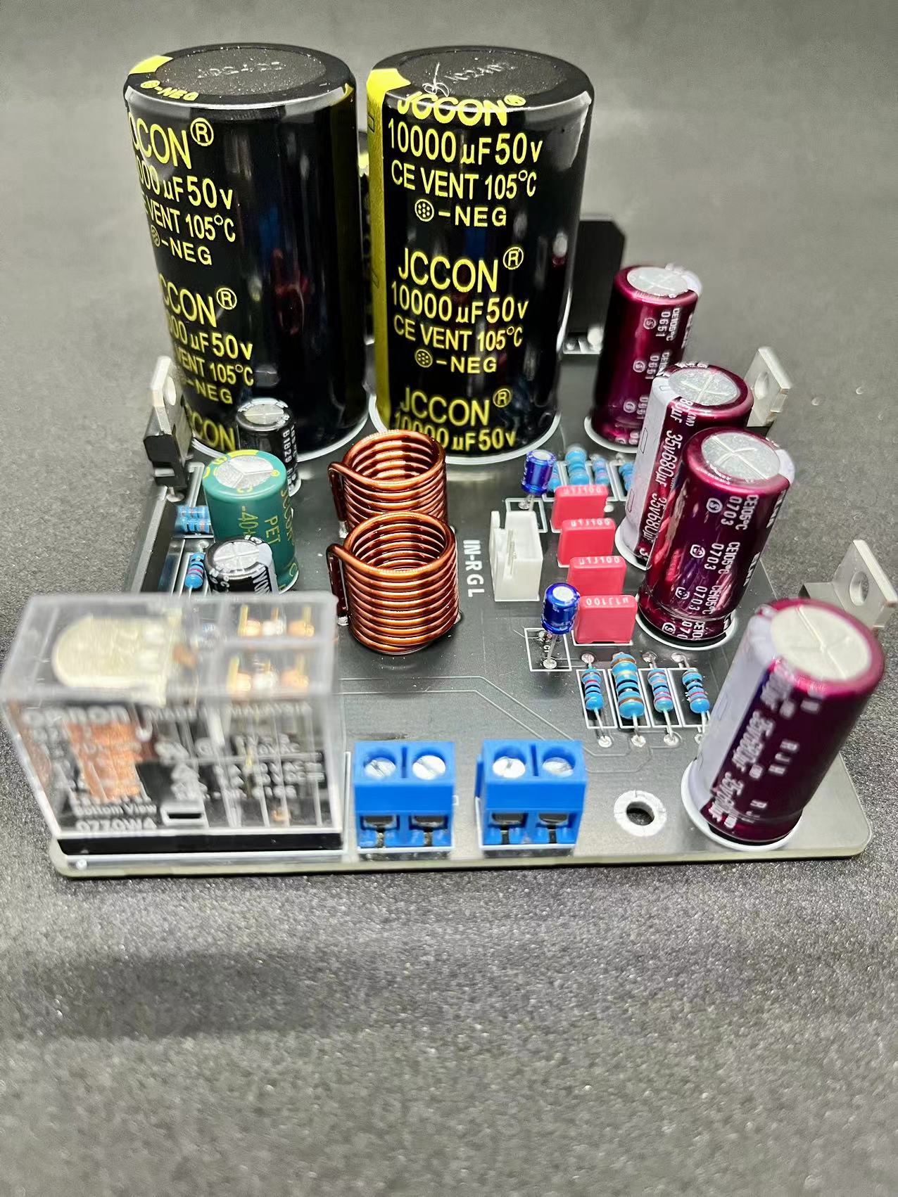
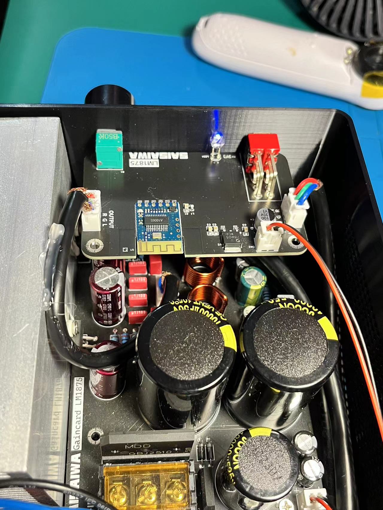
The LM1875 For GC amplifier
uses an optimized version of the GainClown architecture, offering lower distortion and a more pleasant listening experience with excellent midpoint stability.
A red oxygen-free copper hollow inductor is added to the output to eliminate unwanted noise and create a more natural sound. It features a fully protected Omron speaker protection circuit for added peace of mind.
The components are relatively expensive, costing approximately 60 RMB per unit.
According to online descriptions:
"GC" stands for GainClown, referring to the LM1875 circuit, which has undergone repeated comparisons and optimizations abroad, resulting in excellent sound quality. It boasts a wide bandwidth, fine detail, pleasant listening experience, and extremely stable midpoint.
It uses
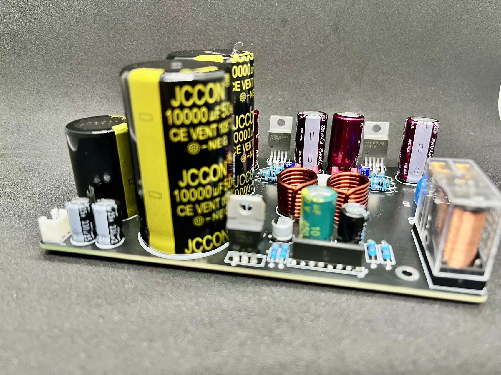
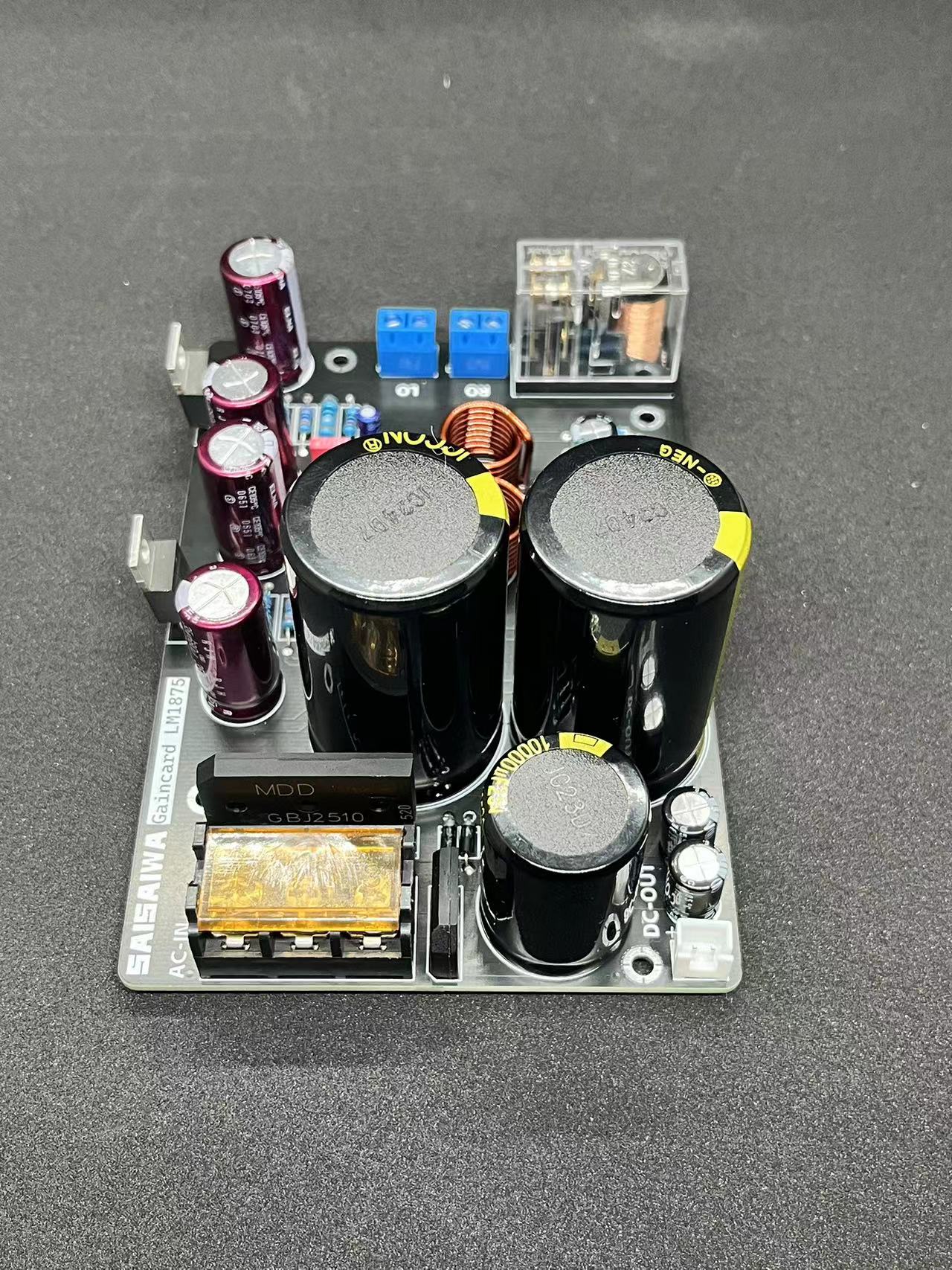
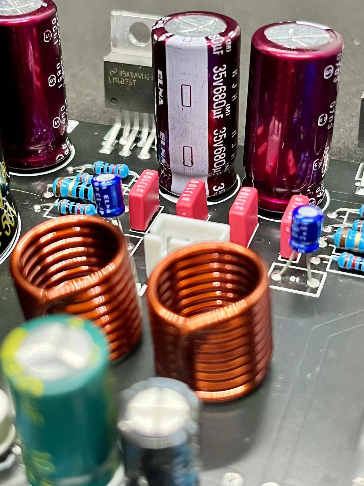
two large 10000uF JCCON black gold audio amplifier capacitors for the main power supply filter.
The high-current rectifier bridge is an original MDD GBJ2510 25A/1000V
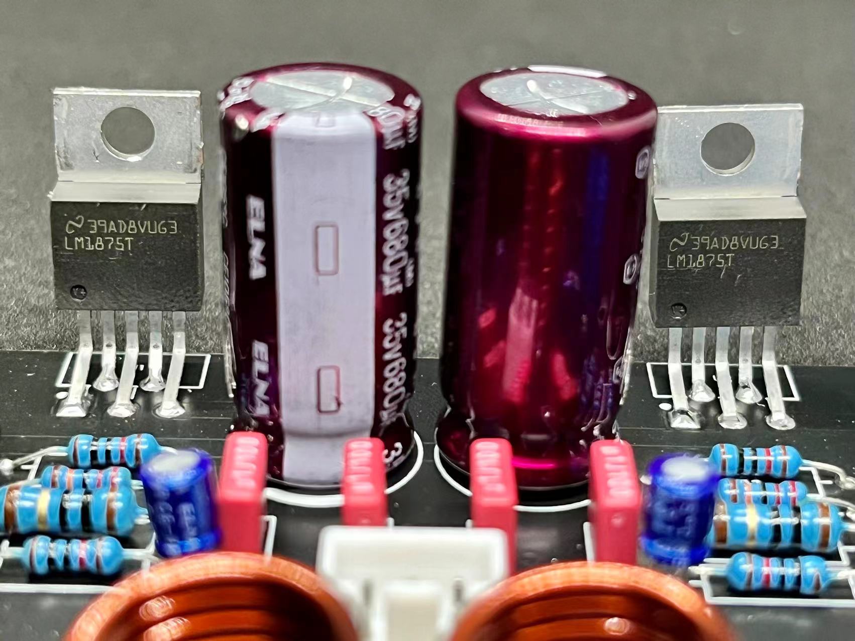
LM1875 power supply pin, and there are two small brown ELNA low-impedance audiophile capacitors (680uF) on each side.
Four decoupling capacitors are used, employing audio-grade 100nF Weima capacitors.
Two ELNA low-impedance 1uF audio coupling capacitors are used, replacing the 2.2uF Weima
/Omron relays.
This
circuit also features a separate DC-DC converter, with dual 18V power supply. One output can be converted to a 10000uF full-rectifier bridge for filtering, serving as an external preamplifier power supply
. (If used as an audio source and outputting to an 1875 power amplifier, please use a DC-DC isolation module; otherwise, it will smoke.) Recommended
operating conditions
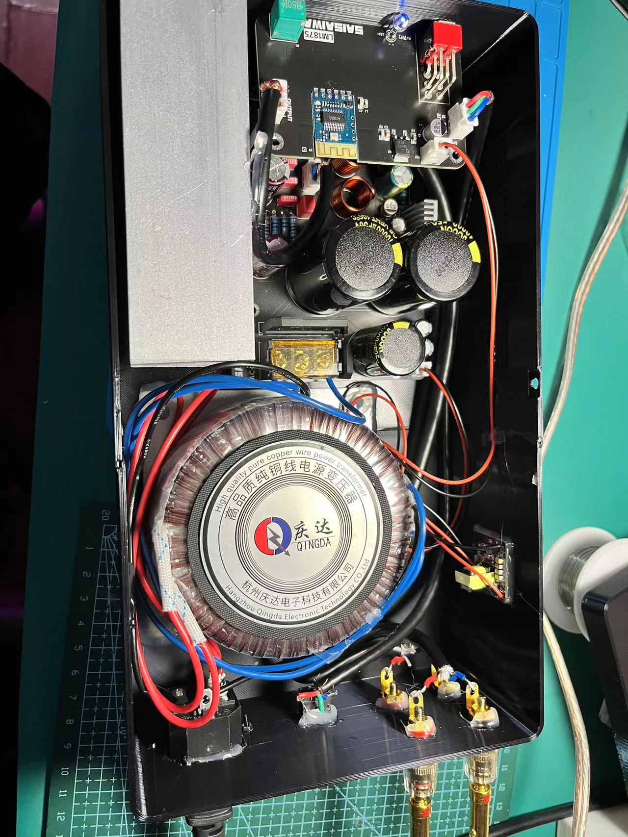
: Dual AC 18V input, preferably using a 100W dual 18V toroidal transformer.
Output power: 35W-4Ω, 25W-8Ω.
Dimensions: Length 128mm, Width 88mm, Height 50mm (excluding solder joints).
Burn-in test conclusion:
A heatsink must be installed before powering on; double-sided tape can be used for temporary application. It generates a lot of heat, with a normal operating temperature of 57°C (measured by thermal imaging).
There's a slight delay after powering on before the relay engages to turn on the speakers. For the first test, connect an audio input, such as a 3.5mm jack, and touch it to check for feedback.
There's absolutely no current noise; it's very quiet, especially for pop music, which is completely silent thanks to the relay.
Regarding sound quality,
the first comparison is between my phone (iPhone 13) at the highest quality QQ Music and the original sound on my Macbook Pro. Generally, the Macbook Pro is slightly better
, but on the Macbook Pro with Boom3D software enabled (3D surround sound and high fidelity), the difference is like night and day—you'll never go back. The bass is powerful, and the surround sound detail is excellent.
Trying to install Boom3D on a desktop (MPG Z790 EDGE TI MAX WIFI) with Windows wasn't great, but it still had some effect. The software is a one-time purchase.
Boom-channel
DC-DC isolation: https://item.taobao.com/item.htm?_u=21v3prvpe1ec&id=736429996692&spm=a1z09.2.0.0.3d0f2e8dPsajk8
LM1875T: https://item.taobao.com/item.htm?_u=21v3prvpb448&id=659592541636&spm=a1z09.2.0.0.3d0f2e8dPsajk8
Capacitor: https://item.taobao.com/item.htm?spm=a1z09.2.0.0.3d0f2e8dPsajk8&id=659083533124&_u=21v3prvp938c
https://item.taobao.com/item.htm?spm=a1z09.2.0.0.3d0f2e8dPsajk8&id=596708150488&_u=21v3prvp61f1 - (50v10000uf 30x50)
https://item.taobao.com/item.htm?spm=a1z09.2.0.0.3d0f2e8dPsajk8&id=683957666692&_u=21v3prvp4c12 - (25v10000uf 22x30)
https://item.taobao.com/item.htm?spm=a1z09.2.0.0.3d0f2e8dPsajk8&id=12910629866&_u=21v3prvpb388
https://item.taobao.com/item.htm?spm=a1z09.2.0.0.3d0f2e8dPsajk8&id=18424391074&_u=21v3prvp90ef (0.1uF 100V Oxygen-Free Hollow Copper Inductor (10pcs, White Label, Long Leg)
: https://item.taobao.com/item.htm?spm=a1z09.2.0.0.3d0f2e8dPsajk8&id=534373532779&_u=21v3prvp81af
Socket: https://item.taobao.com/item.htm?spm=a1z09.2.0.0.3d0f2e8dPsajk8&id=591602022317&_u=21v3prvp11a9
https://item.taobao.com/item.htm?spm=a1z09.2.0.0.3d0f2e8dPsajk8&id=595549566695&_u=21v3prvp7168
https://item.taobao.com/item.htm?spm=a1z09.2.0.0.3d0f2e8dPsajk8&id=718381335037&_u=21v3prvp61ae
https://item.taobao.com/item.htm?spm=a1z09.2.0.0.3d0f2e8dPsajk8&id=594713974655&_u=21v3prvp2958
https://item.taobao.com/item.htm?spm=a1z09.2.0.0.3d0f2e8dPsajk8&id=522575536295&_u=21v3prvp7a77
https://item.taobao.com/item.htm?spm=a1z09.2.0.0.3d0f2e8dPsajk8&id=522578284031&_u=21v3prvp2923
Heatsink: https://item.taobao.com/item.htm?spm=a1z0d.6639537/tb.1997196601.4.28ce7484eR4v4T&id=687484404500 (width 60, height 39120)
Prepare your own impact drill and drill bits smaller than 3mm for drilling. Use M3 self-tapping screws to secure the hole to a sufficient length.
Omron Relay: https://item.taobao.com/item.htm?spm=a1z09.2.0.0.259d2e8dTtWau0&id=692787835676&_u=21v3prvp5c8b - (G2R-2-12VDC)
It's best to buy 2/1W resistors, especially those around LM1875; larger ones are better than mine.
Toroidal Transformer: https://item.taobao.com/item.htm?spm=a1z09.2.0.0.259d2e8dTtWau0&id=671314551929&_u=21v3prvp7c02 - (100W Output Voltage: 18V Single/Dual Voltage: Dual Voltage (3 Output Wires) Input Voltage: 220V)
See pictures.


a97f301c94f822817fa6bcfee5008bec.mp4
PDF_LM1875(GC) power amplifier.zip
Altium_LM1875(GC) power amplifier.zip
PADS_LM1875(GC) power amplifier.zip
BOM_LM1875(GC) power amplifier.xlsx
91192
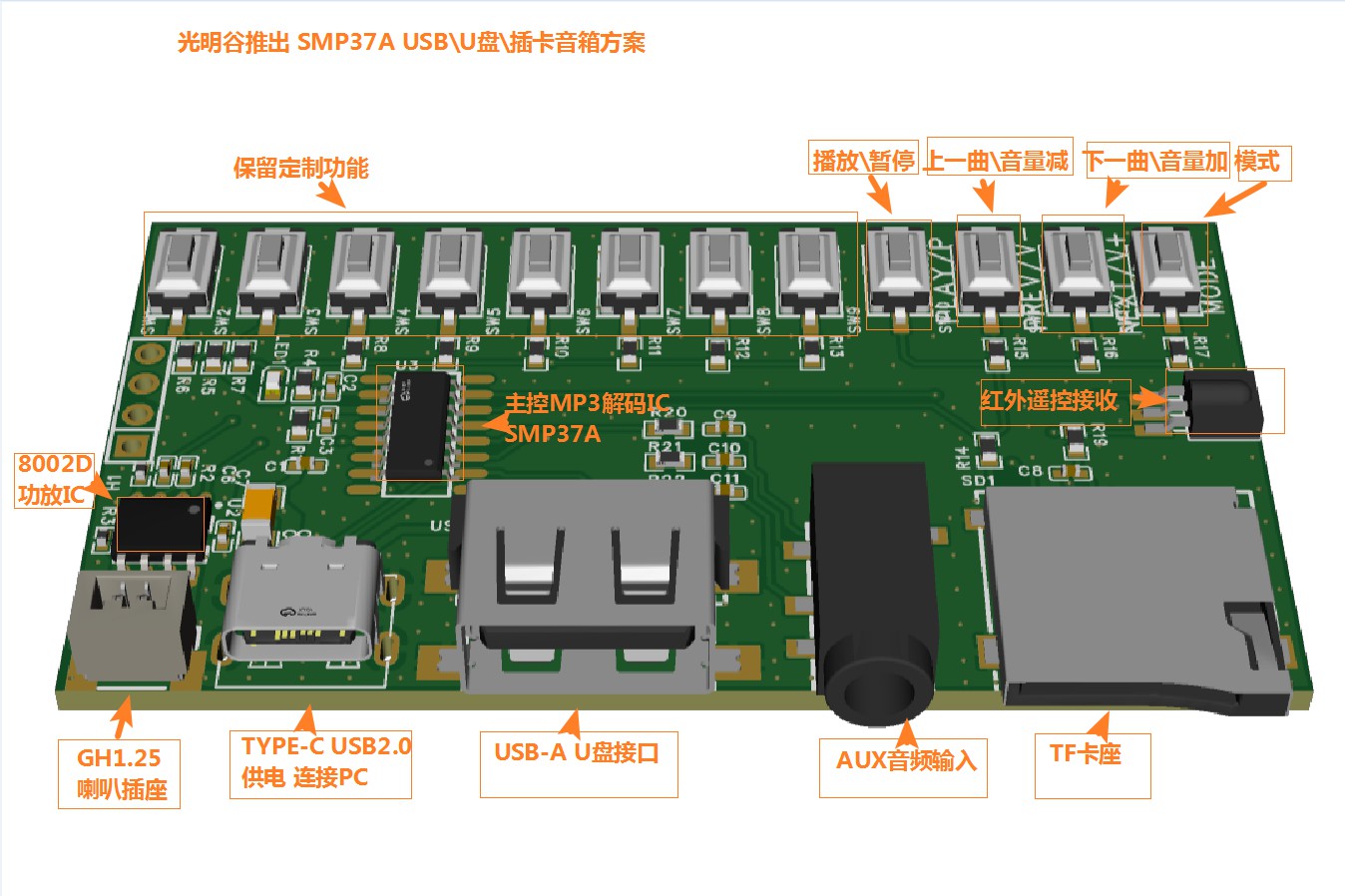
SMP37A-Player USB Speaker MP3 Player with Card Insertion and USB Flash Drive
Guangming Valley has launched the SMP37A-Player, a low-cost USB sound card solution for USB speakers, MP3 playback, and flash drives, which users can own without development.
Solution Overview:
Guangming Valley presents the SMP37A-Player, a low-cost USB speaker solution with card slot and USB flash drive playback, supporting MP3 playback. Users can achieve this without development. We have a mature solution that allows users to quickly create a Bluetooth speaker with card slot and USB flash drive playback without any code. We provide schematics, a PCB demo (open-source from LCSC, zero-development replica, worth having), and PCB layout guidance.
Solution Advantages
: Low cost, IC cost as low as 1.88 RMB .
Includes card slot and
USB flash drive music playback,
built-in sound effects,
infrared remote control support
, USB sound card, USB speaker
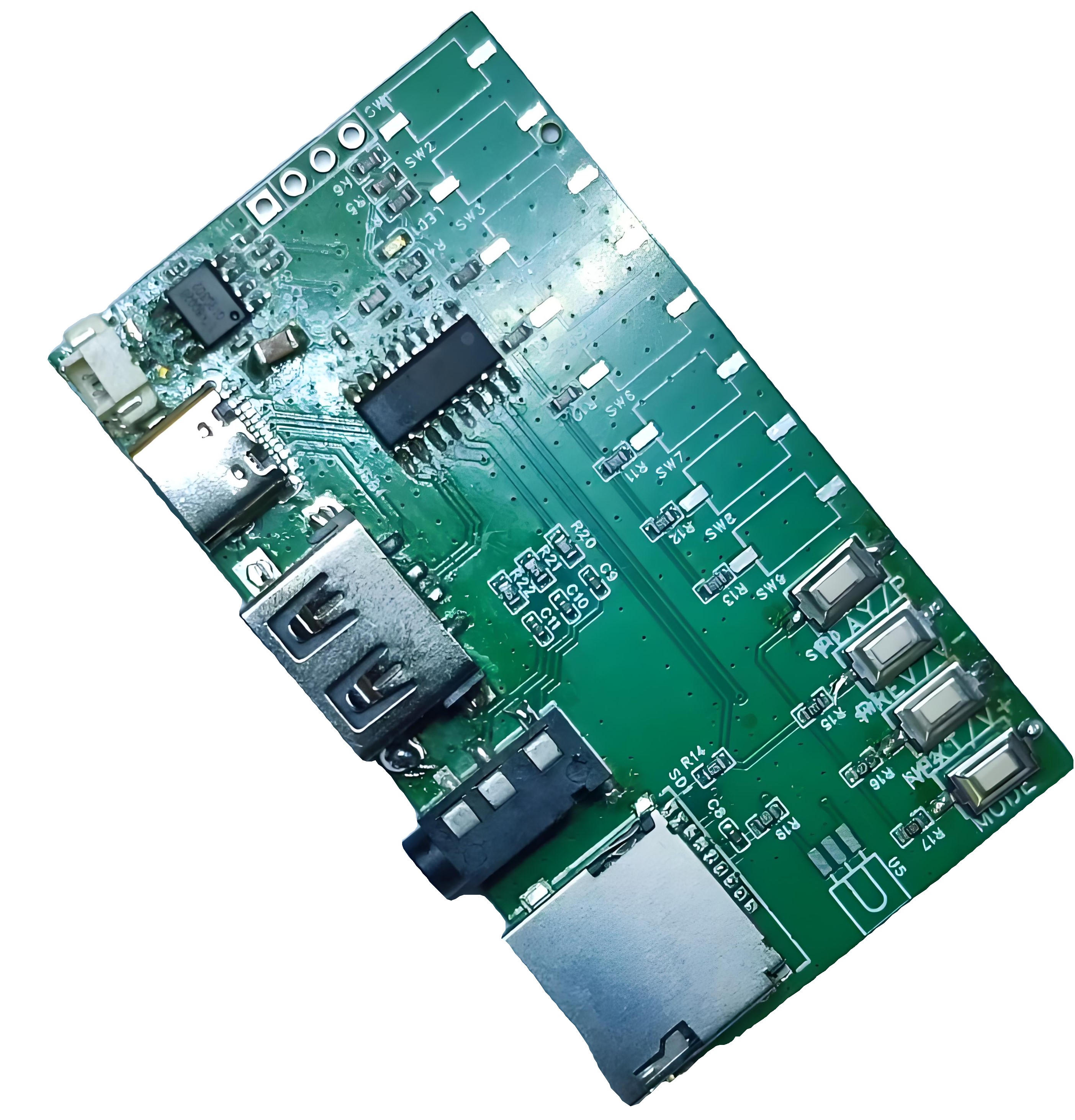
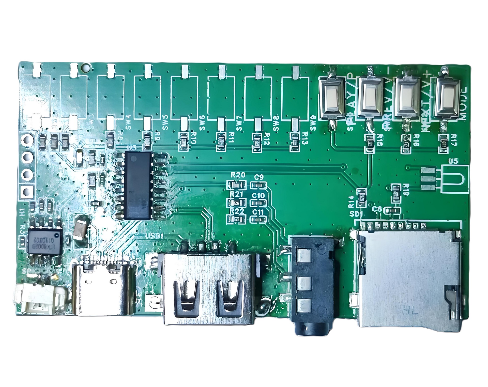
demo, board diagram,
solution block diagram, and
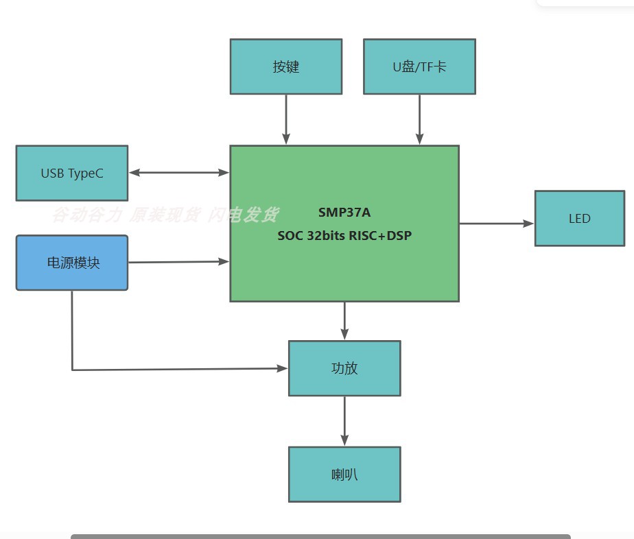
physical product images .
WeChat_20240814224334.mp4
WeChat_20240814224412.mp4
PDF_SMP37A-Player USB Speaker MP3 Player with Card Insertion and USB Flash Drive.zip
Altium_SMP37A-Player USB Speaker MP3 Player with Card Insertion and USB Flash Drive.zip
PADS_SMP37A-Player USB Speaker MP3 Player with Card Insertion and USB Flash Drive.zip
BOM_SMP37A-Player USB Speaker MP3 Player with Card Insertion and USB Flash Drive.xlsx
91193
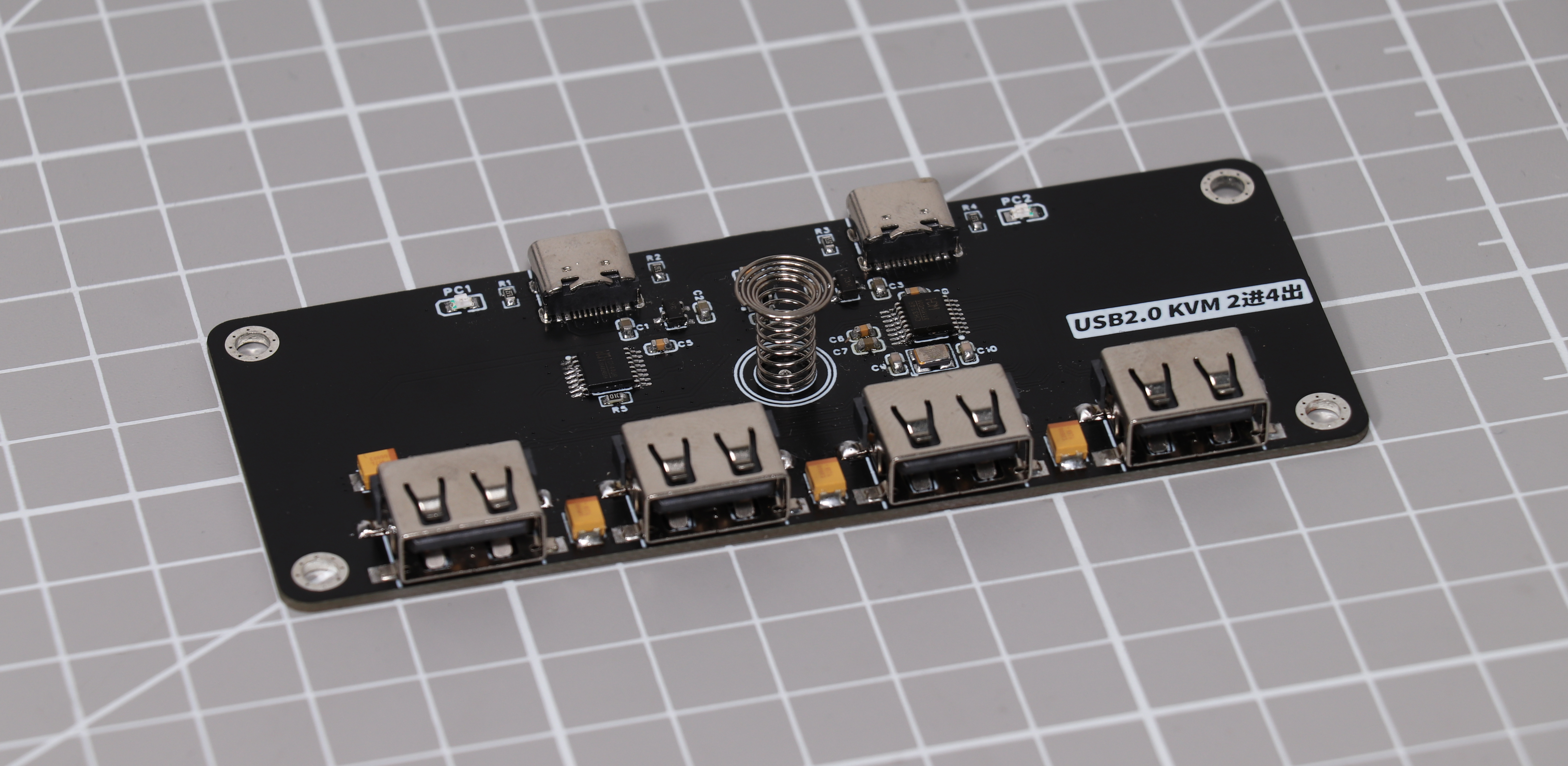
2-in-4-out USB switcher
A dual-input, quad-output USB switch with touch switching function, made using CH440R+CH334R+TTP223+CH213K chips.
I. Description:
A touch-sensitive USB switcher with dual Type-C inputs and four USB-A outputs.
It features two indicator lights to display the current input status in real time.
The power supply uses a CH213K ideal diode chip, which automatically selects the power input and provides reverse power supply.
The board thickness is 1.2mm.
The CH334R has a built-in crystal oscillator matching capacitor, eliminating the need for additional soldering; therefore, the two crystal oscillator matching capacitors on the PCB do not require soldering.
II. Function Introduction: This device
allows the use of a single set of USB devices such as keyboards, mice, flash drives, and printers between two computers, enabling one-button switching without the need to plug and unplug data cables.

III. Working Principle:
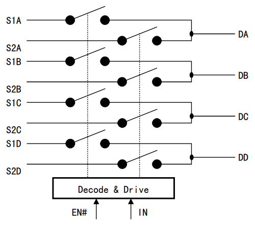
The CH440R is a QPDT analog switch chip containing four single-pole double-throw (SPDT) 2-to-1 switches.

The CH334R is a 4-port USB hub controller chip compliant with the USB 2.0 protocol, supporting high-performance MTT mode, which is superior to USB hub chips that only support STT. It features an industrial-grade design with a simplified peripheral circuitry.
The TTP223 provides one touch signal input, and its output pin connects to the IN pin of the CH440R to provide a level signal. Touch sensitivity can be adjusted by changing the capacitor value to prevent accidental touches.
The CH213K ideal diode chip has a voltage drop significantly lower than commonly used Schottky diodes and provides some over-temperature, over-current/current limiting, and short-circuit protection.
IV. Housing Design:
The housing has been verified.
Hole tolerances have been verified.
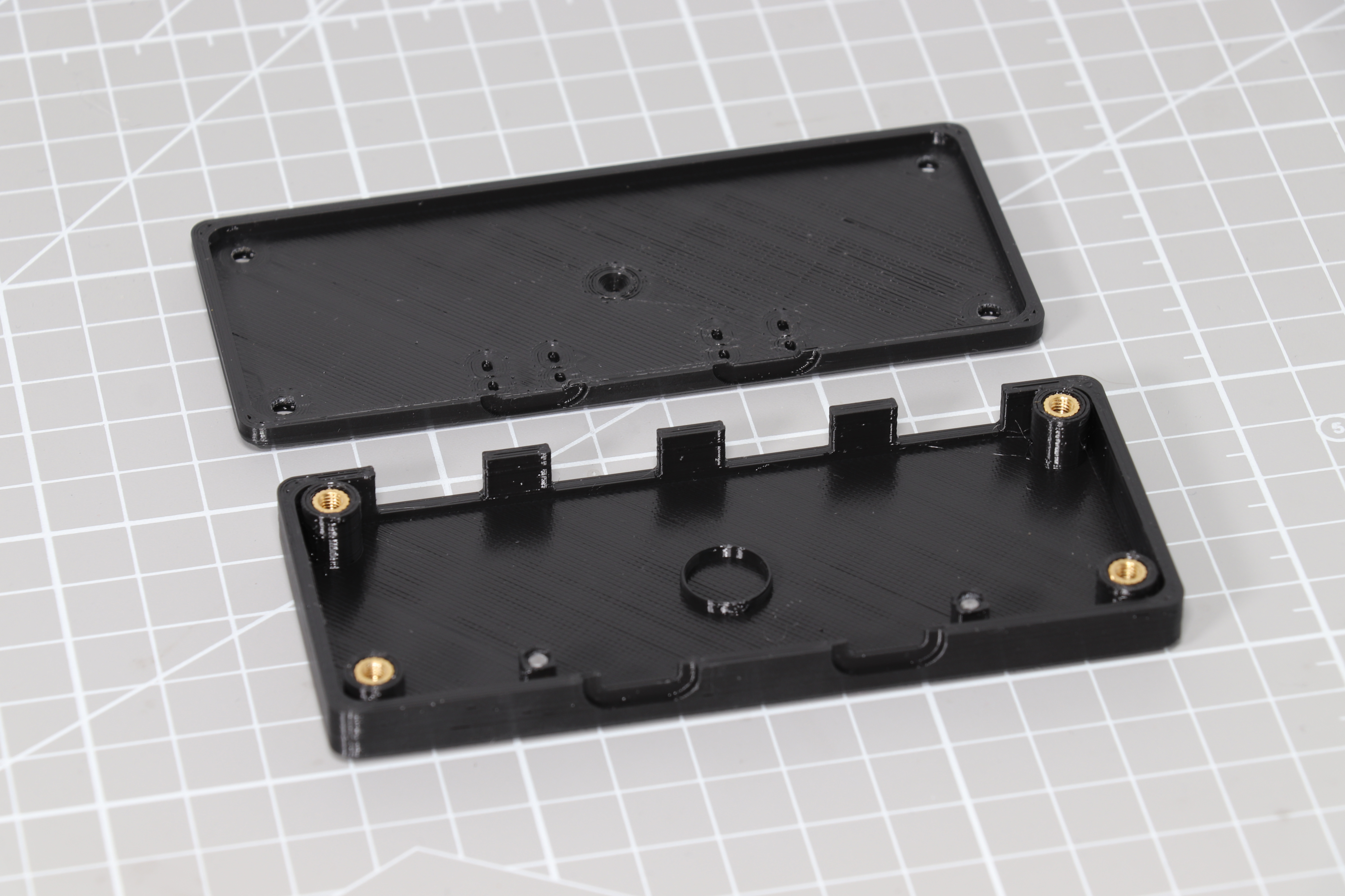
It adopts a top and bottom cover design with pre-drilled holes for M3 T-shaped thermoforming nuts for easy assembly and disassembly.
The top cover has pre-drilled holes for 2mm acrylic light guide pillars; the light guide pillars cost as low as 1 RMB/meter, achieving good light guiding effects at low cost.
3D printed using PLA material, no support required.

The bottom can be custom-engraved. Modify the bottom using the STEP file (attached).
V. Reference Project:
https://oshwhub.com/alphacc/alpha-ch440_zj-c00
Thanks to the above contributors for their open-source contributions
. VI. Conclusion:
There are still areas for optimization and improvement in the project. The wiring and layout have room for improvement. The USB differential cables only have simple length equalization and lack ESD protection components. These are areas for optimization, but my time is limited.
The four 100uf tantalum capacitors are relatively expensive; a package compatible with 10uf capacitors could be added, and soldering could be done according to requirements. Soldering four tantalum capacitors can barely power an external hard drive, but overall, it's not recommended to power an external hard drive (to prevent damage due to insufficient power). For daily use, soldering one or two 100uf capacitors is sufficient.
As of March 28th, I have been using it stably for nearly three months, occasionally encountering recognition issues, which are resolved by unplugging and replugging (possibly related to the quality of my data cable?). If you have any other questions, please provide feedback after you recreate the project.
Note: Based on my experience over the past six months, I've occasionally encountered situations where some USB devices might fail to connect during switching, even without power. Perfectionists should exercise caution when replicating this solution or consider alternative options. I will also update the 4-in-4-out CH9374B solution later (power off during switching and supports hotkeys and other switching methods), which is more perfect than the current version. A CH645W solution is also planned, but information is currently limited; I will continue to follow up.
I hope to see your submissions in the comments section! Thank you!
A 4-in-4-out switcher for CH3974B should be updated later. Those who need 4-in-4-out switches can look forward to it.
Update Log:
2024/03/28 Uploaded project and model files.
2024/03/29 Uploaded BOM to attachment; please refer to the dimensions in the table to purchase springs, screws, and other accessories.
2024/04/25 Inquired with wch technical support; the CH334R already has a built-in crystal matching capacitor, so no additional soldering is needed. Therefore, the two crystal matching capacitors on the PCB do not need to be soldered. Crystal oscillator parameters are selectable: 12M, 12-20pF, 20ppm. Does the CH334R crystal oscillator require a matching capacitor? - Qinheng Microelectronics Community (wch.cn)
updated text description on 2024/8/13.
Chip Manual.zip
USB switcher shell files.zip
USB Switch BOM.xlsx
PDF_Dual-input Quad-output USB Switcher.zip
Altium 2-in-4-out USB Switcher.zip
PADS_2-in-4-out USB Switcher.zip
BOM_2-in-4-out USB Switcher.xlsx
91194
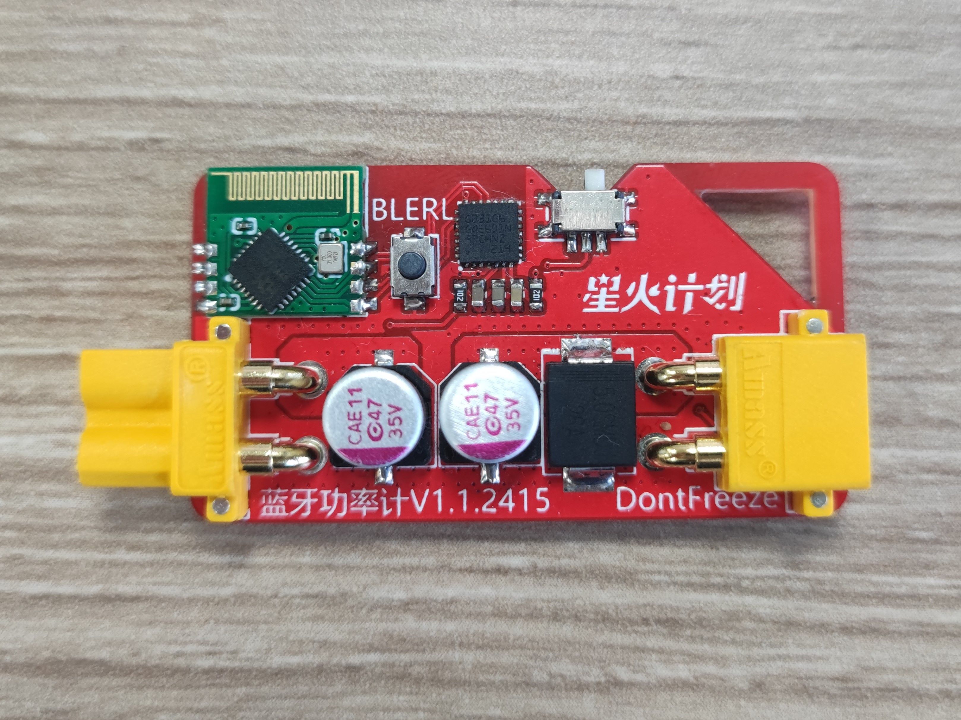
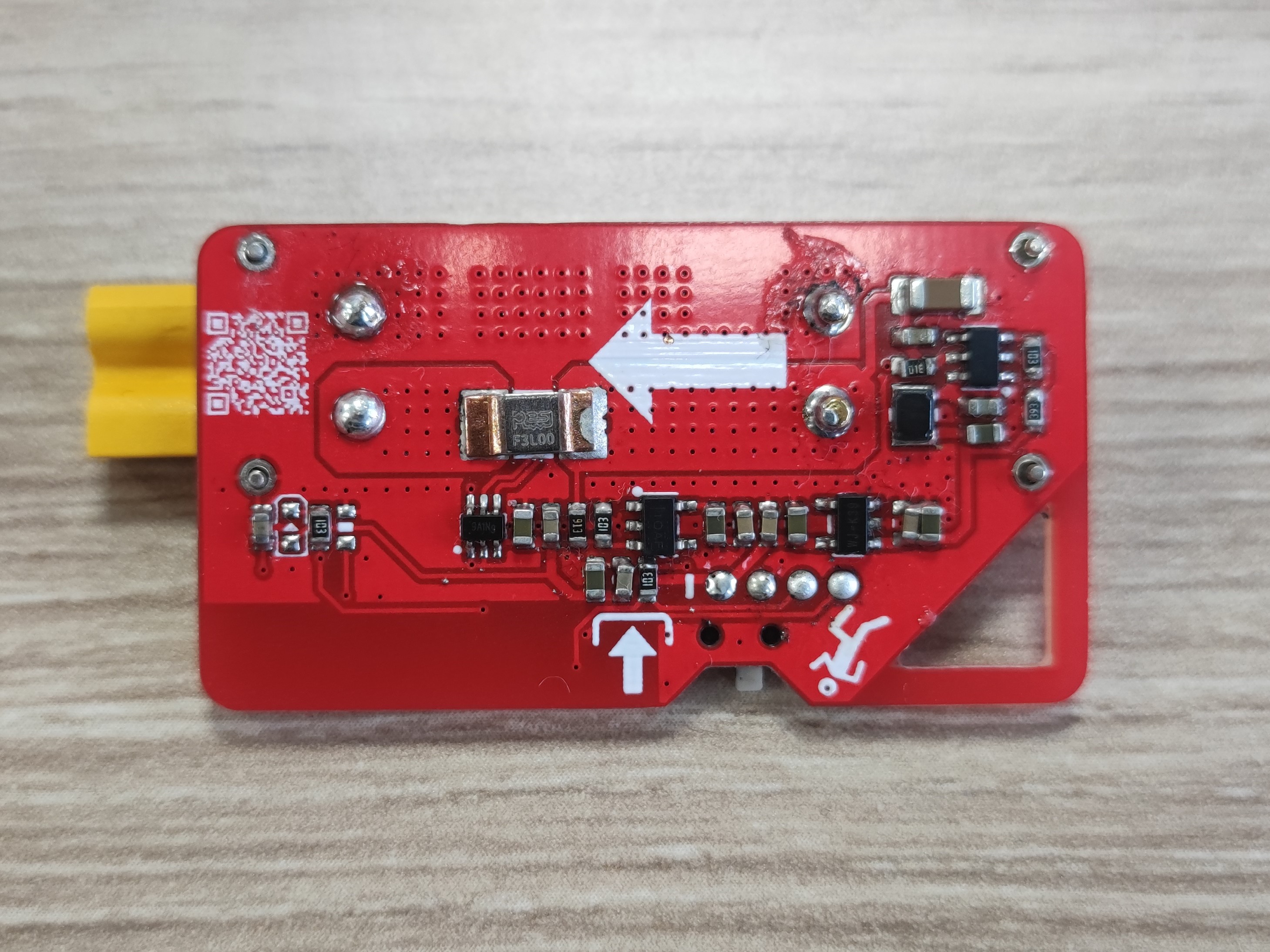
Bluetooth power meter
A wireless power meter using a Bluetooth serial port pass-through module
Project Description:
When debugging equipment with sudden load changes, such as motors, it's necessary to monitor voltage, current, and power variations to prevent undervoltage protection due to power fluctuations or overcurrent protection due to excessive instantaneous current. This requires a power meter with a sufficiently high sampling frequency that can graphically display parameter changes. The final solution uses the CH9140 Bluetooth serial port pass-through module for data transmission. Firstly, it allows the use of various serial port assistants as a host computer, flexibly utilizing their plotting, saving, and even other scripting functions. Secondly, Bluetooth transmission completely isolates the high-power power supply from the computer, ensuring the computer won't explode due to load failure (the downside is that the Bluetooth signal seems weak; a different wireless module may be considered later).
Open Source License:
This project is open source under the CC BY-SA 4.0 license. Reproduction is permitted, but please indicate the original link and author; commercial use is permitted, but please indicate the original link and author; if you modify and distribute this project (open source), please use the same open source license.
Project-related functions
: Voltage range: 5-30V (cannot be too low because the LDO output voltage will be inaccurate); Voltage
resolution: 0.1V
; Current range
: 0-20A; Current resolution: 0.1A; Sampling frequency:
4kHz (then averaged eight times);
Refresh rate: 500Hz.
Project attributes:
This project is being publicly disclosed for the first time and is my original work. This project has not won any awards in other competitions.
Project progress :
The project completion rate has reached my expectations (roughly displaying voltage, current, and power).
Serial port current control was designed, but I don't know how to use it .
Due to the hardware limitation of BLE_SER_A_ANT, only a baud rate of 115200Hz can be used.
I cannot use Bluetooth serial port for wireless download; I don't know why.
Design principle:
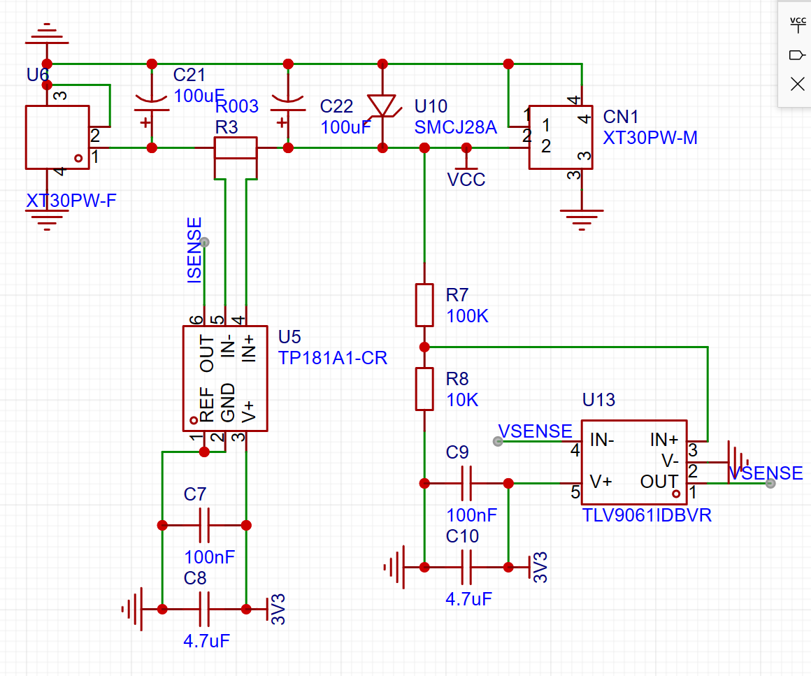
The current-sensing op-amp amplifies the differential signal of the voltage drop across the current-sensing resistor to a suitable voltage range that the microcontroller's ADC can read;
the voltage is divided by a resistor and then followed by a unity-gain stable op-amp for impedance transformation.
The above two signals are converted into digital signals by the ADC, and then linear fitting is performed to reconstruct the voltage and current signals.

There is a low-pass filter with a cutoff frequency of approximately 1kHz at the input port of the microcontroller's ADC. Although the sampling rate is set to 4kHz, it is used for oversampling before software averaging and filtering, so the final data refresh rate (transmission rate) is still 500Hz. For
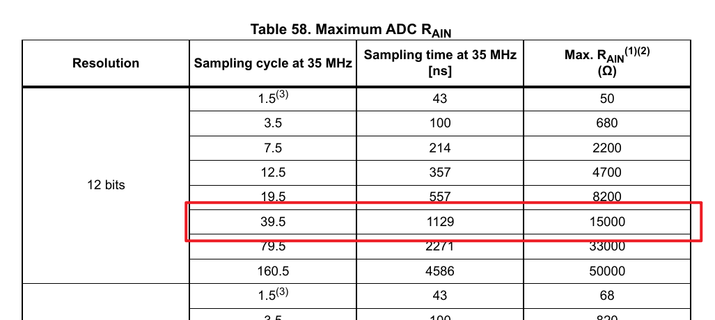
the ADC input RC filter resistor values, I referred to this table and approximately configured the ADC as shown in the red box, with an external resistor value of 10K.
In terms of software
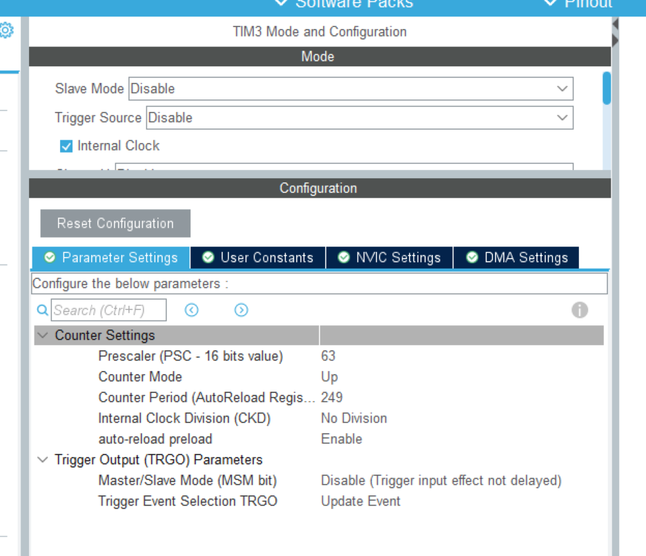
, I configured the timer to 4kHz to trigger ADC sampling.
There's not much else to say, just ADC sampling, averaging filtering, and serial transmission.
Since I don't use Keil for STM32 program development, please refer to my column for VSCode environment setup:
[A Brief Discussion on Developing STM32 HAL Library Using VSCode + EIDE Plugin + CubeMX - Bilibili]
Design Notes :
The version using the BLE_SER_A_ANT module can only transmit at a fixed baud rate of 115200; this is a hardware design issue with WCH. This resulted in 1.2ms taking up time to send just 14 characters, forcing me to adjust the update rate to 500Hz.

There was also packet loss during serial transmission for some unknown reason, causing the VOFA+ curve to fluctuate when receiving abnormal data.
This switch was originally intended for serial wireless downloading, but for some reason it's not working.
(Physical demonstration)
BLEPowerMeter.zip
PDF_Bluetooth Power Meter.zip
Altium_Bluetooth Power Meter.zip
PADS_Bluetooth Power Meter.zip
BOM_Bluetooth Power Meter.xlsx
91196
electronic


 京公网安备 11010802033920号

 CFC-4
CFC-4


