Fixed an issue where the I2C bus would occasionally be stuck when the I2C tool read registers.
Open source shell .
Fixed an issue where slow ACKs could occur in some cases, leading to the inability to recognize ACKs. Added I2C clock extension functionality.
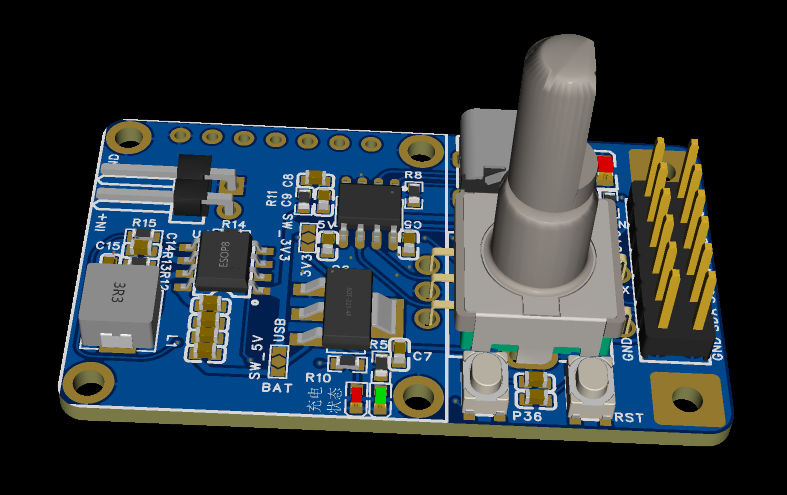
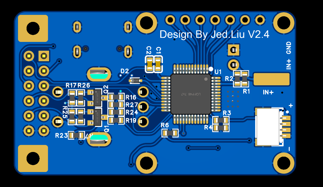
1. Based on the Lao Liu oscilloscope, retaining all functions of previous Lao Liu versions. Hardware has been miniaturized as much as possible, undergoing multiple revisions. Currently, the size is 28x48mm. To reduce height, a surface-mount EC11 encoder is used. Both surface-mount and through-hole EC11 encoders can be used; simply adjust the soldering position.
2. Uses the STC8A8K64D4 chip. The STC8A8K64S4A12 chip has increased significantly in price, but its functionality is essentially the same as the STC8A8K64D4.
3. Added the CH340N chip, enabling direct USB program download and serial port read/write.
4. An IP5306 charge/discharge management chip has been added, allowing for lithium battery connection and portability. In oscilloscope mode, the 35-second automatic shutdown function is not enabled when using battery power; a pulse is sent via the P36 interface to prevent automatic shutdown. In lithium battery mode, pressing the P36 button once powers on using lithium battery power, and double-clicking disables lithium battery power.
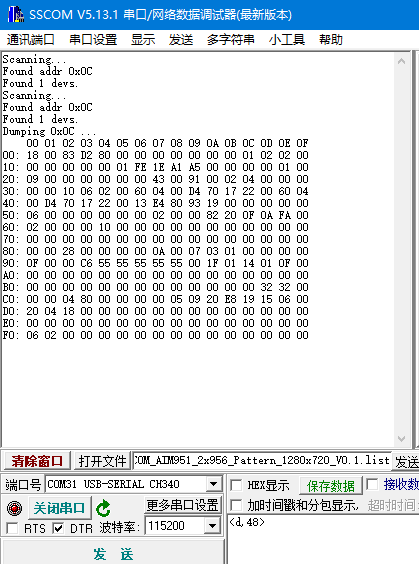
5. An I2C tool function has been added, supporting reading and writing to I2C devices and dumping. Delay is supported.
The write format is writing to device 0x0c, writing 0x01 to register 0x0a, with a 100ms delay.
The read format is reading the value of register 0x0B from device 0x0c. A 1000ms delay format is used for
dumping I2C devices, where 0c is the address of the device to be dumped. The
the baud rate provides help.
6. Upon power-up, the I2C tool function is entered by default and automatically scans for I2C devices. Once the device has been scanned, if a second scan is needed, press the P36 key or rotate the EC11 encoder. Pressing the P36 key once activates the IP5306, restarting the timer after 35 seconds and automatically powering off.
7. Press and hold the P36 key, then press the RST key again to automatically enter oscilloscope mode. In oscilloscope mode, there is no 35-second automatic shutdown limit when using battery function. When you press and hold the EC11 key and then exit, the 35-second automatic shutdown function will be automatically activated.
1. If you only want to experience the oscilloscope function and do not need other functions, you do not need to solder the corresponding components IP5306, CH340N, AMS1117, Q1, Q2 and corresponding peripheral components. There are corresponding soldering shorting points in the PCB. Shorting the two power supplies to +5V is sufficient.
2. Pins 1 and 2 of J6 need to be shorted together to power the MCU. The purpose of this pin is to ensure that the MCU is completely powered off during the first download; otherwise, the download will fail.
3. Shorting pins 5 and 7 of J6 together allows communication via USB->CH340N->STC microcontroller serial port. Removing this shorting allows pins 7 and 9 to be used as TTL tools.
4. If using the I2C tool function, pins 3, 4, and 6 of J6 are I2C level selection pins, supporting 3V3 and 1V8 levels.
5. The physical demonstration shows the PWR power button for IP5306; updated versions have merged it with P36 for easier use.
1. For the first download, use an external serial port tool. When downloading with an STC microcontroller, the serial port must be connected first, then the microcontroller must be powered on. Remember this order.
2. Download settings are as follows: IRC frequency selected as 27MHz.
3. Uncheck "Use the reset pin as an I/O port" so the RST button can be used as a reset button. Pressing this button again during the next download will automatically download.
4. Check "Add important test parameters at the end of the program area". It took me two days to recover from this mistake; the voltage readings are inaccurate if the oscilloscope function isn't enabled.
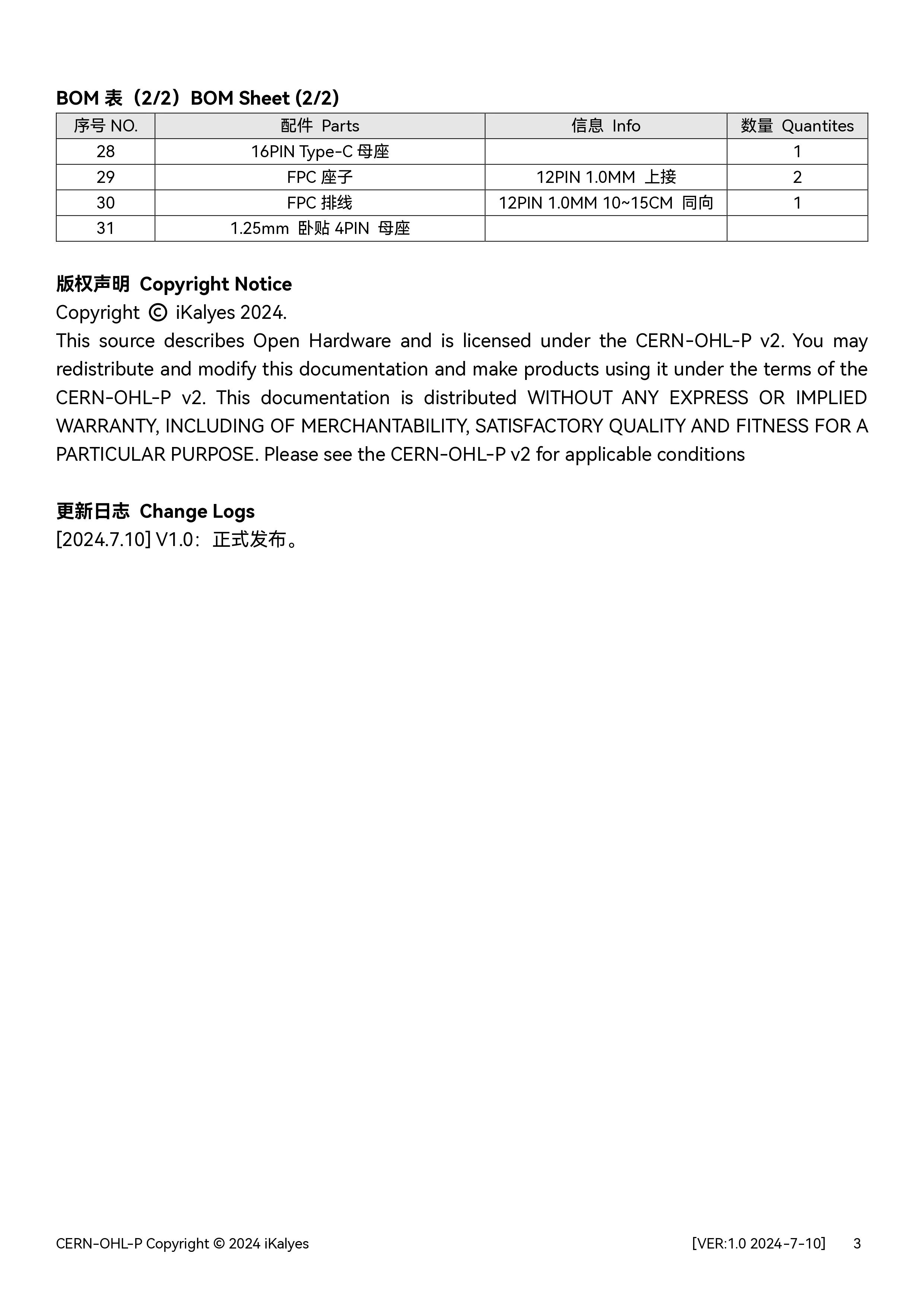
PDF_mini Portable Mini Oscilloscope DSO + I2C Tools + UART Serial Port Tools + Case.zip
Altium_mini Portable Mini Oscilloscope DSO + I2C Tools + UART Serial Port Tools + Case.zip
PADS_mini Portable Mini Oscilloscope DSO + I2C Tools + UART Serial Port Tools + Case.zip
BOM_mini Portable Mini Oscilloscope DSO + I2C Tools + UART Serial Port Tools + Case.xlsx
The protection board uses the BYD BM3451 lithium battery protection IC.
The board size is 20*70mm, compatible with 21700 lithium batteries.
By adjusting the components on the board, it can be compatible with 3S/4S/5S batteries.
Different suffixes of the IC model can be used to adapt to different charge/discharge cutoff voltages, and it can also be adapted to lithium iron phosphate batteries.
Adjusting the sampling resistor can adjust the protection current. The power
bank board uses the Ingenic IP5386 power bank chip . The peripheral
components are simple. The power bank board also achieves a size similar to the 21700 lithium battery. The
450kHz switching frequency far surpasses other solutions from both our own company and others, achieving lower ripple and a smaller inductor size.
The accessory is a 3D file of the casing; some holes require tapping. You can refer to another of my projects.
Note that from August 1, 2024, the sale of power banks requires mandatory 3C certification.

5386 casing.zip
PDF_IP5386 45W Power Bank.zip
Altium_IP5386 45W Power Bank.zip
PADS_IP5386 45W Power Bank.zip
BOM_IP5386 45W Power Bank.xlsx
91203
#9th LCSC Electronics Contest# Temperature and Humidity Detector
I am very happy to participate in the training camp for temperature and humidity detectors of the 9th LCSC Electronic Design Contest. I have always wanted to try making a temperature and humidity meter myself, but I have been struggling because there is no complete tutorial and I don't know where to start. This time, being able to try it out with the help of the training camp is a great opportunity.
1. Project Function Introduction
This desktop temperature and humidity meter project in the training camp uses the STM32G030K6T6 chip as the main control chip. This chip uses an Arm Cortex-M0+ core with a maximum clock speed of 64MHz.
It has 32KB of Flash and 8K of SRAM, and the power supply voltage is between 2.0V and 3.6V.
Basic code generation and configuration can be performed using this chip through the STM32CubeMX software. The graphical interface allows for quick and easy use of the chip, which is very user-friendly for beginners like myself.
This temperature and humidity meter can achieve high-precision temperature and humidity detection and operates in a low-power mode, saving energy.
2. Hardware Section:
2-1 Overall Schematic Design:

Project Overall Schematic
2-2 Main Control Circuit:

The main control MCU
circuit is powered by the ferrite bead in L1 and capacitor C2, achieving filtering to ensure a clean power supply for the MCU. The peripheral pin connections of the main control MCU should follow the pin definitions in the product manual. It is important to note that pins with specific functions should be used for their designated functions. For example, if the sensor connection requires the I²C function, then a pin with the I²C function should be used. This facilitates future pin usage.
2-3 Crystal Oscillator Circuit:
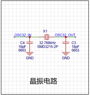
The crystal oscillator circuit
uses a 32.768kHz clock crystal to provide timing for the RTC, enabling the temperature and humidity detector to have a timing function, facilitating future functional expansion.
2-4 Temperature and Humidity Sensor Circuit: The core component of this project is the SHT40 temperature

and humidity sensor module
. The SHT40 is a fourth-generation, high-precision, ultra-low-power 16-bit relative humidity and temperature sensor manufactured by Sensirion. Its main characteristics are: relative humidity accuracy of ±1.5%RH, temperature accuracy of ±0.1℃, average operating current of 0.4μA, idle current of 80nA, and operating range of 0-100%RH, -40-125℃, meeting daily temperature and humidity measurement needs.
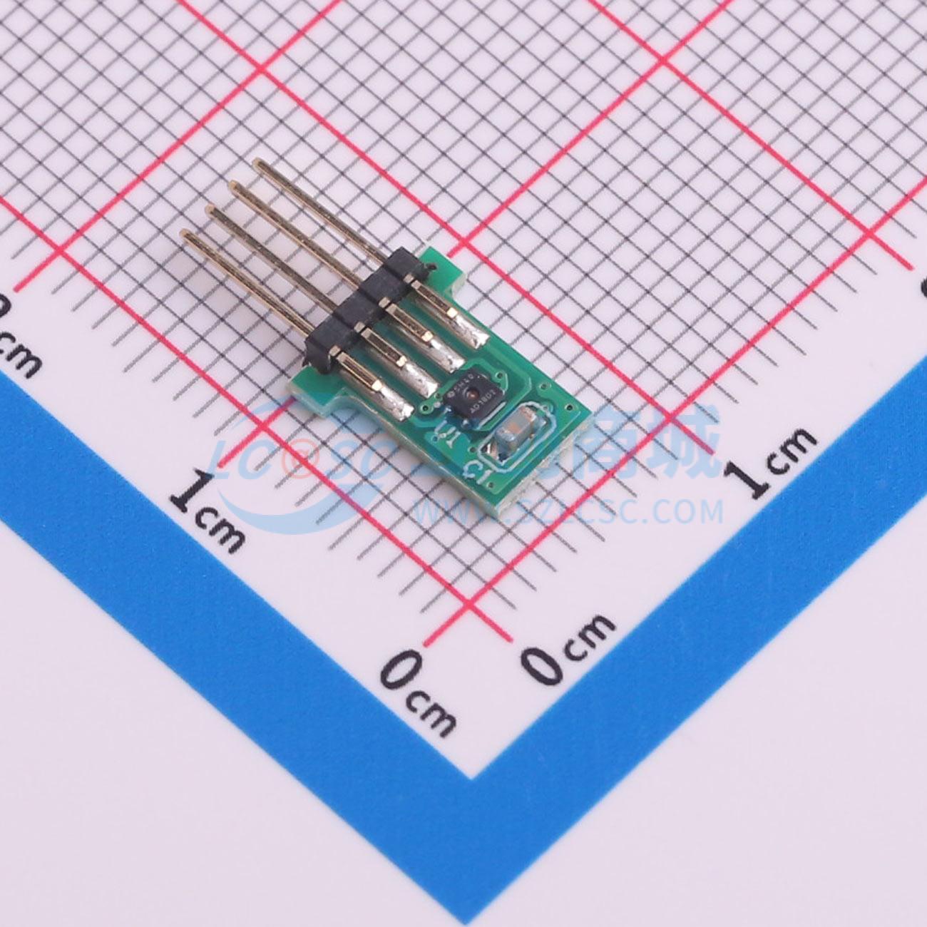
Because
the SHT40 is very small and difficult to solder, the SHT40 module specifically provided for this competition was used for ease of use. A crucial point to note is that the pins and sockets of the SHT40 temperature and humidity module must be correctly connected. Incorrect connection can affect measurement accuracy or even burn out the module!
2-5 Tri-state Output 8-bit Shift Register Circuit: To illuminate multiple digital tubes, an SN74HC595PWR
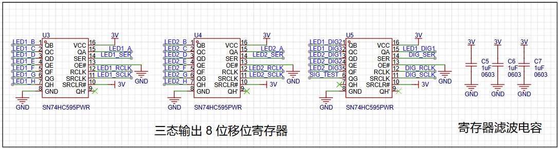
register is used to connect to the digital tubes for display. Multiple LEDs on the LED digital tube can be controlled via a single pin of the MCU
. It's important to note that if the digital tube display is incomplete or malfunctioning during later soldering, it's highly likely due to solder bridging or improper soldering of the register pins. Resoldering and checking the pin connections are necessary.
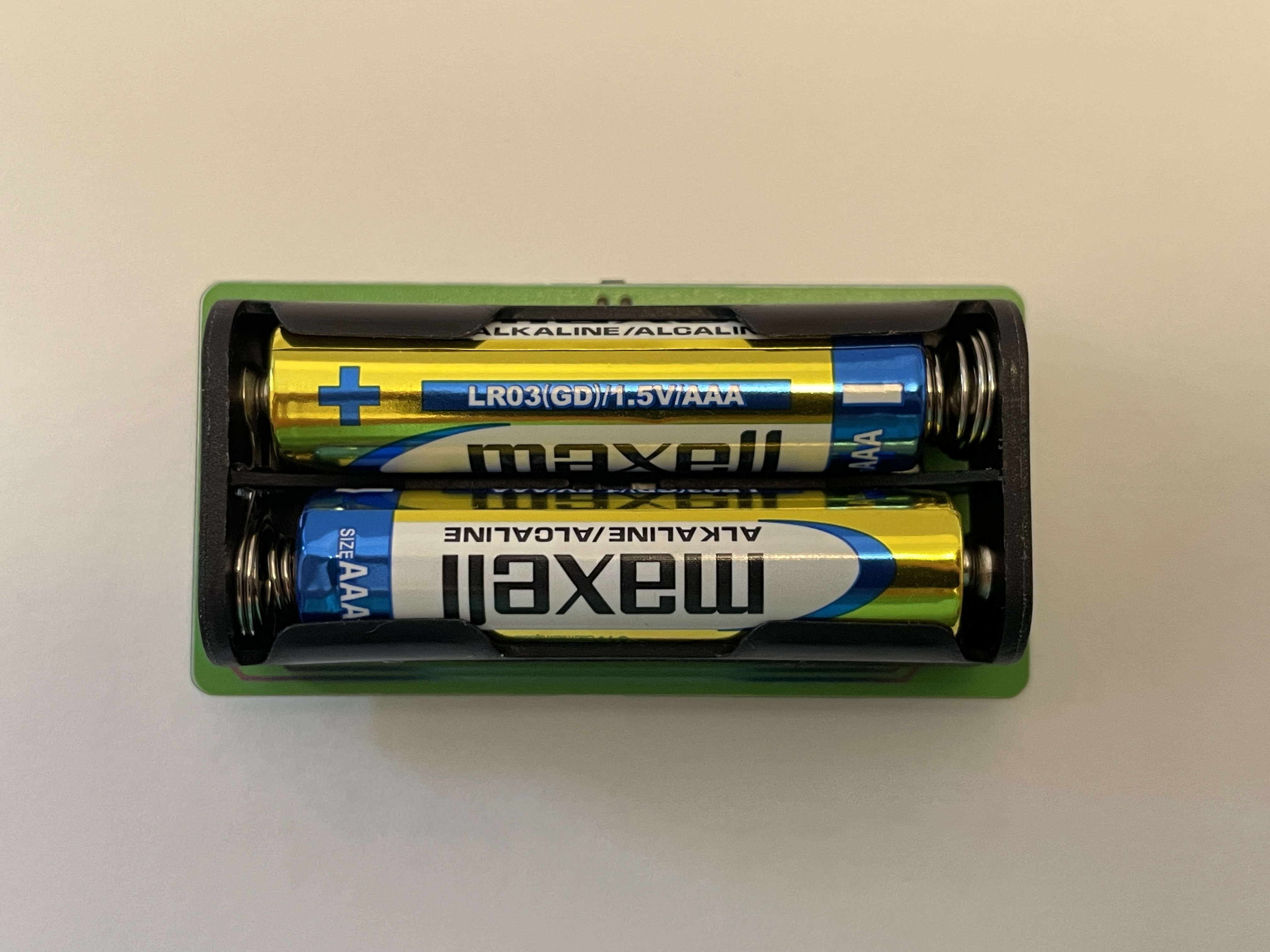
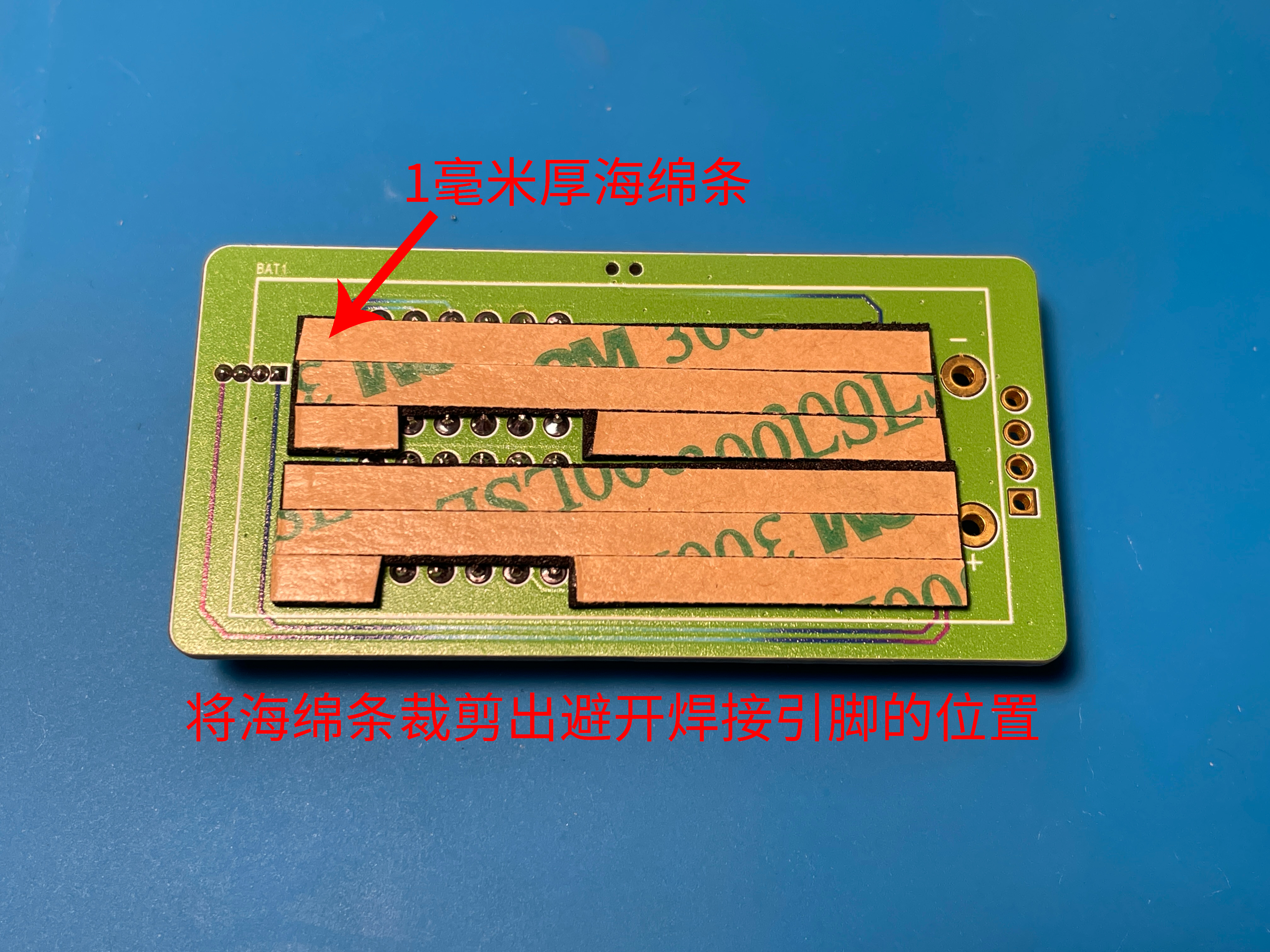
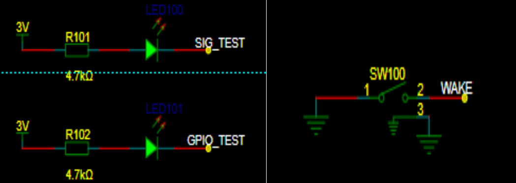
2-6 Wake-up Button Circuit: To achieve low power consumption and energy-efficient long-term operation of the temperature and humidity detector, a dedicated wake-up button is used. This allows the device to be woken up when temperature and humidity display is needed, and enters a low-power standby state when not in use. The button should be placed near the edge of the board for easy access. 2-7 Test LED Circuit : To facilitate later software debugging, two LEDs are used for testing and debugging of the software code. 2-8 Digital Tube Circuit: This circuit uses two 0.28-inch common-cathode 3-digit digital tubes to display temperature and humidity respectively. The LEDs come in various colors, which can be selected according to preference. 2-9 Battery Power Measurement Circuit: This circuit measures the battery voltage by collecting data, providing an extension function for displaying the battery level later. However, a reference voltage is needed for the MCU to compare the measured power level. Since there is no standard reference for comparison, the power measurement is inaccurate. For more accurate power measurement, consider replacing the MCU with one that has a built-in reference voltage ADC. 2-10 Battery Circuit: The battery power supply section uses two AAA batteries to power the entire system. To prevent reverse connection damage to the I/O ports, a WST3401 is used for reverse connection protection, protecting the chip's I/O ports. 2-11 Debugging Interface: This circuit uses an external SWD debugging interface for software debugging of the entire project. It's important to note that for easier installation of the casing later, this 1x4p header doesn't need to be soldered; it can be held in place by a programmer for downloading and burning code. 3. PCB Display 3-1 PCB Overall Layout and Routing The overall layout is compact, with all resistors and capacitors using the small 6030 package, further reducing the board size. 3-2 PCB 2D View PCB Front View PCB Back View This PCB was manufactured using JLCPCB's color silkscreen printing process, providing a more attractive appearance. The overall PCB uses Sensory's signature green as the main color, accented with JLCPCB's blue, making it more eye-catching and beautiful. The PCB traces are also drawn using a color gradient, giving the board a more technological feel and clearly showing the connections between components, facilitating measurement of pin soldering during later soldering. There was a small hiccup here: initially, the component silkscreen was changed to green, the same color scheme as the board, which made it visible on the screen, but difficult to see in the actual printed result. So, I changed the component silkscreen back to white for easier soldering. 3-2 PCB 3D View PCB Front View PCB Back View One point to note here is that the 4P header of H1 can be left unsoldered, which makes it easier to install the casing later. You can use a programming clip or other methods to connect to the debugging interface for downloading and debugging. 3-3 PCB Soldering Completed Object View PCB Front View When soldering the power socket on the back, you can use a sponge strip to pad the base, which will make the battery holder fit more flatly on the PCB. Back Sponge Strip Diagram 4. Software Part 4-1 Software Preparation The software part uses STM32CubeMX software to generate the basic framework. When using STM32CubeMX software, you need to register an account before you can install and download the software. Basic Usage of STM32CubeMX Software Log in to your account first to use the software .


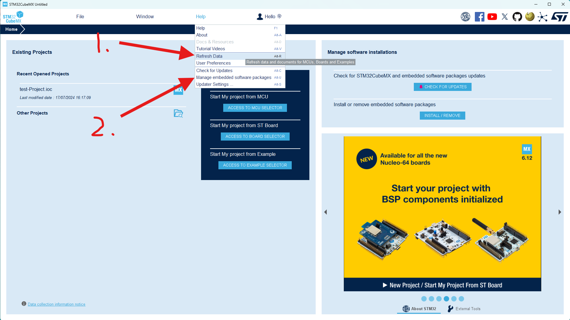
After logging into your account, first click the "Update Data" option under "Help" to ensure the software data is up-to-date, then click "2. Manage Firmware Packages".

Scroll through the list to find the STM32G0 series firmware package you're using and select the latest version to install.

Click "New Project" to begin creating our software code project.
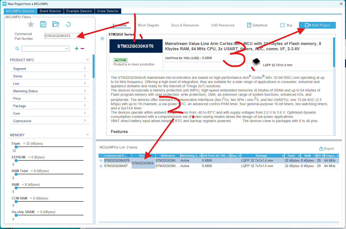
In the pop-up project window, select the STM32G030K6T6 chip you're using and create the project directly.
This completes the project creation. We'll then configure and call the chip's parameters within the newly created project.
4-2 Code Modification:
The code directly uses Chen's instructions, only modifying the button wake-up function.
Specific code modifications:
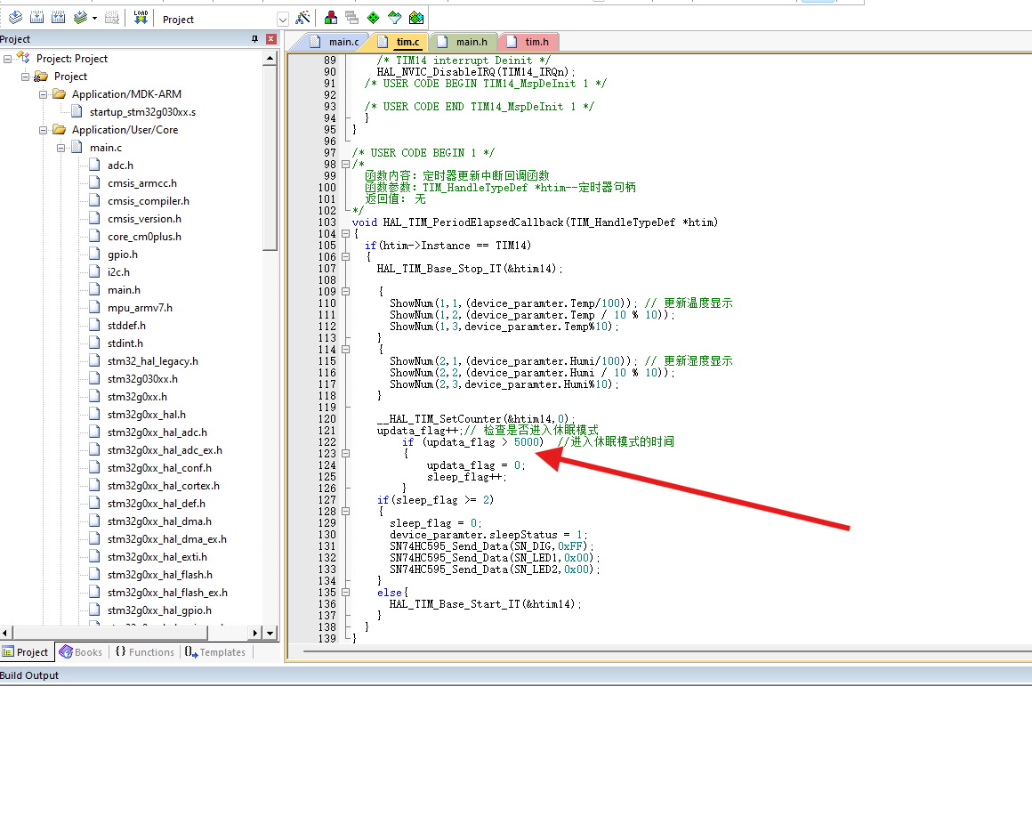
To display both temperature and humidity values simultaneously on the digital tube, we need to adjust the logic in the interrupt service routine so that the temperature and humidity display is updated with each interrupt, instead of alternating between them.
In this version, I made the following changes:
The conditional judgment for switching temperature and humidity displays using `updata_flag` was removed; instead, the temperature and humidity display is updated every time the interrupt service routine is triggered.
The logic for controlling the sleep mode using `update_flag` and `sleep_flag` is retained, but `update_flag` is no longer used in the display update section.
After this modification, the temperature and humidity values will be displayed on the digital tube every time there is an interruption, instead of alternating between displays.
The duration of the digital tube display can also be modified, allowing you to choose how long the digital tube should remain lit before entering sleep mode. I set it to enter sleep mode 5 seconds after the digital tube lights up. Regarding
the code burning in section 4-3, I used
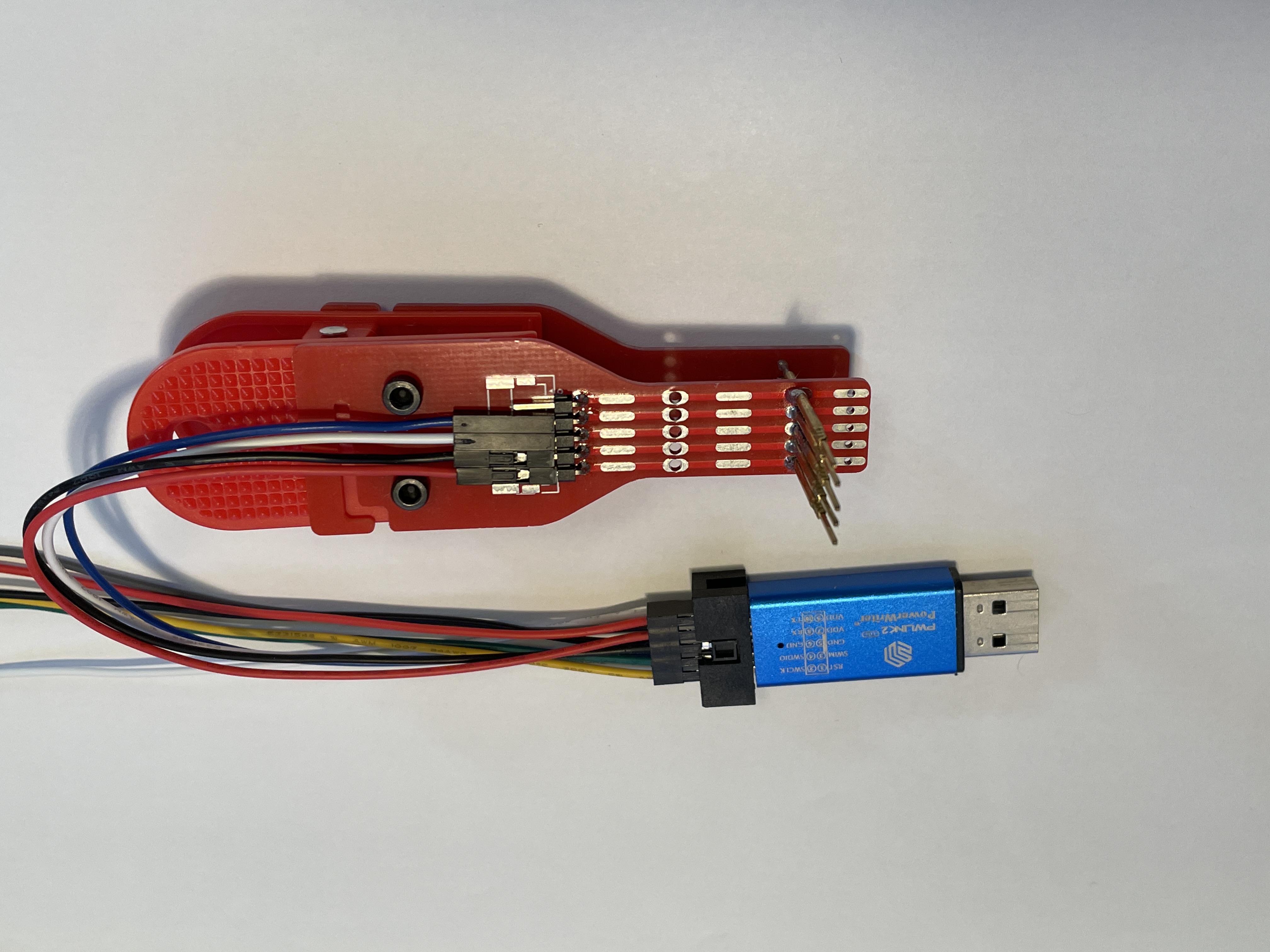
the PWLINK2 programmer and the programming clip.
The programmer I used is the PWLINK2, which is inexpensive and supports a wide range of chips. You can also use DAP Link or STLink if you have them. I only
used the PWLINK programmer here because I only had the PWLINK programmer. The programming clip is used here for easy placement into the casing later. The link to make the programming clip is here: Compatible Multi-Version Test Clip, Probe Clip, Programming Clip, Download Clip - JLCPCB EDA Open Source Hardware Platform (oshwhub.com). Using the programming clip is very convenient.
Points to note when programming: The first time you program the code, it will program directly. However, the second time you try to program, it might tell you that the board cannot be detected because the MCU has entered sleep mode. You need to wake it up by pressing a button before you can program the code.
Another issue I encountered when using PWLINK is that the following window pops up during programming. Follow the troubleshooting steps in

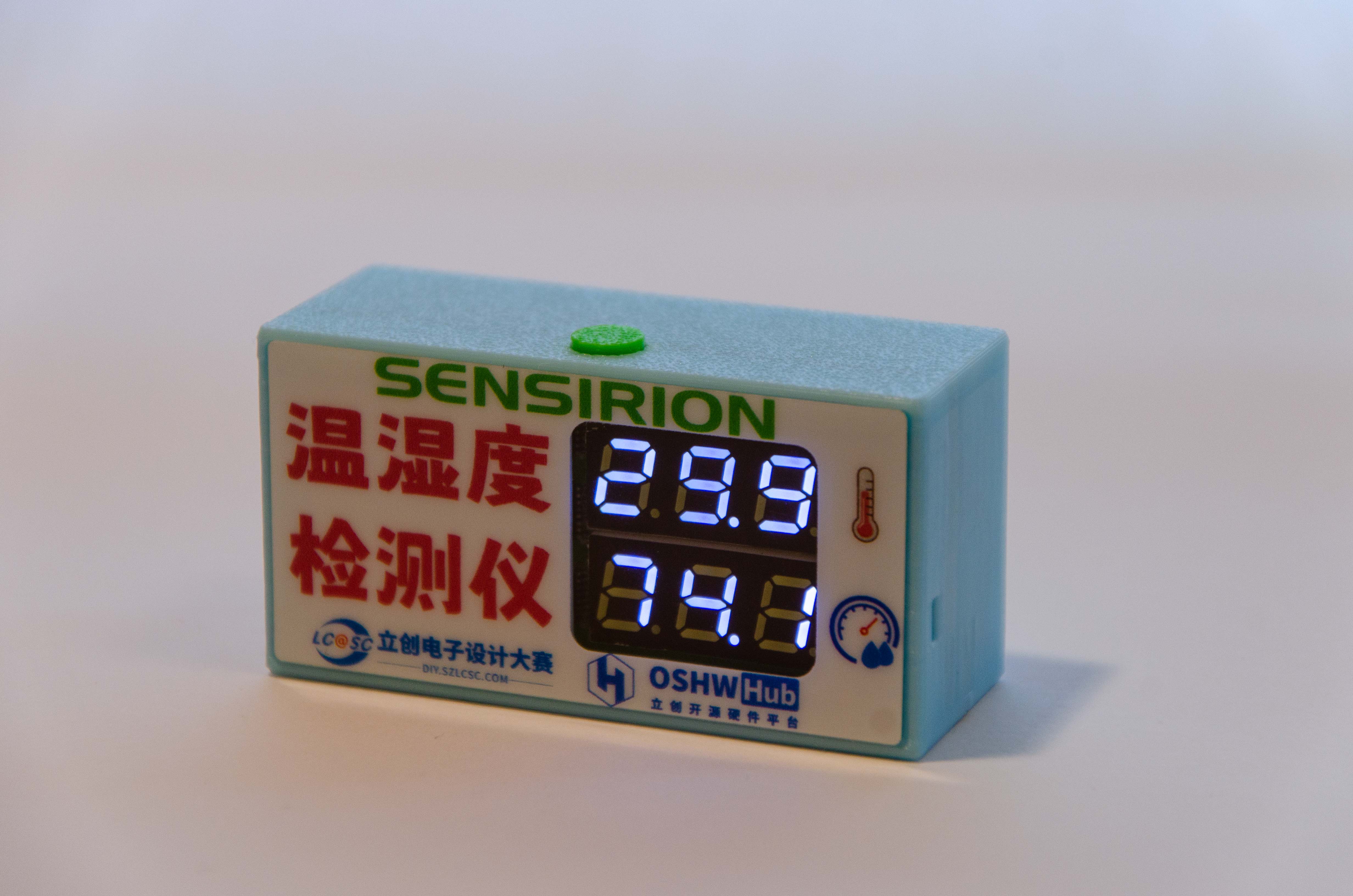
the pop-up window to resolve the issue, and you should be able to download normally. 5. Shell Part: Shell rendering image, actual product image, overall assembly diagram. The shell uses an embedded installation mode, with the PCB inserted through slots on the left and right sides. This avoids installing screws on the PCB, thus reducing the overall size of the PCB and making the finished product compact and aesthetically pleasing. The bottom plate of the shell is fixed to the top of the shell with two M2 screws. The top of the shell has a pre-drilled hole for an M2 heat-fused nut, which can be directly pressed into the hole without heat fusing (because the pre-drilled size is a bit large, haha). A hole is also made on the top of the shell to accommodate the wake-up button. Four simple panel designs were provided, and the files are included in the PCB design files. You can modify them to your liking. I chose PET material, printed on the bottom, with a thickness of 0.125mm. I didn't use adhesive backing because I didn't receive panel coupons this time, so I applied double-sided tape myself to save money; the effect is the same. 6. Competition LOGO verification PCB front PCB back 7. Project assembly demonstration video


Assembly demonstration video.mp4
PCB Color Silkscreen Printing Order File.zip
Panel order file.epanm
Temperature and humidity detector 3D shell file.zip
code.zip
PDF_#9th LCSC Electronics Design Contest# Temperature and Humidity Detector.zip
Altium_#9th LCSC Electronics Contest# Temperature and Humidity Detector.zip
PADS_#9th LCSC Electronics Design Contest# Temperature and Humidity Detector.zip
BOM_#9th LCSC Electronics Design Contest# Temperature and Humidity Detector.xlsx
91205
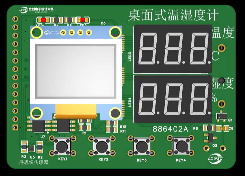
#9th LCSC Electronics Design Contest# Desktop Thermometer and Hygrometer
This project is the design of a desktop thermometer and hygrometer. Its main function is to detect the ambient temperature and humidity, and it can be set to provide temperature and humidity alerts. When the ambient temperature and humidity exceed the set values, the thermometer and hygrometer will issue an alert.
* 1. Project Function Introduction
This project is the design of a desktop thermometer and hygrometer. Its main function is to detect ambient temperature and humidity, and it can be set to provide temperature and humidity alerts. When the ambient temperature and humidity exceed the set values, the thermometer and hygrometer will issue an alert.
The project design concept is shown in Figure 1.

Figure 1 Overall Design Concept of Desktop Thermometer and Hygrometer The
functional modules are mainly divided into seven modules: temperature and humidity acquisition, temperature and humidity display, date and time display, battery power detection, temperature, humidity and battery alarm, low power mode, and temperature and humidity recording. A brief analysis of each of these seven modules is provided below.
1.1 Temperature and Humidity Acquisition
This project uses the Sensirion SHT40 temperature and humidity sensor. This sensor is small in size, high in accuracy, and easy to wire, making it very suitable for this project.
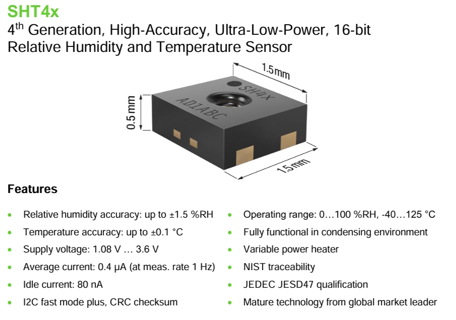
Figure 2 Introduction to Sensirion Sensors
1.2 Temperature and Humidity Display
This project plans to use two display methods: one is to use two three-digit LED displays, one showing the temperature value and the other showing the humidity value. This display is very intuitive. Another option is to use a 0.96-inch OLED display. This is because OLED displays offer richer content compared to digital tubes, and it also allows for human-machine interaction in conjunction with buttons, enabling functions such as setting temperature and humidity alarm limits, displaying date and time, and displaying alarm information.
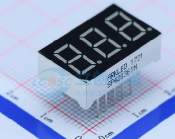
(Figure 3: Digital Tube;

Figure 4: 0.96-inch OLED Display
) 1.3 Date and Time Display and Battery Power Detection
The main control chip used in this project is the STM32G030K6T6. The date and time can be read using the chip's built-in TCR clock and displayed on the OLED screen.
This project uses two AA batteries connected in series (resulting in 3V) to power the system. The battery voltage is detected by the STM32G030K6T6's ADC to determine the battery power.
1.4 Temperature, Humidity, and Battery Alarms:
Through a human-machine interface formed by buttons and an OLED display, the operator can input upper temperature, upper humidity, and lower battery limits. The alarm is judged by comparing these limits with collected temperature, humidity, and battery levels. If the set alarm values are exceeded, the main controller controls the LED to flash and the buzzer to sound (which can be turned on or off in the settings), and displays the alarm information on the OLED display.
1.5 Low Power Mode :
This project plans to design three operating modes:
Low Power Mode: No information is displayed; the system enters sleep mode.
Normal Mode: OLED display, digital tube does not display.
Highlight Mode: OLED and digital tube display simultaneously.
1.6 Temperature and Humidity Recording:
This function is an extension function, with a reserved AT24C64 memory chip. It can be designed to store daily temperature and humidity data, with the storage time and frequency set. The hardware is reserved; the program will be developed as needed.
*2. Project Attributes:
This project is the first public disclosure by an individual. The principle design references the official schematic diagram from the LCSC training camp, the PCB design is self-designed, and the program is adjusted based on the LCSC training camp program to achieve the self-designed functions.
* 3. Open Source License
GPL 3.0
* 4. Hardware Section
4.1 Circuit Principle Design
The hardware section mainly consists of 11 parts: power supply circuit, main control circuit, crystal oscillator circuit, temperature and humidity sensor, digital tube display circuit, button circuit, LED circuit, buzzer driver circuit, OLED display circuit, EPROM driver circuit, and IO interface circuit.
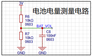
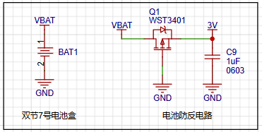
4.1.1 Power Supply Circuit:
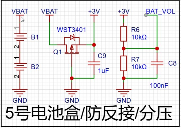
Figure 5 shows the power supply circuit
system, which is mainly powered by a 3V voltage obtained from two AA batteries connected in series. After the voltage is output, a field-effect transistor is connected to prevent reverse voltage connection. Two 10K resistors are used to divide the voltage between 3V and ground. The ADC of the microcontroller is used to collect the voltage to determine the battery level.
4.1.2 Main Control

Circuit Figure 6 shows the main control circuit.
The main control chip is STM32G030K6T6. After the main power supply of 3V comes in, a ferrite bead is used to remove interference before powering the microcontroller.
4.1.3 Crystal Oscillator

Circuit (Figure 7)
: The STM32G030K6T6 has an internal crystal oscillator, but an external 32.768kHz crystal oscillator is used to obtain a more accurate clock signal.
4.1.4 Temperature and Humidity Sensor, OLED Display Circuit, and EPROM Driver
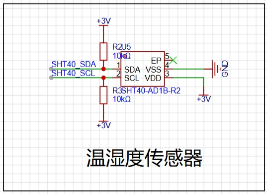
Circuit (Figure 8: Temperature Sensor

Circuit; Figure 9: 0.96OLED
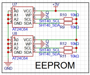
Circuit; Figure 10: EEPROM
Circuit): The temperature and humidity sensor, OLED display circuit, and EPROM driver circuit all communicate with the STM32G030K6T6 via I2C. Refer to the chip manual for connection instructions.
Note: The AT24C64 schematic shows two chips; only one chip should be soldered in actual use, with the other as a spare (address conflicts may occur).
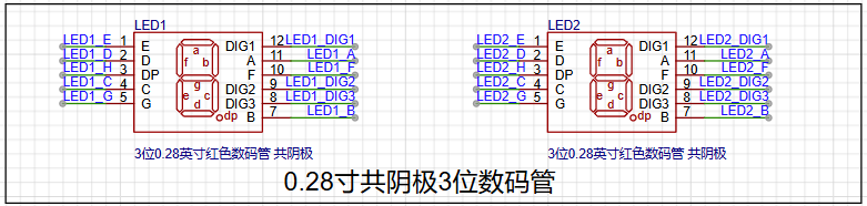
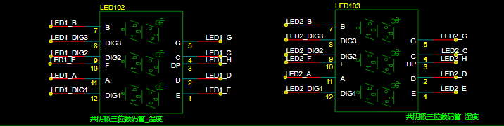
4.1.5 Digital Tube Display
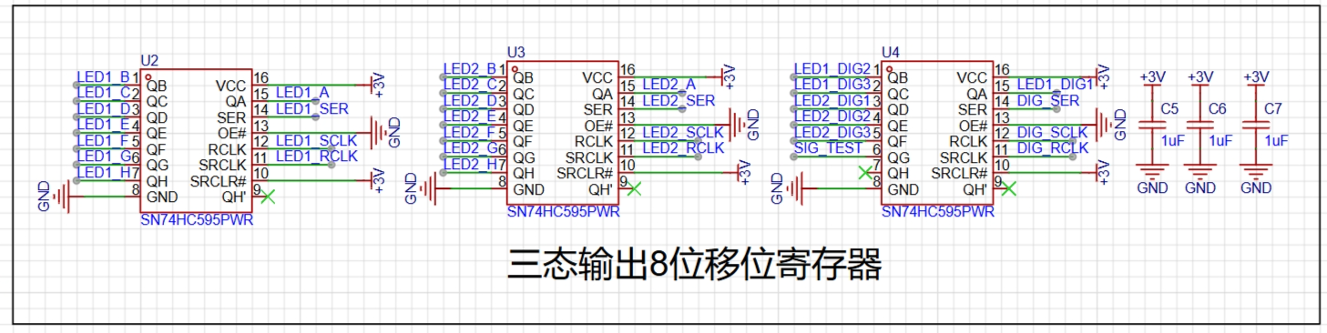

Circuit (Figure 11): The digital tube display circuit
uses two 3-digit common cathode digital tubes, controlled by an 8-bit shift register with tri-state outputs to reduce the I/O usage of the STM32G030K6T.
4.1.6 Button Circuit, LED Circuit, and Buzzer Driver
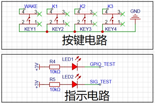
Circuit Figure
12)
The button circuit, LED circuit, and buzzer driver circuit are all simple IO high/low level control circuits. Refer to the schematic diagram and connect them to the STM32G030K6T's IO.
4.1.7 IO Interface
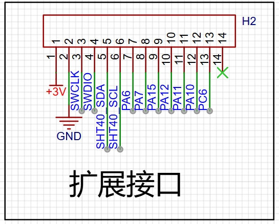
Circuit (Figure 14) The IO interface
brings out the unused IO ports of the STM32G030K6T for easy program download and expansion.
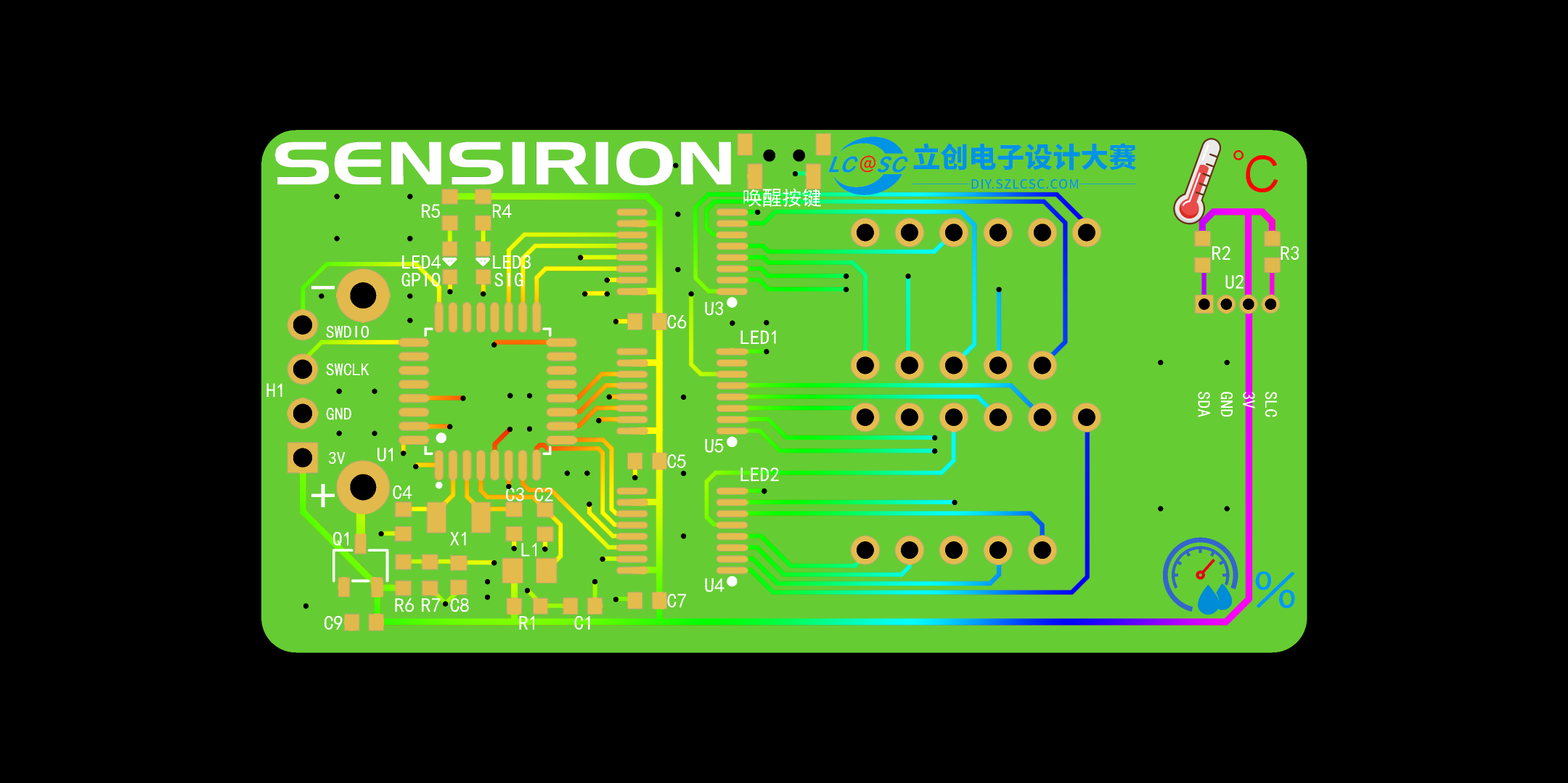
4.2 PCB Design
The PCB layout is shown in the figure below. The digital tube is placed on the right side of the circuit, the OLED display on the left, and the buttons at the bottom for easy operation.
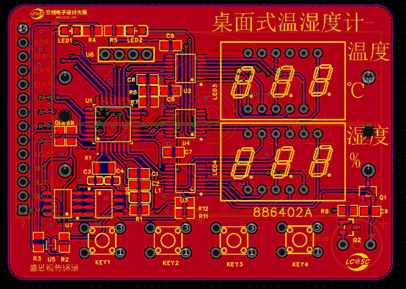
(Figure 15 PCB Layout)
(Figure 16 Circuit 3D Model)
The temperature and humidity sensor uses a chip, which is relatively small and has some soldering difficulty. For replication, a module can be chosen for easier soldering.
4.3 PCB Prototyping
After the PCB design is completed, you can place an order with JLCPCB. We are very grateful to JLCPCB for providing free prototyping.
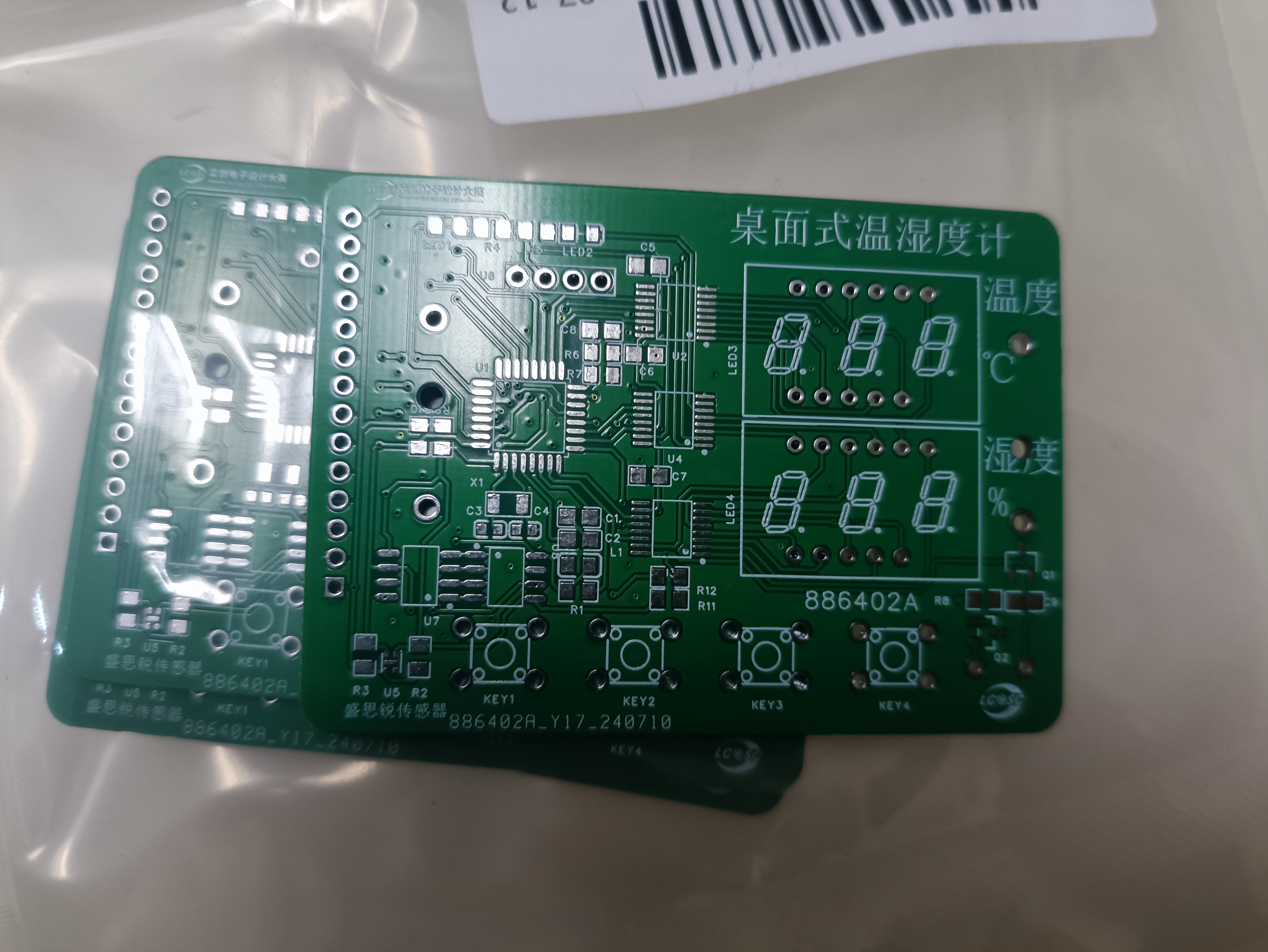
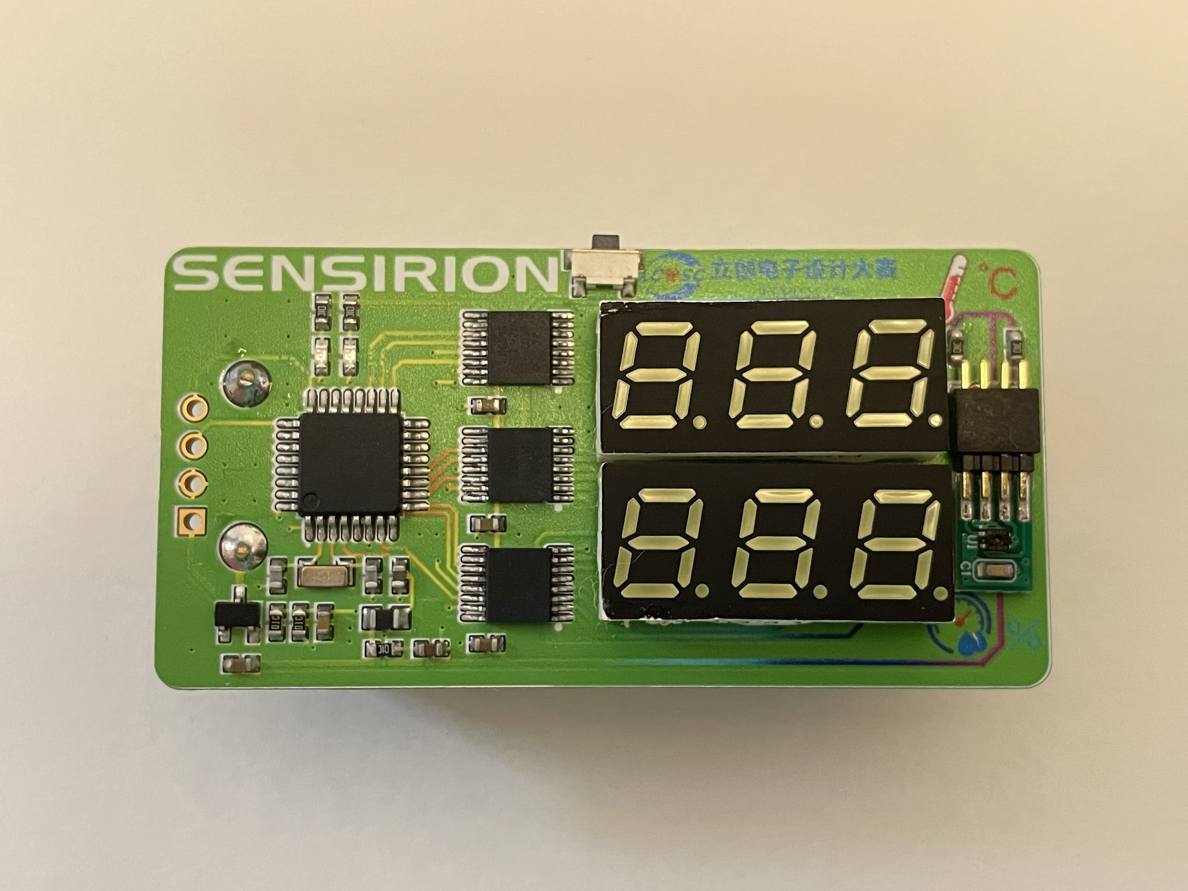
Figure 17 PCB Physical Image
4.4 Soldering
Students with 3D printing capabilities can export the PCB drawing as a DXF file, then stretch it in 3D design software (SolidWorks/Shapr 3D, etc.) to print it out as the PCB stencil.
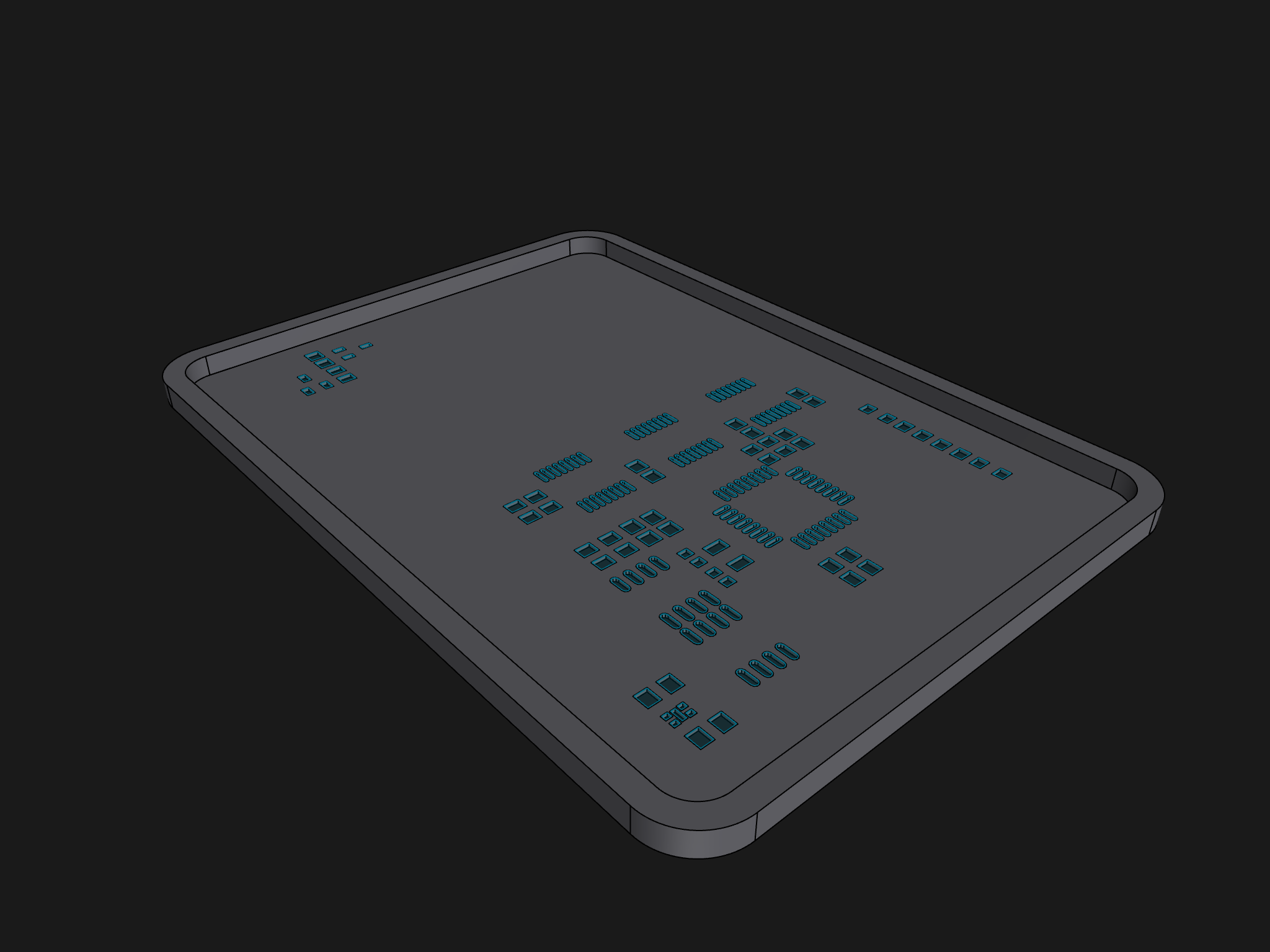
Figure 18 PCB Stencil Model

Figure 19 Soldering on the PCB
After installing the components, you can proceed to the soldering stage:
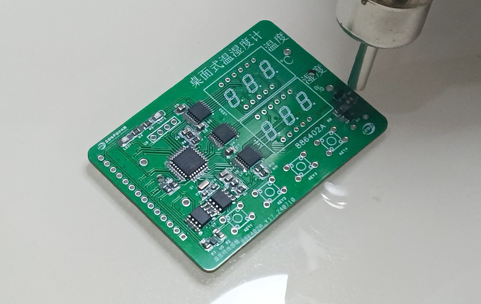
Figure 20 Soldering

Figure 21. Completed Welding Image
4.5 Housing Design The
housing design mainly considers the OLED display area, digital tube display area, button area, and temperature and humidity sensor area in conjunction with the PCB layout. See the following figures for the housing design:
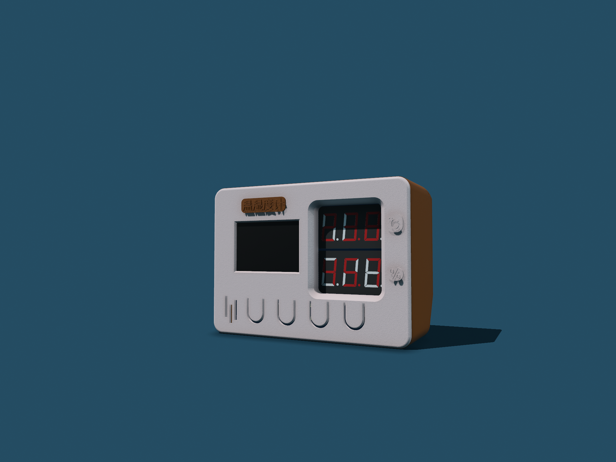
Figure 22. Housing Model Design Figure
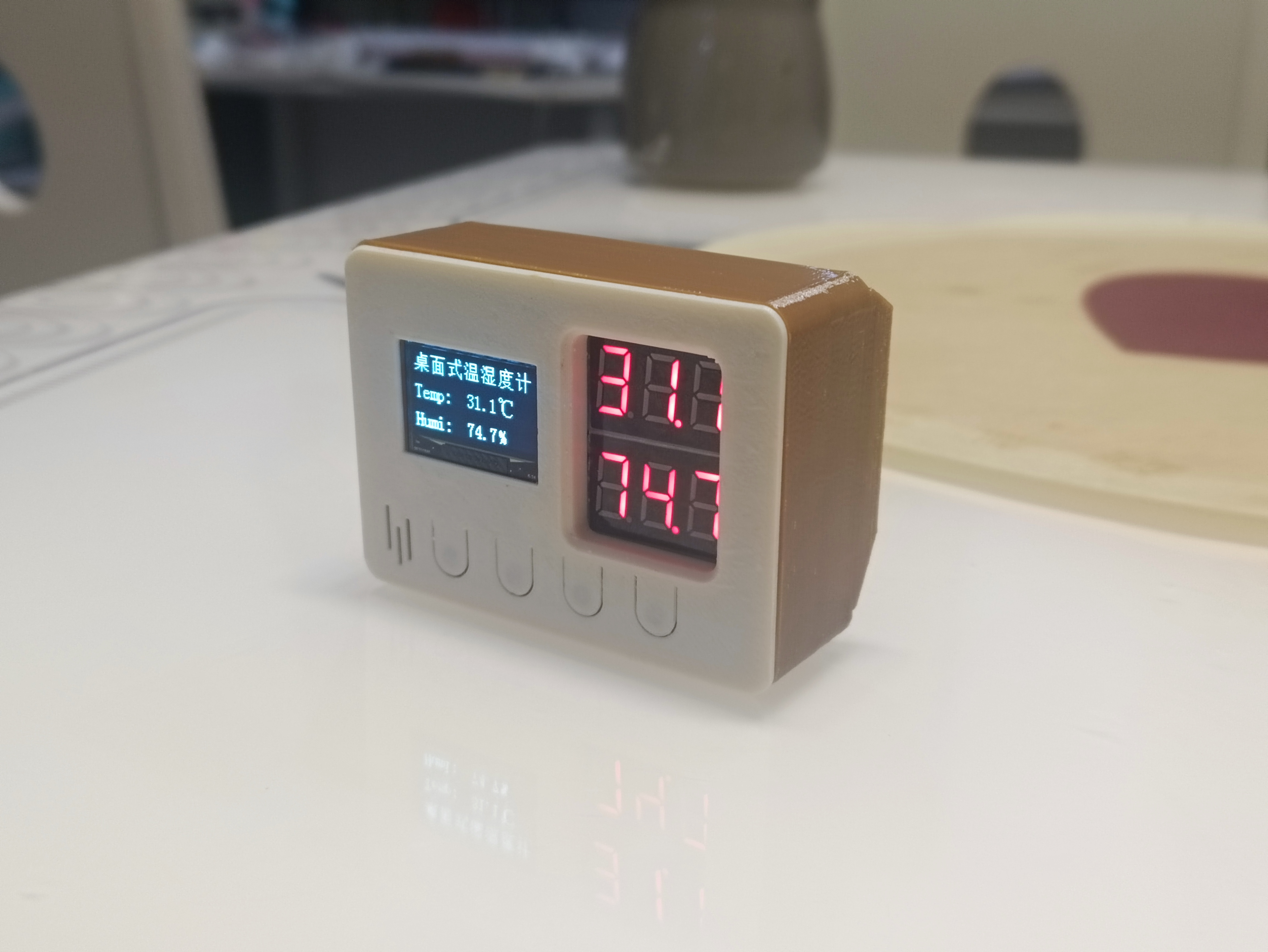
23. Housing Image
*5. Software Part
5.1 Design Idea
Based on functional requirements, the program part mainly aims to implement the following four functional modules:
temperature and humidity display (OLED display and digital tube display);
temperature and humidity alarm (temperature and humidity upper limit setting, alarm mode is LED flashing and buzzer beeping);
date and time display (the temperature and humidity meter is not connected to the network, and the date and time need to be manually calibrated);
mode settings (highlight mode, normal mode, low power mode).
The overall design idea is shown in the following figure:

Figure 24. Program Implementation Idea
5.2 Program Writing
The program writing mainly uses STM32CubeMX and Keil uVision5. Some configurations and programs are shown in the following figures. Detailed configurations and program code are in the attachment.

Figure 25. Chip Pin Configuration Diagram (Partial)

Figure 26. Program Code (Partial)
*6. BOM List
See the attached BOM list for details.
*7. Verification image of the competition logo
(Figure 27). A physical image of the circuit board containing the competition logo.
* 8. Demonstrate your project and record a video for upload
. See the attached demonstration video for details.
Desktop Thermometer and Hygrometer Demonstration.mp4
SHT40_Project_V1.6.zip
Desktop Thermometer and Hygrometer Housing.zip
PDF_#9th LCSC Electronics Design Contest# Desktop Thermometer and Hygrometer.zip
Altium_#9th LCSC Electronics Design Contest# Desktop Thermometer and Hygrometer.zip
PADS_#9th LCSC Electronics Design Contest# Desktop Thermometer and Hygrometer.zip
BOM_#9th LCSC Electronics Design Contest# Desktop Thermometer and Hygrometer.xlsx
91206
#9th LCSC Electronics Contest# Temperature and Humidity Detector
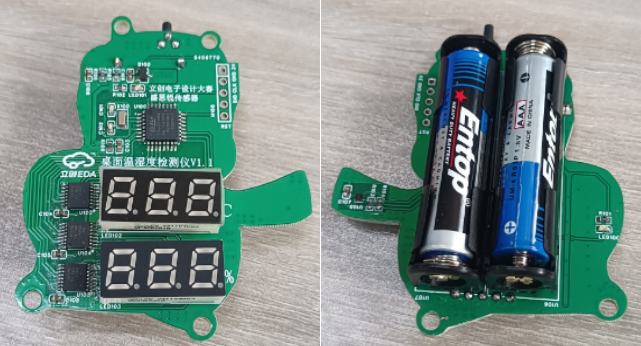
This is a desktop temperature and humidity sensor, shaped like a cow, built using the STM32G030K6T6 microcontroller and the SHT40 temperature and humidity sensor. It can measure ambient temperature and humidity and is suitable for homes, offices, laboratories, and other similar locations.
* 1. Project Function Introduction
1. Accurately, promptly, and without error measures the temperature and humidity of the current environment.
2. Clearly displays the current temperature and humidity values using two three-digit LED displays. 3.
Compact, exquisite, and aesthetically pleasing design, suitable for placement on desks and other desktops.
4. Uses common AAA batteries as a stable, reliable, and continuous power source.
5. Has a wide measurement range, capable of measuring temperatures from -40°C to 125°C and relative humidity from 0 to 100%.
The Little Cow temperature and humidity sensor can be used as a desktop ornament and can also measure the current ambient temperature and humidity.
*2. Project Attributes
: LCSC Summer Training Camp
*3. Open Source License:
GPL3.0
*4. Hardware

: Powered by two AAA batteries; CR2032 is reserved because the design uses a digital tube display, and we wanted to test whether the CR2032 can handle it. The sensor uses a 3V power supply and two 4.7K pull-up resistors.

STM32G030K6T6 microcontroller minimum system circuit includes power supply, crystal oscillator, reset, and download circuits.

SN74HC595PWR decoder is used. Two three-digit common cathode digital tubes are used, one to display temperature and one to display humidity.
LEDs for testing and a wake-up button are added.
1. Membrane: https://dos.szlcsc.com/home.html
2. Outer Shell (Select 3D Printing in JLCPCB Order Assistant)

Step 1:
Soldering the Circuit Board
1. Soldering the STH40 Sensor: First apply solder paste, place the sensor on the solder paste-covered area, and use a hot air gun to heat it.
2. Soldering can be done with a soldering iron during the rest of the process.
Note: Solder the SN74HC595PWR first, then solder the digital tube.
Step 2:
Downloading the Program:
Open the source program and connect the SWCLK, SWDIO, GND, and 3.3V in ST-LINK to the corresponding circuit boards. After successful download, power on again.
Note: Remember to install the ST-LINK driver.
Step 3:
Place the circuit board into the outer shell and tighten the (M3*6) screws as shown in the picture below.
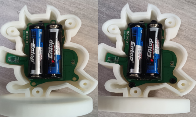
Step 4:
Cover the back cover and tighten the (M3*12) self-tapping screws. Finally, apply the film as shown in the picture below.
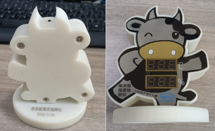
You can print various different colors for replication.

*5. Software Part
Training Camp Code
*6. BOM List
Assembly BOM
Item
No. Name
Remarks
1.
Little Bull Outer Shell Top Cover
2.
Little Bull Outer Shell Bottom Cover
3.
Film
4.
M3*6 Screws
Tighten Circuit Board
5
M3*12 self-tapping
screw casing
(see attachment
7), competition logo verification

, and demonstration of your project (record as a video and upload).
Little Cow Lid.STL
Desktop temperature and humidity meter print.ai
LCSC Electronics Contest: Desktop Temperature and Humidity Monitor - Video Demonstration.mp4
Niu Desktop Temperature and Humidity Monitor.STL
Desktop temperature and humidity meter code.zip
PDF_#9th LCSC Electronics Design Contest# Temperature and Humidity Detector.zip
Altium_#9th LCSC Electronics Contest# Temperature and Humidity Detector.zip
PADS_#9th LCSC Electronics Design Contest# Temperature and Humidity Detector.zip
BOM_#9th LCSC Electronics Design Contest# Temperature and Humidity Detector.xlsx
91207
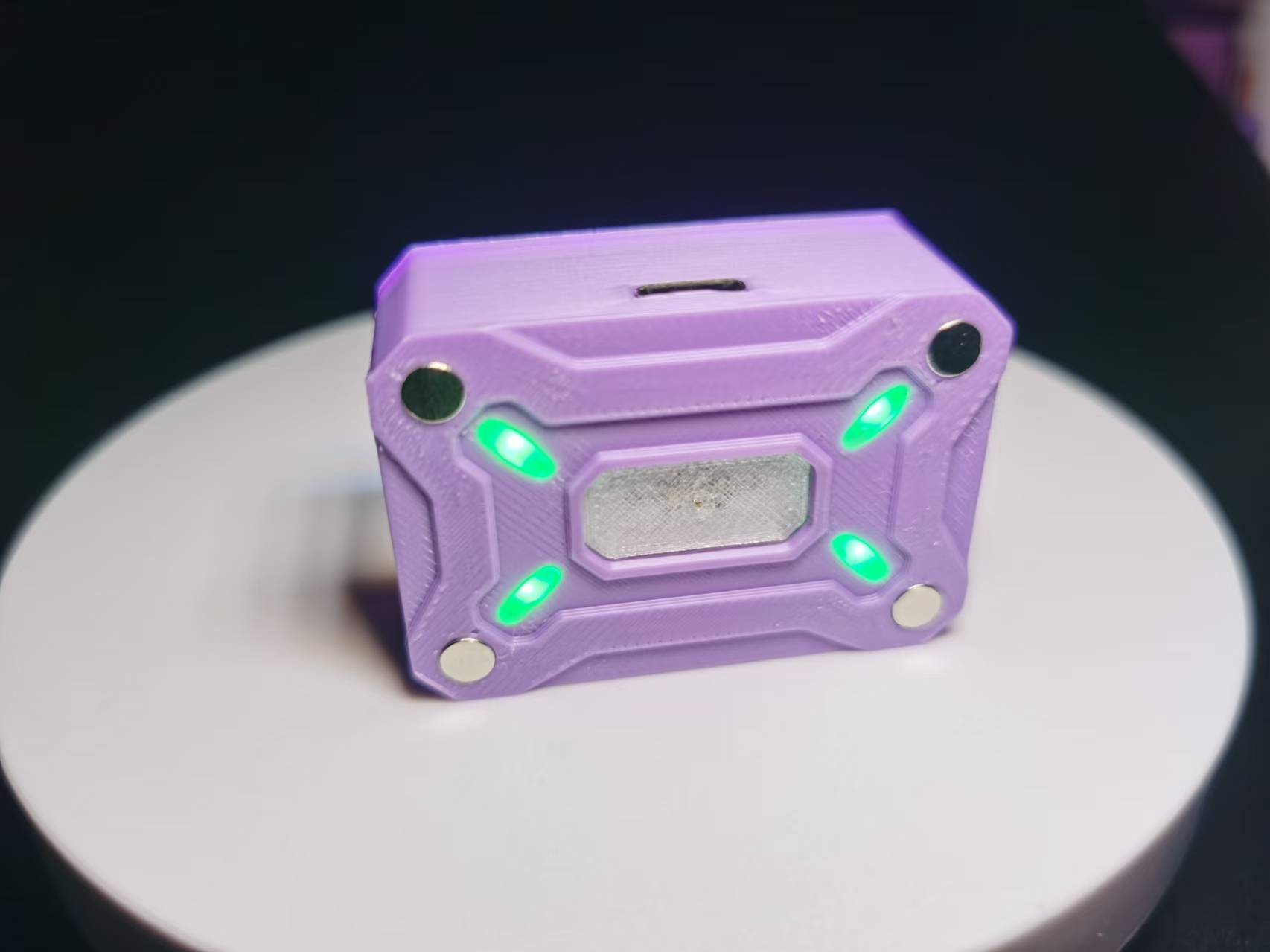
Mecha-style Pocket Light - Open Source
Based on the upgraded casing of the pocket fill light, it can be compatible with larger lithium batteries and has better heat dissipation!
Demonstration Video
Features:
Touch Switch,
Dual Color Temperature (Cool Light, Warm Light, Cool-Warm Light),
Stepless Dimming (with Memory),
Magnetic Attachment
【Features Supported】
1. Warm Light: 2700k; Cool Light: 13000k
2. Light Touch to Switch Modes: Cool Light - Warm Light - Cool-Warm Light 3. Long Touch: Brightness Adjustment in this mode
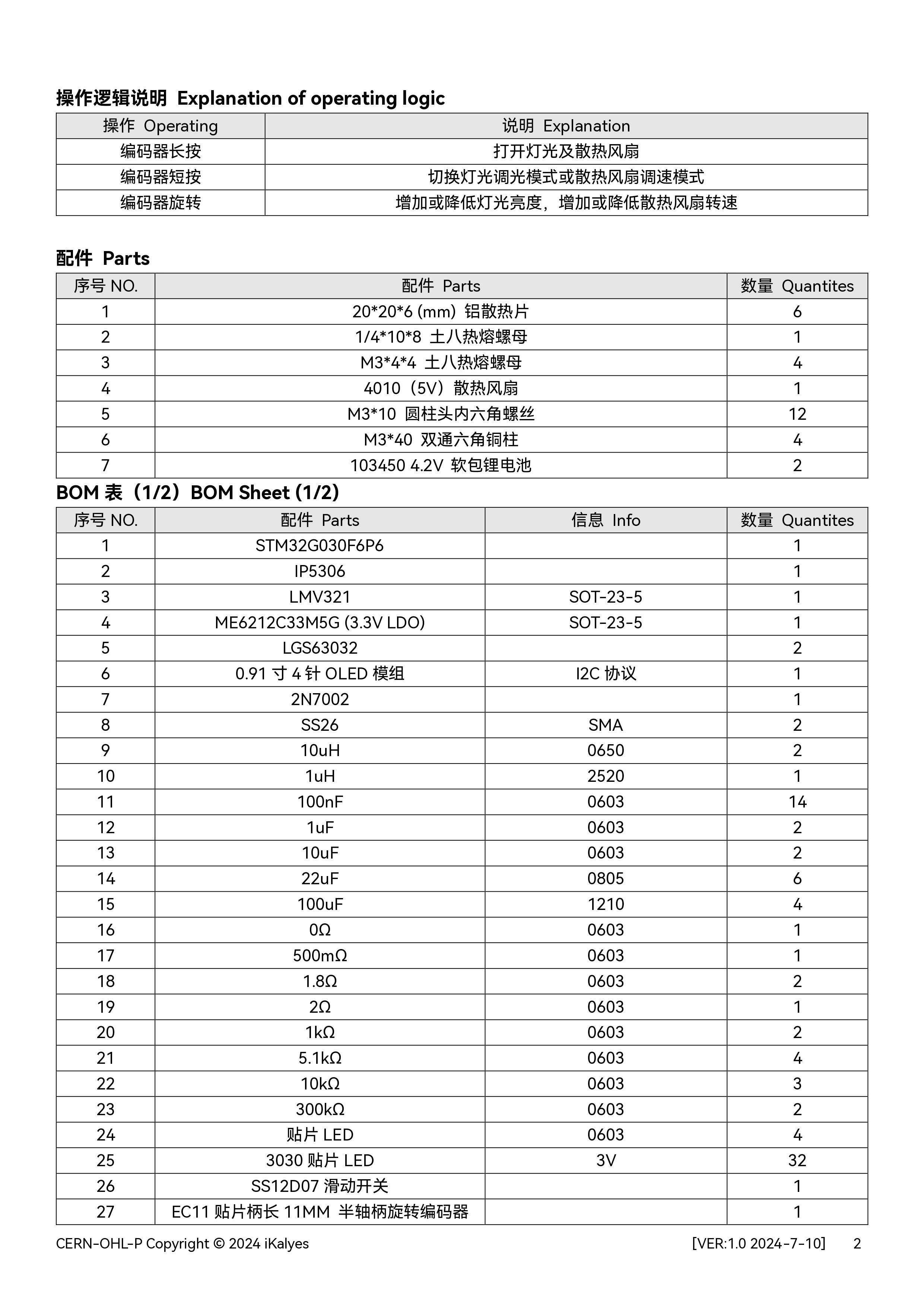
【Hardware Support】
1. Onboard TP4056 Lithium Battery Charging Protection Chip
2. Dual Color Temperature Stepless Dimming IC
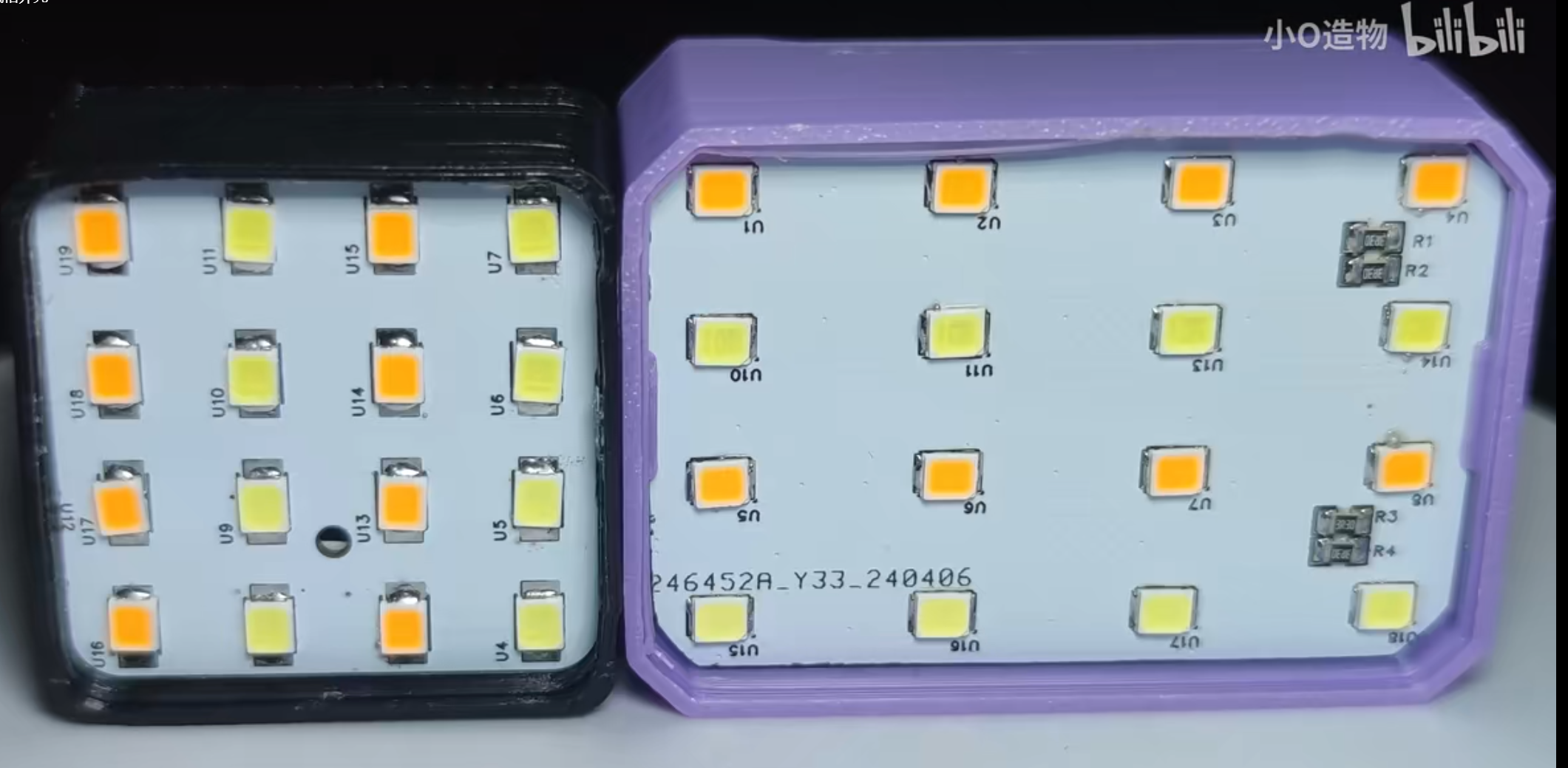
3. 16 High Color Rendering Index 2835 LEDs, Maximum Power 3W
4. 200mAh Lithium Battery, Approximately 20 Minutes of Battery Life at Maximum Power 5.
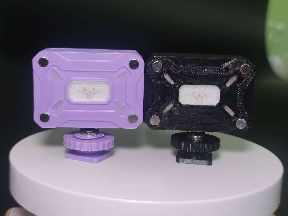
4 Strong Magnets and Softening Panel
6. Working Indicator and Charging Indicator 7. Supports Type-C Fast Charging 8. Can be Connected to Cold Shoe Mount + Magnetic Attachment or Cold Shoe Mount + 1/4"
Physical Display Description
1. Dimensions: 51.5*36.5*20mm
Pocket Light Upgrade (Compressed Version).mp4
PDF_Mecha-style Pocket Light - Open Source.zip
Altium_Mecha-style Pocket Light - Open Source.zip
PADS_Mecha-style Pocket Light - Open Source.zip
BOM_Mecha-style Pocket Light - Open Source.xlsx
91208
electronic
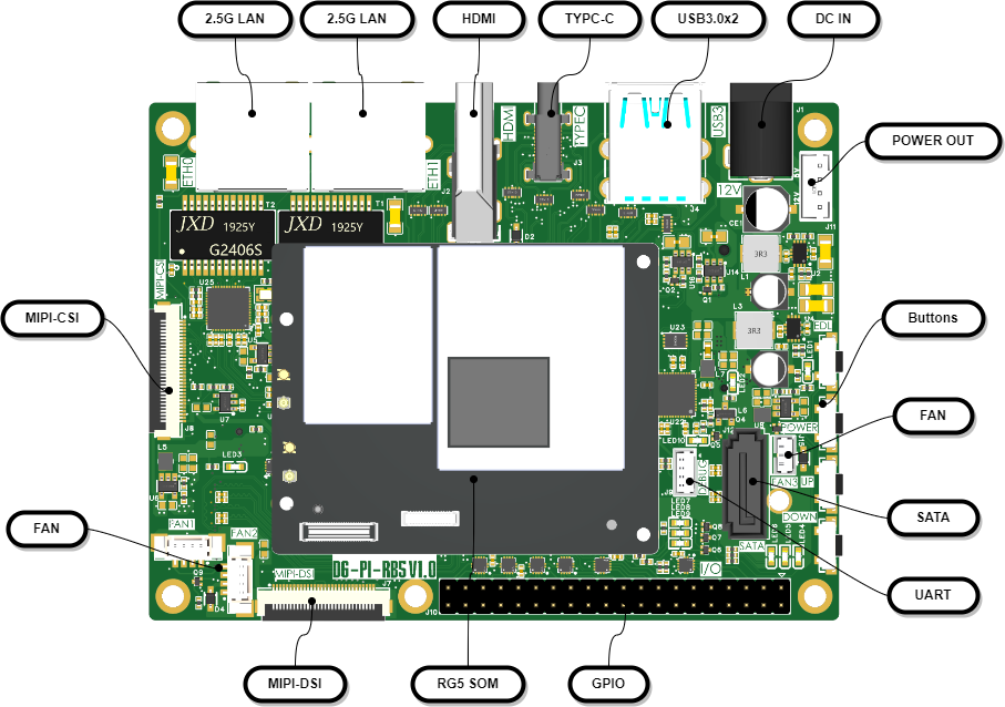
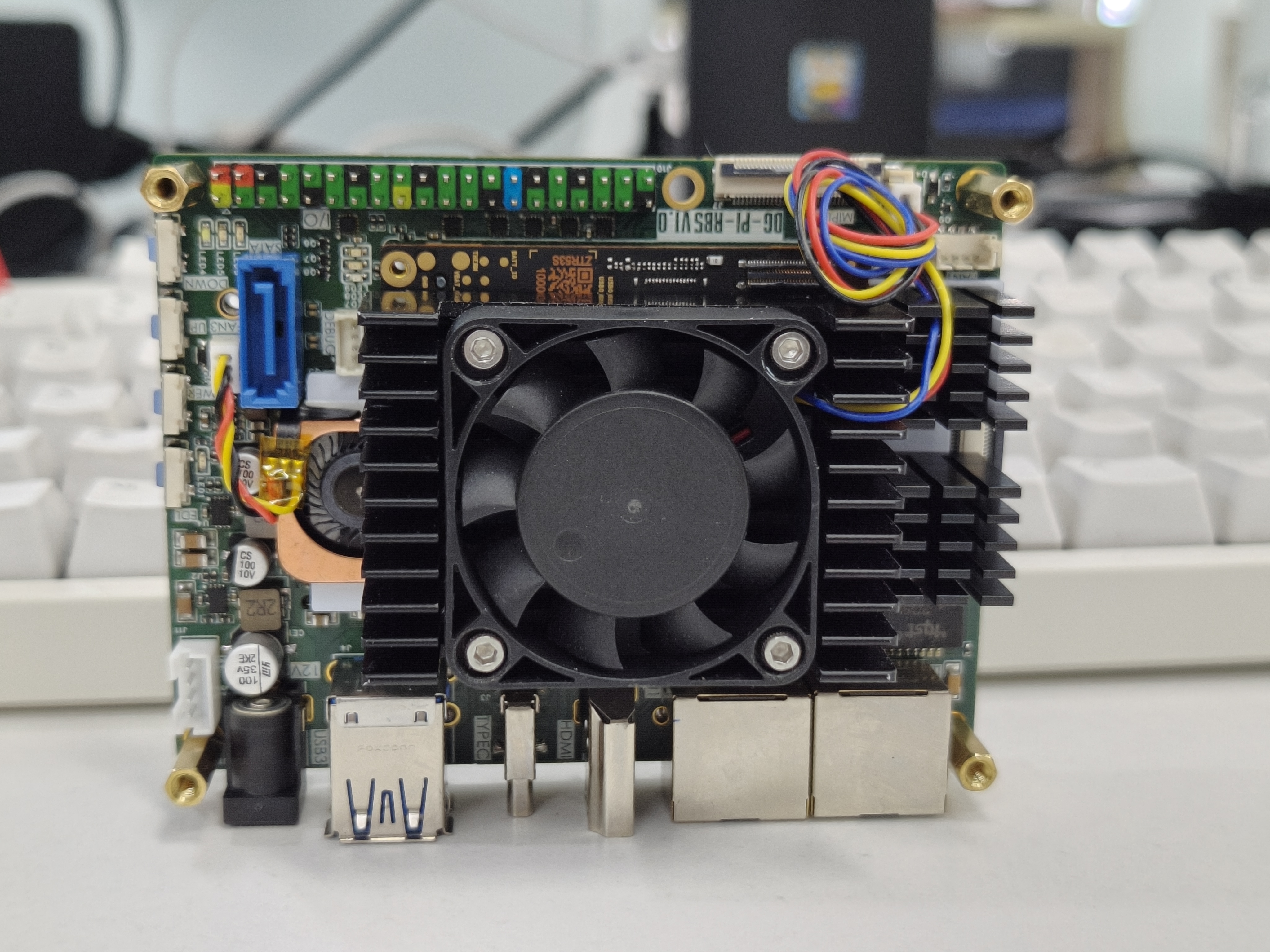
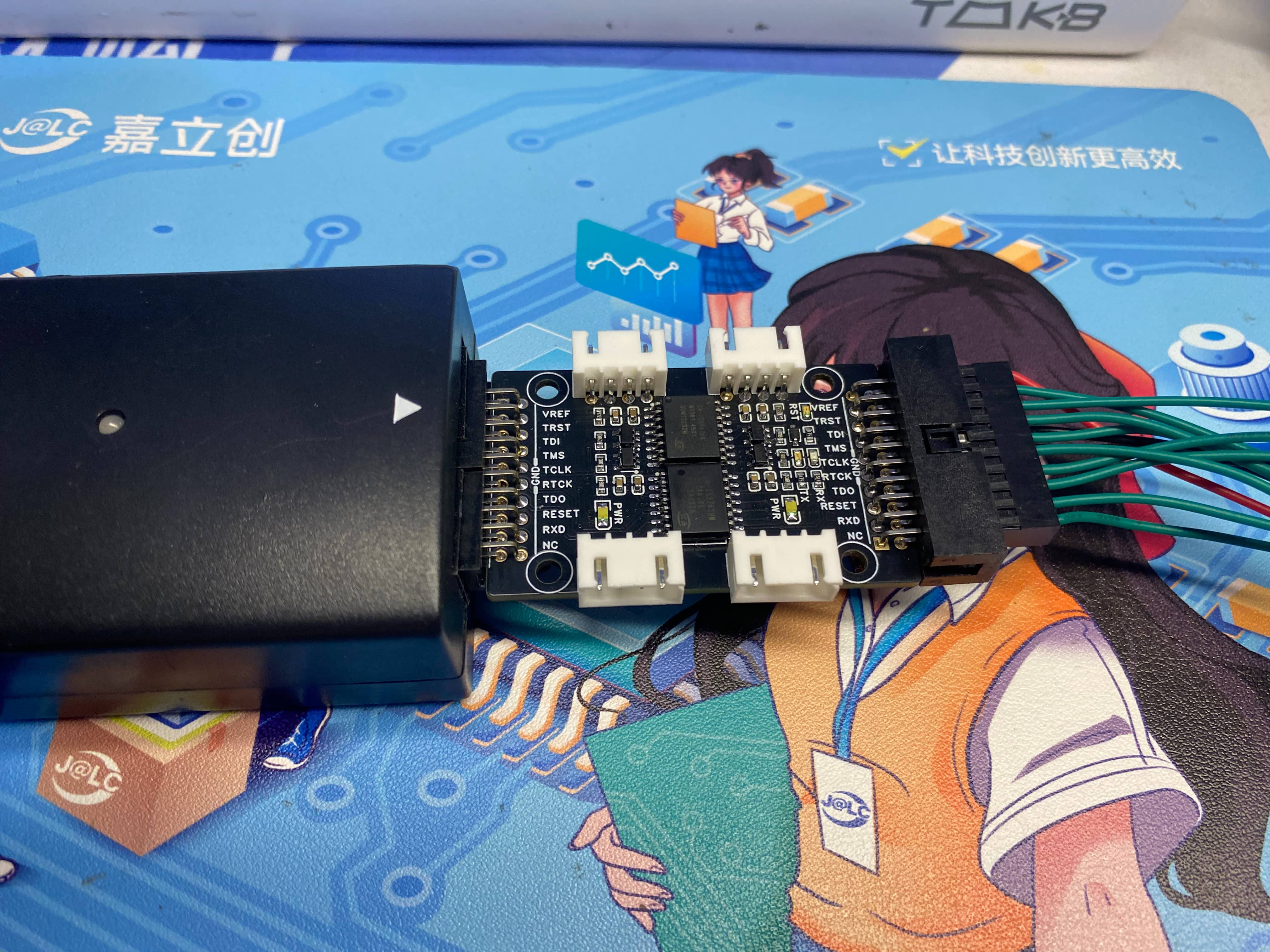
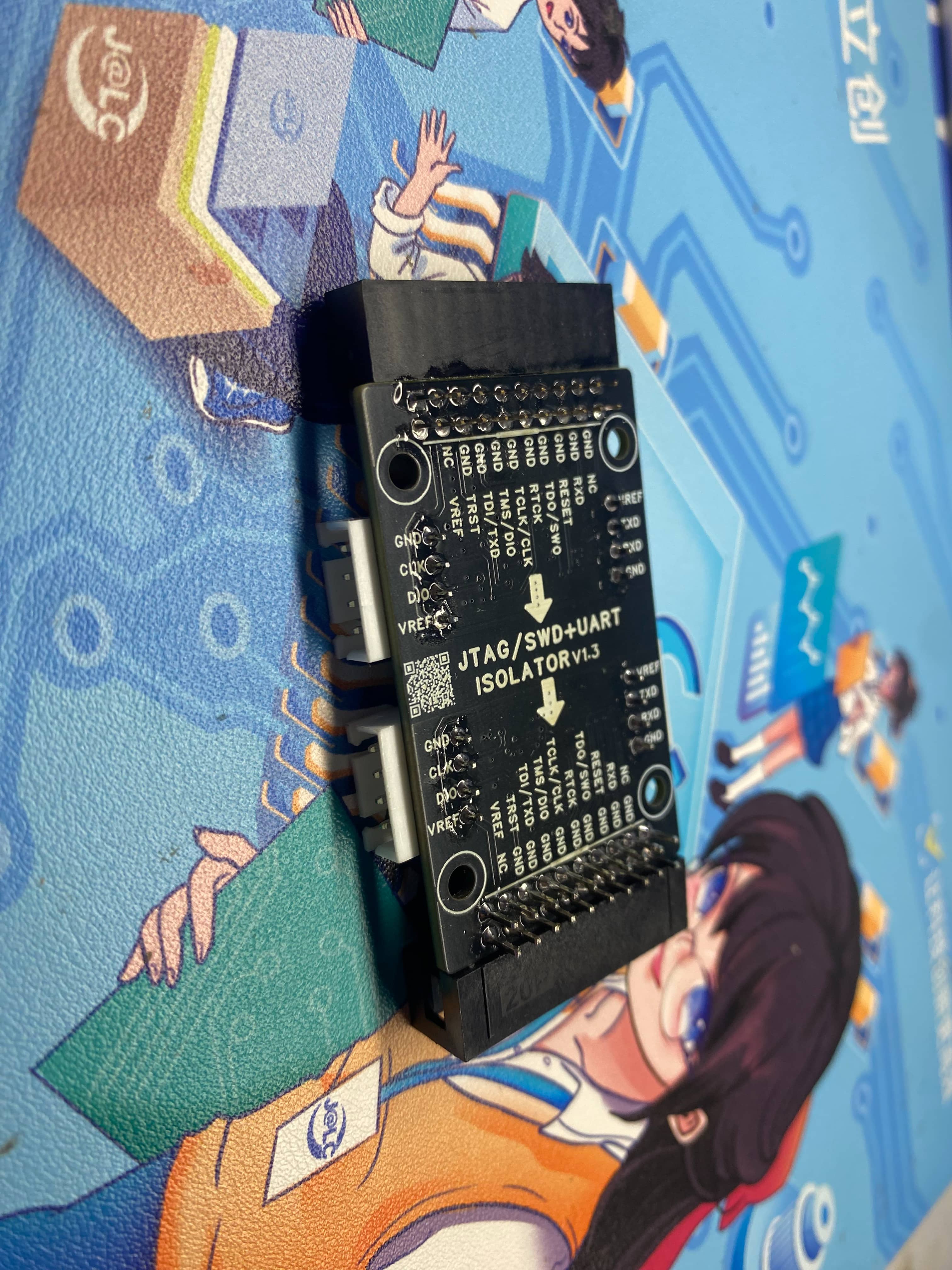
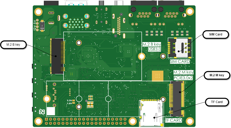 Hardware block diagram:

 [ Images of system interfaces are included
  .]
.] 


 ensure your version is V9 or higher,
 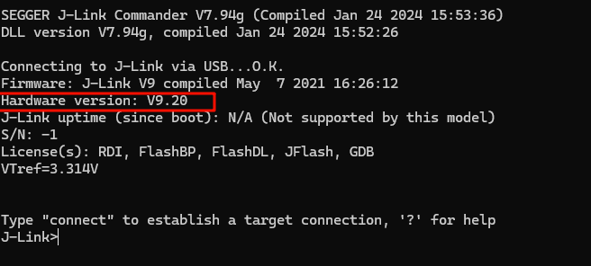 and enable the virtual serial port using the code
 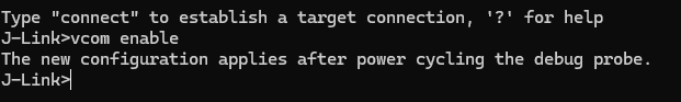 After restarting J-Link, you can use the virtual serial port. You can check the COM port number in My Computer - Device Manager.
 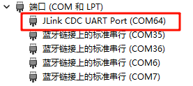 This enables data transmission and reception.
 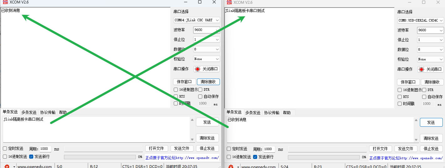 Due to my J-Link version issue, enabling high baud rates can easily cause serial port loss. My highest test baud rate was 25600. You can modify it according to your needs.
 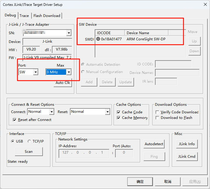 2. Using the D version of J-Link v9 in JTAG mode (for reference only):
 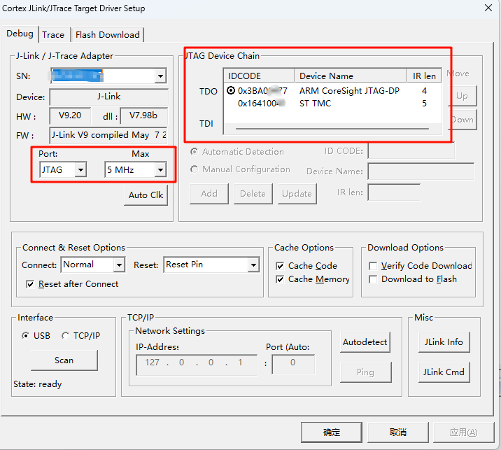 3. Using the Zhengdian Atom DAP, a stable download speed of 5MHz can be achieved (for reference only):
  Therefore, regarding the speed issue, you can modify the isolation chip or circuit scheme according to your own needs. This open source is for reference only.
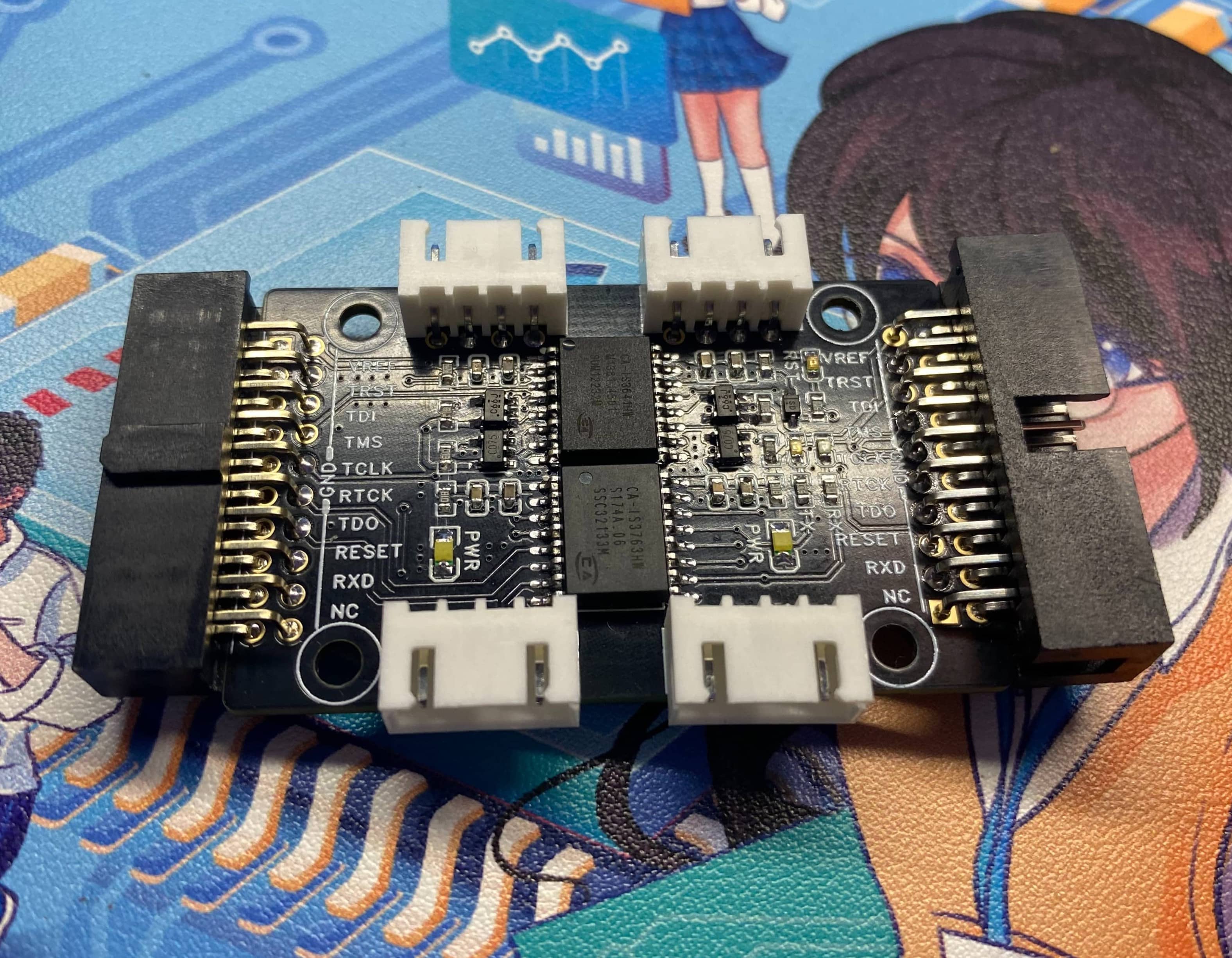
 Precautions
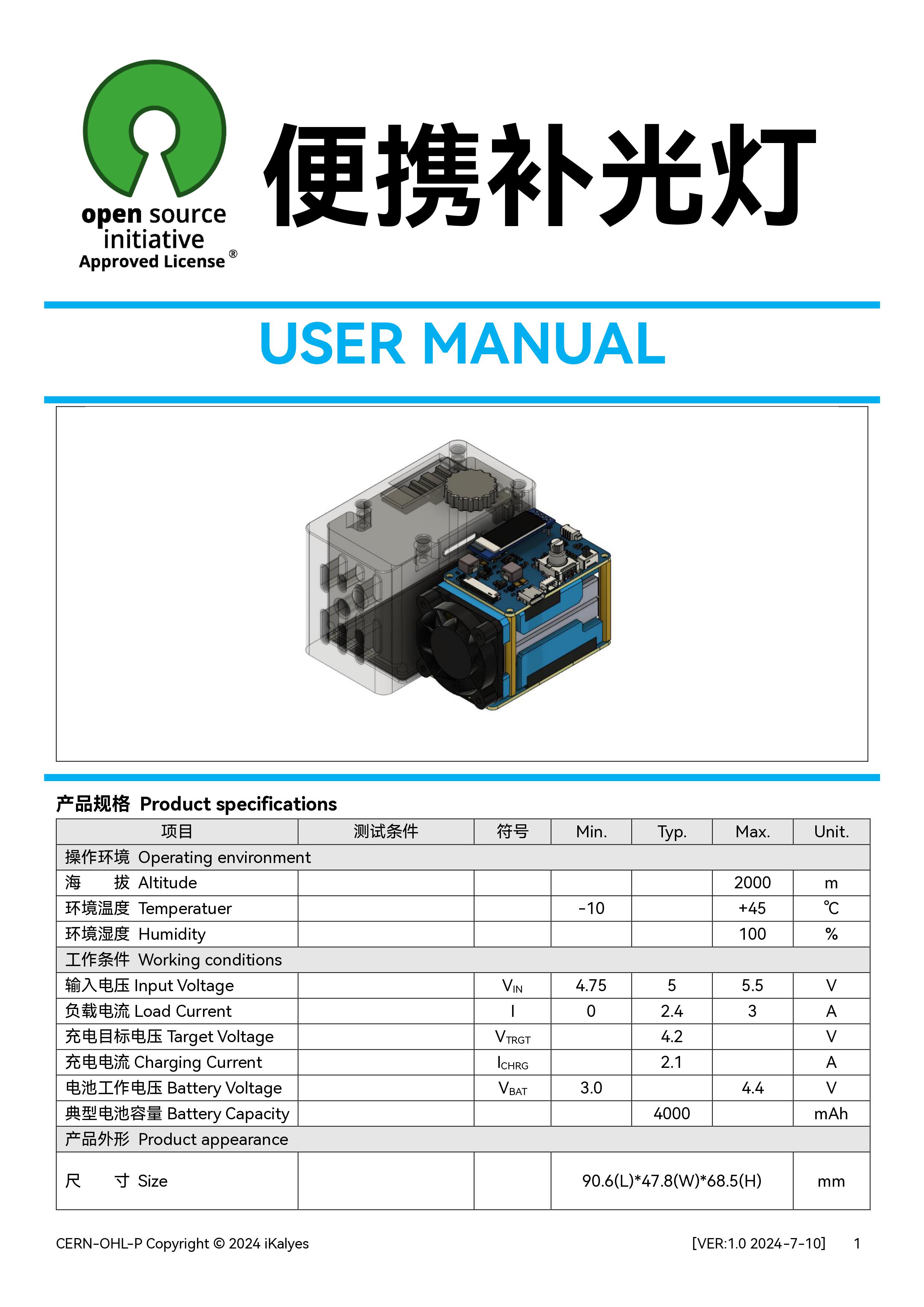
 Discussion group: 790715767.
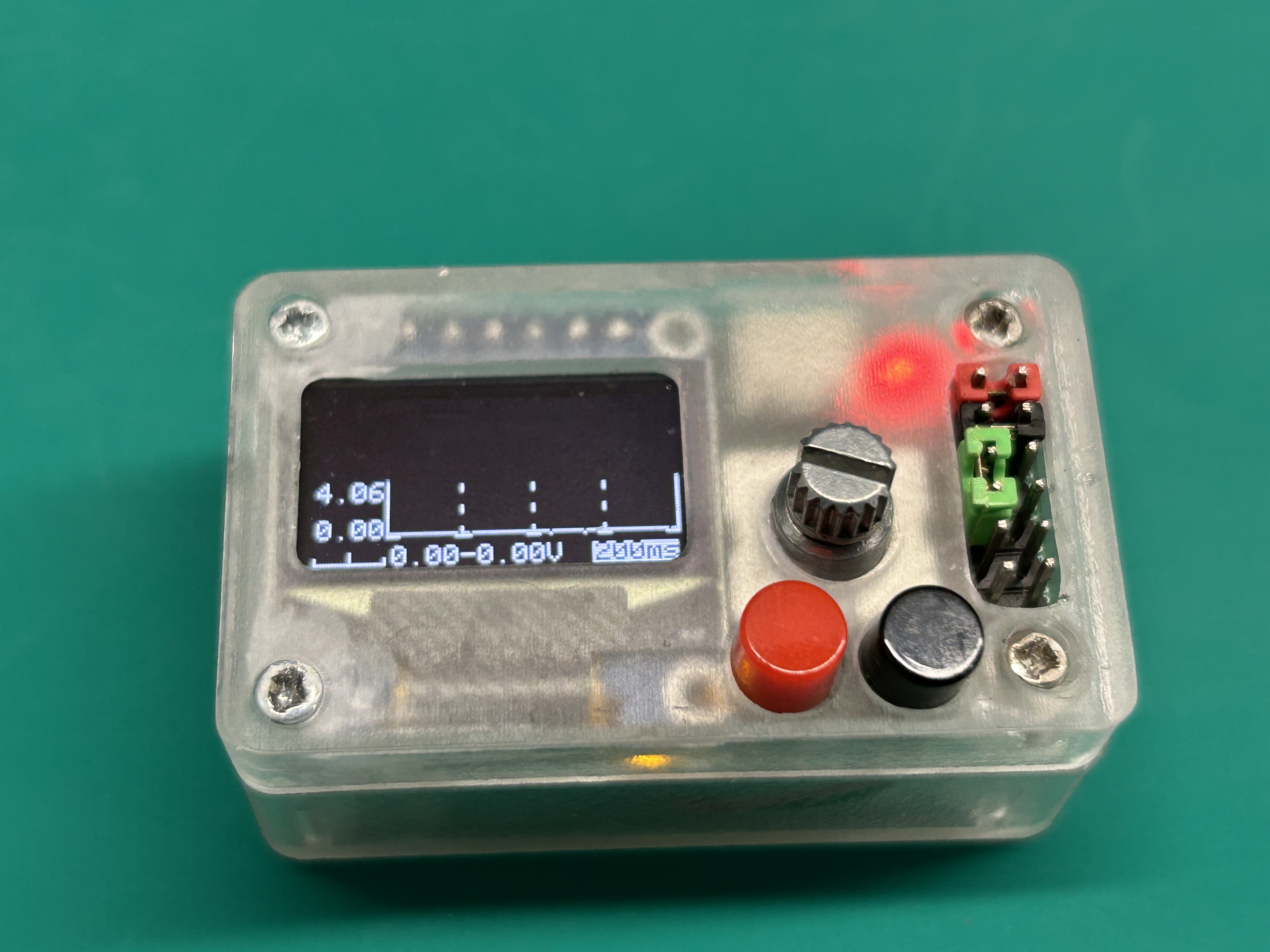


 Hardware Notes:
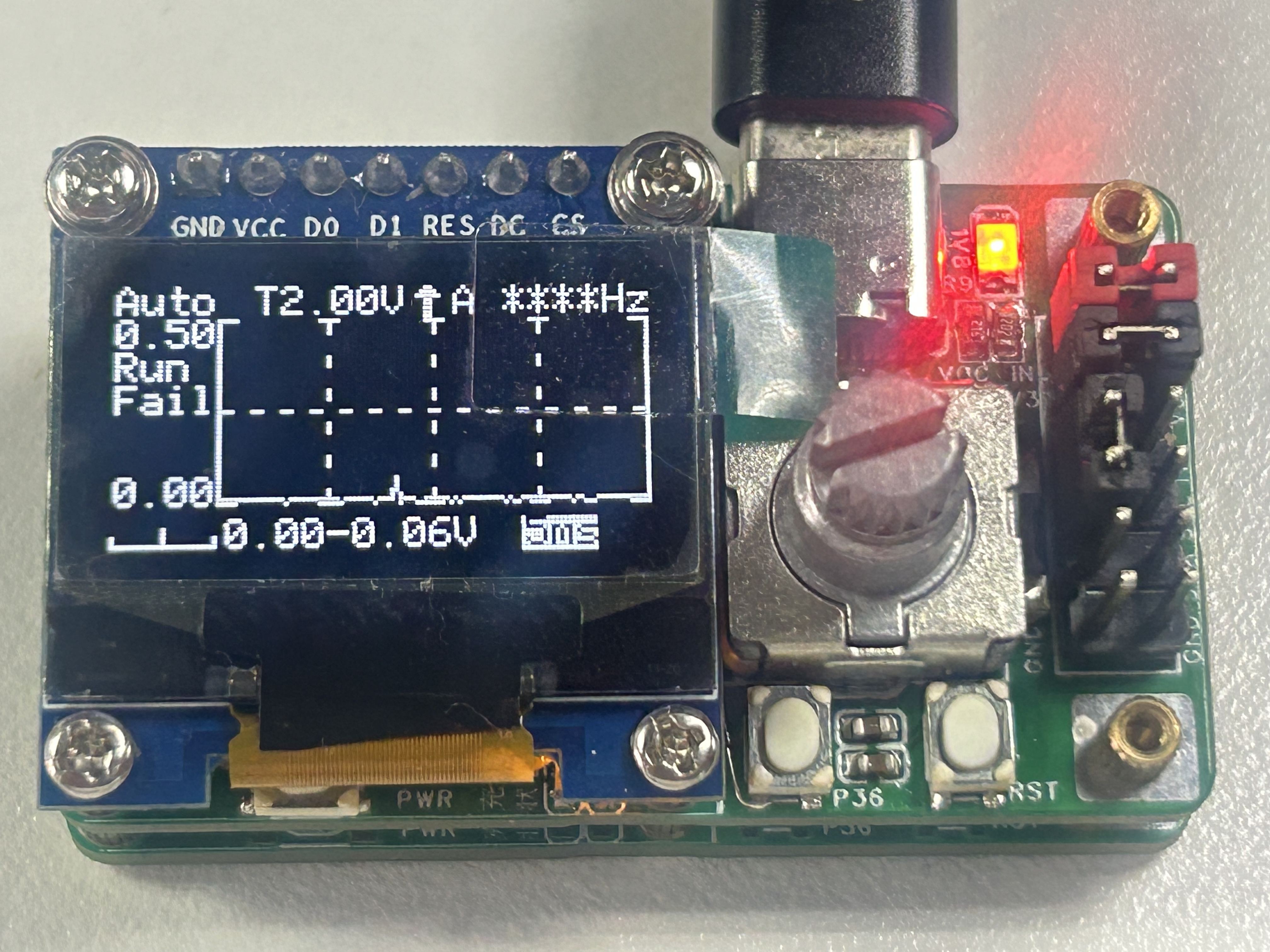
 Download Notes:
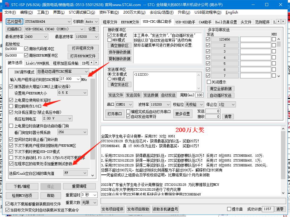


 京公网安备 11010802033920号

 150-Z1-318-00-106


