

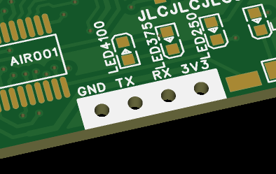
 It is recommended to solder it flat as shown in the image, using minimal solder. After programming, you can directly remove the header.
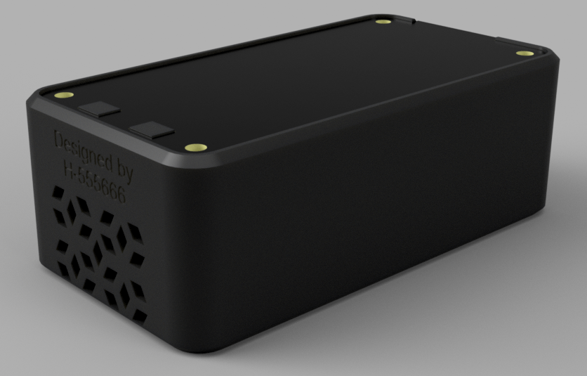
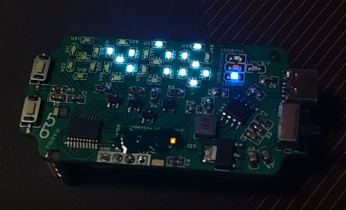
  data for IP4057 can be found in the documentation; pages 8-9 of the LED display description are copied here. This project is licensed under CC-BY-NC-SA 4.0. The code references the Adafruit_SGP30 library for obtaining SGP30 readings and calibration. The peripheral circuitry of IP5407 in the SGP30 schematic is modified from the project "5V Charging/Discharging Module IP5407". The SGP30 adapter board is inspired by @yanshimi's portable WIFI adapter board project . This is the first public release of this project; it is my original work. This project has not won any awards in other competitions. (This project has not participated in any other competitions) Project Progress 2024.4.2 and earlier: This page was created, and the schematic diagram, PCB design, and first version of the soldering code were completed and all ran normally. 2024.4.7: The outer shell is finished. Here are some renderings (awaiting prototyping). 2024.4.10: Updated physical images. 2024.6.20: Improved the description , added acrylic panel design principle & software description. The TVOC and CO2 concentration data measured by SGP30 are obtained through AIR001 and displayed on a four-digit PCB digital tube. After startup, the TVOC and CO2 concentration are checked once per second. If either value is too high, a warning light and the corresponding over-limit indicator light will light up (for example, if CO2 exceeds the limit, the CO2 indicator light and the warning light will flash simultaneously once per second). After startup, if the BOOT button is pressed briefly in the upper left corner of the board (U14), the current measurement value will be displayed for 5 seconds and the corresponding value indicator light will be lit. At this time, the value and display content will still be refreshed every second. If you press BOOT briefly again at the 2nd, 3rd, or 4th second, the display will switch to another value (e.g., after a short press of BOOT, the CO2 concentration measurement value will be displayed and the CO2 indicator light will illuminate; pressing it again after 2 seconds will switch to the TVOC concentration measurement value, at which point the TVOC indicator light will illuminate). After startup, if you press and hold BOOT for more than 4 seconds, the indicator light will remain constantly on and the measurement value will be refreshed. Pressing it briefly again will turn off the constant illumination. The SGP30 sensor needs to warm up each time it starts (about half a minute), so a startup animation has been made. After startup, placing the sensor in a well-ventilated area for a while will provide more accurate readings. When using battery power, connecting an external power source will not cause the main controller to restart (but disconnecting the external power source will most likely cause a restart, due to IP4057 characteristics). Physical demonstration: First generation - standby mode (the power indicator light was too bright, so a lot of solder resist was applied to block the light). First generation - displaying CO2 concentration (476ppm). Notes: Try to buy IP4057 chips from reputable sources. The chips I initially bought on Taobao stopped working after a while; replacing them with those from LCSC Mall fixed the problem. Acrylic panels are slightly expensive; you can selectively order them or integrate them into other large boards, or use a PCB instead (the effect will be slightly worse). Other source code is in the attachment; please use Arduino to program it yourself.


All reference designs on this site are sourced from major semiconductor manufacturers or collected online for learning and research. The copyright belongs to the semiconductor manufacturer or the original author. If you believe that the reference design of this site infringes upon your relevant rights and interests, please send us a rights notice. As a neutral platform service provider, we will take measures to delete the relevant content in accordance with relevant laws after receiving the relevant notice from the rights holder. Please send relevant notifications to email: bbs_service@eeworld.com.cn.
It is your responsibility to test the circuit yourself and determine its suitability for you. EEWorld will not be liable for direct, indirect, special, incidental, consequential or punitive damages arising from any cause or anything connected to any reference design used.
Supported by EEWorld Datasheet
EEWorld
subscription
account

EEWorld
service
account

Automotive
development
community

Robot
development
community

About Us Customer Service Contact Information Datasheet Sitemap LatestNews


Room 1530, 15th Floor, Building B,
No.18 Zhongguancun Street,
Haidian District,
Beijing, Postal Code: 100190
China
Telephone: 008610 8235 0740
 京公网安备 11010802033920号

 CZMA22V


