What should you pay attention to when using an X99 motherboard at home? I think you must strengthen the heat dissipation of the power supply MOSFETs. A motherboard around 200 yuan is really too expensive to burn out.
See the results here: https://www.bilibili.com/video/BV1kteDexEFk/
First,
let's build a PWM speed control system for a cooling fan around an STC8H8K64U microcontroller that supports 5V power. It's specifically designed for inexpensive 12V 3-pin cooling fans because I can't afford 4-pin fans with temperature control. Two connectors are dedicated to low-current 3cm/4cm cooling fans, and two connectors allow for slightly higher-power case fans. High-powered fans are out of the question.

This project supports manual speed control for both fans, or automatic speed adjustment based on the NTC sensor. It has already been tested on a computer, using the large 4-pin connector of the power supply to drive two 4cm fans, and they spin. The noise is significantly reduced when the heatsink is at low temperatures compared to full speed. Before powering on, you can set the mode to manual or automatic using jumpers. The digital tube can display the manual mode setting or the temperature of the MOS heatsink and fan speed in automatic mode.
Temperature values have a certain margin of error and are for principle verification only. For accurate results, please further refine the program according to the datasheet.
II. Precautions:
The PCB has several bugs, but these are minor and do not affect use if they can be resolved with jumper wires or simple adjustments. After repair, it has been verified to be working correctly; please see the Bilibili video.
Due to my computer system issues, USB programming was not possible; therefore, an external header was used with an automatic programmer to program via serial port.
The diode at the original USB interface must be removed.
The fan pin definitions on the front of the PCB (chip side) are reversed; please delete them during prototyping.
The silkscreen markings for the BOOT and RESET pins appear to be reversed, but these pins are not needed with an automatic programmer.
Temperature measurement results are for principle verification only; the least squares fitting results have a significant error.
Other bugs need further investigation.
I've been too busy lately to do a second prototyping. During use, please note:
Select automatic mode (unconnected) or manual mode (connect jumper cap) via H2.
Please connect an NTC thermistor to the RTEMP port to measure the temperature of the motherboard MOSFET heatsink.
An external button can be connected to the H4 interface for future manual control. This feature is yet to be added.
Currently, it supports dual-fan temperature-controlled cooling (two 4cm fans). The two fan connectors at the bottom are temporarily reserved for future use in chassis temperature-controlled cooling.
The PWM repetition frequency of the fans may need to be adjusted based on the actual fans. The microcontroller's main frequency is configured at 24MHz.
If possible, an automatic programmer can be purchased to eliminate the need for manual power-on/off during programming.
Why isn't the PWM code for the two fans below written? Because there's no money to buy a chassis at the moment...

daima.zip
STC8H Thermal Design JLCPCB Platform Version.mp4
PDF_x99's Friends: Cooling Fan Controller.zip
Altium_x99 Friends: Cooling Fan Controller.zip
PADS_x99 Friends: Cooling Fan Controller.zip
BOM_x99's Friends: Cooling Fan Controller.xlsx
93556
STC8051U core board
Primarily used for verification and testing of the STC8051U microcontroller.
The task requires
verification and testing of the STC8051U microcontroller.
The analysis of the task
involves designing a core board for verification and testing based on the official datasheet .
The schematic design describes
the core board, which mainly consists of an STC8051U minimum system and a CH340N USB-to-TTL chip. This allows for both automatic downloading and USB-to-TTL serial communication; it is also compatible with the traditional STC89C52RC microcontroller.
The PCB design is
for a low-speed board and can be drawn using the default rules of JLCPCB EDA software; no special requirements are specified.
The
software is ported and modified from code generated by STC-ISP software; see the attachment for details.
A physical demonstration is shown
in the following video .
f9c14adaf2940925ebdc2bf5d4a331d0.mp4
STC8051U test code.zip
PDF_STC8051U core board.zip
Altium_STC8051U core board.zip
PADS_STC8051U core board.zip
BOM_STC8051U Core Board.xlsx
93558
FM350-GL 5G Module to USB Adapter Board [USB 3.0 Verified]
FM350-GL 5G module to USB adapter board, supports USB 2.0/USB 3.0, single nano-SIM.
USB 3.0 only supports one side. Inserting it correctly activates USB 3.0, while inserting it incorrectly activates USB 2.0. The LED color changes depending on the orientation (pinkish-purple for USB 3, yellow for USB 2)
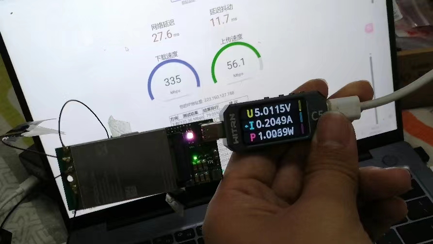
. Make sure you insert the correct LED when wiring the circuit board; the first draft is unusable.
PDF_FM350-GL 5G Module to USB Baseboard [USB 3.0 Verified].zip
Altium_FM350-GL 5G Module to USB Baseboard [USB 3.0 Verified].zip
PADS_FM350-GL 5G Module to USB Baseboard [USB 3.0 Verified].zip
BOM_FM350-GL 5G Module to USB Backplane [USB 3.0 Verified].xlsx
93559
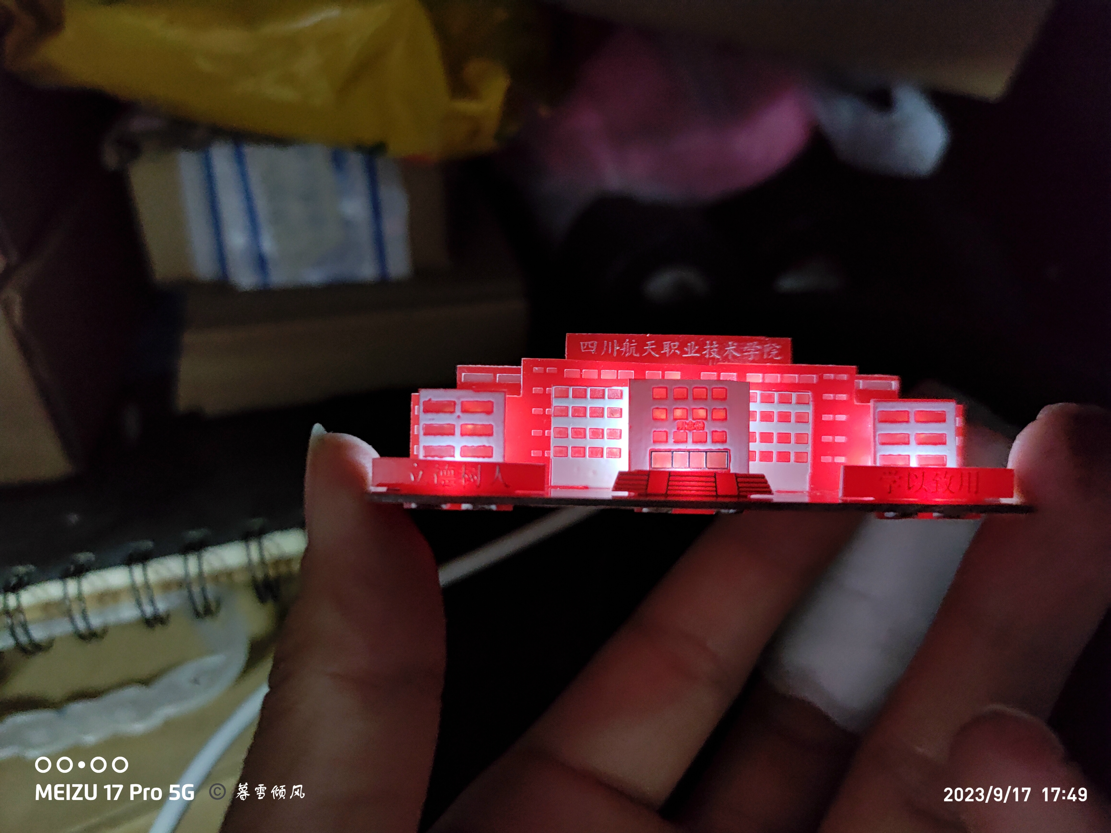
3D Illuminated Puzzle of Sichuan Aerospace Vocational and Technical College
3D Illuminated Puzzle of Sichuan Aerospace Vocational and Technical College
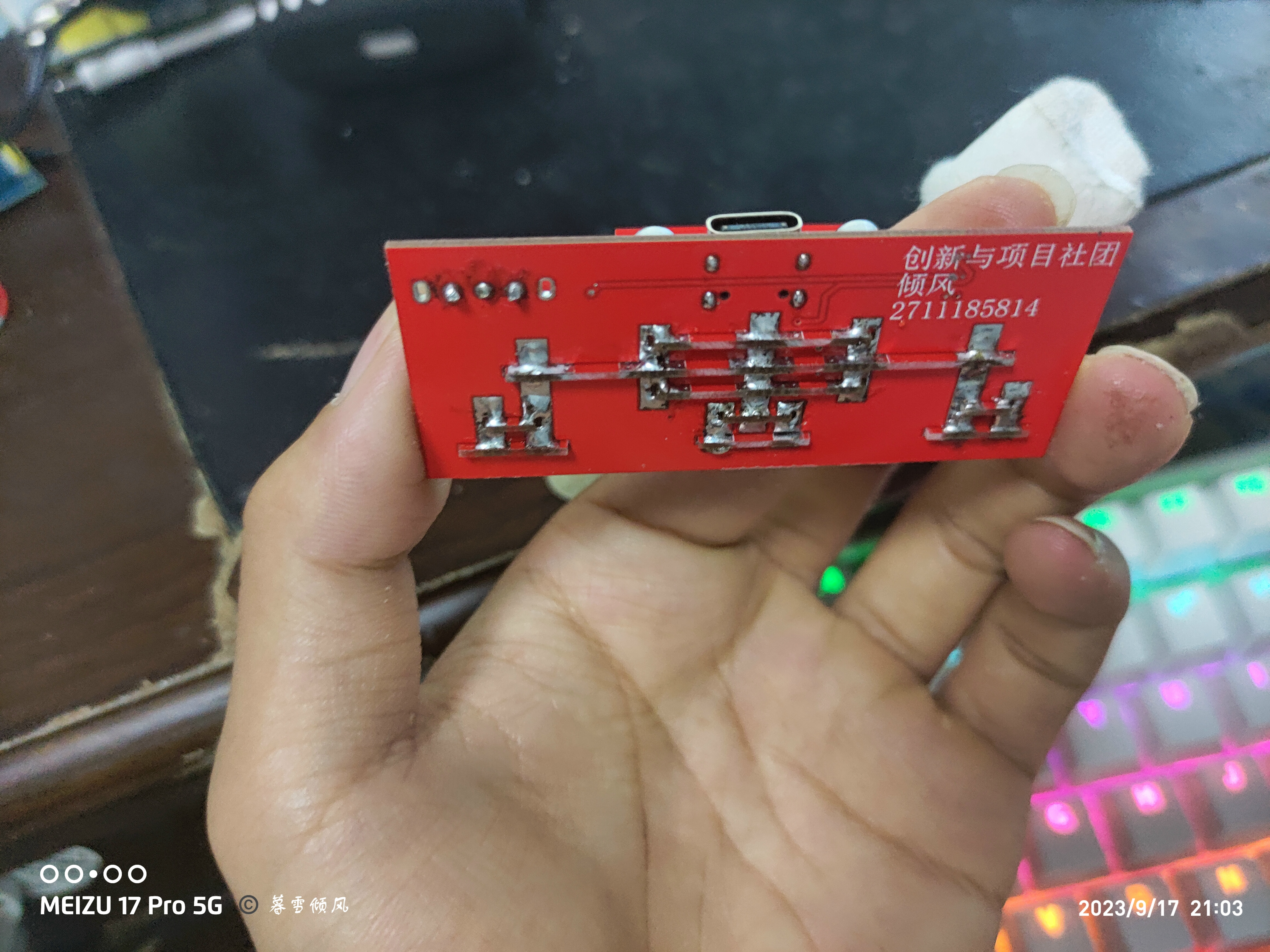
After receiving the 3D illuminated jigsaw puzzle from Sichuan Aerospace Vocational and Technical College, it needs to be cut.
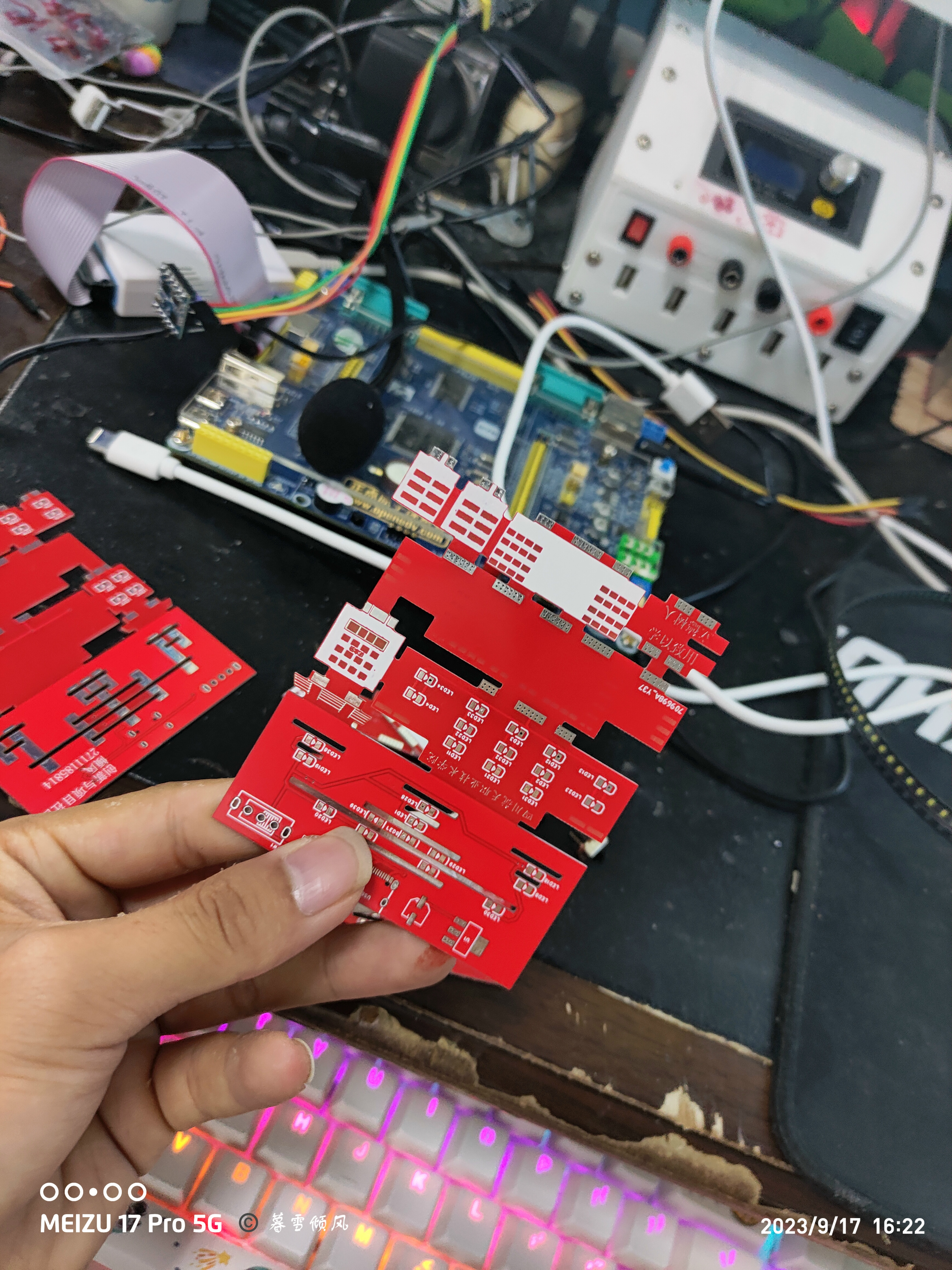
Each part

has solder pads that need to be soldered.
I
used a self-made heating table and solder paste for surface mount soldering. Pay attention to the positive and negative directions of the LEDs during soldering. Here's
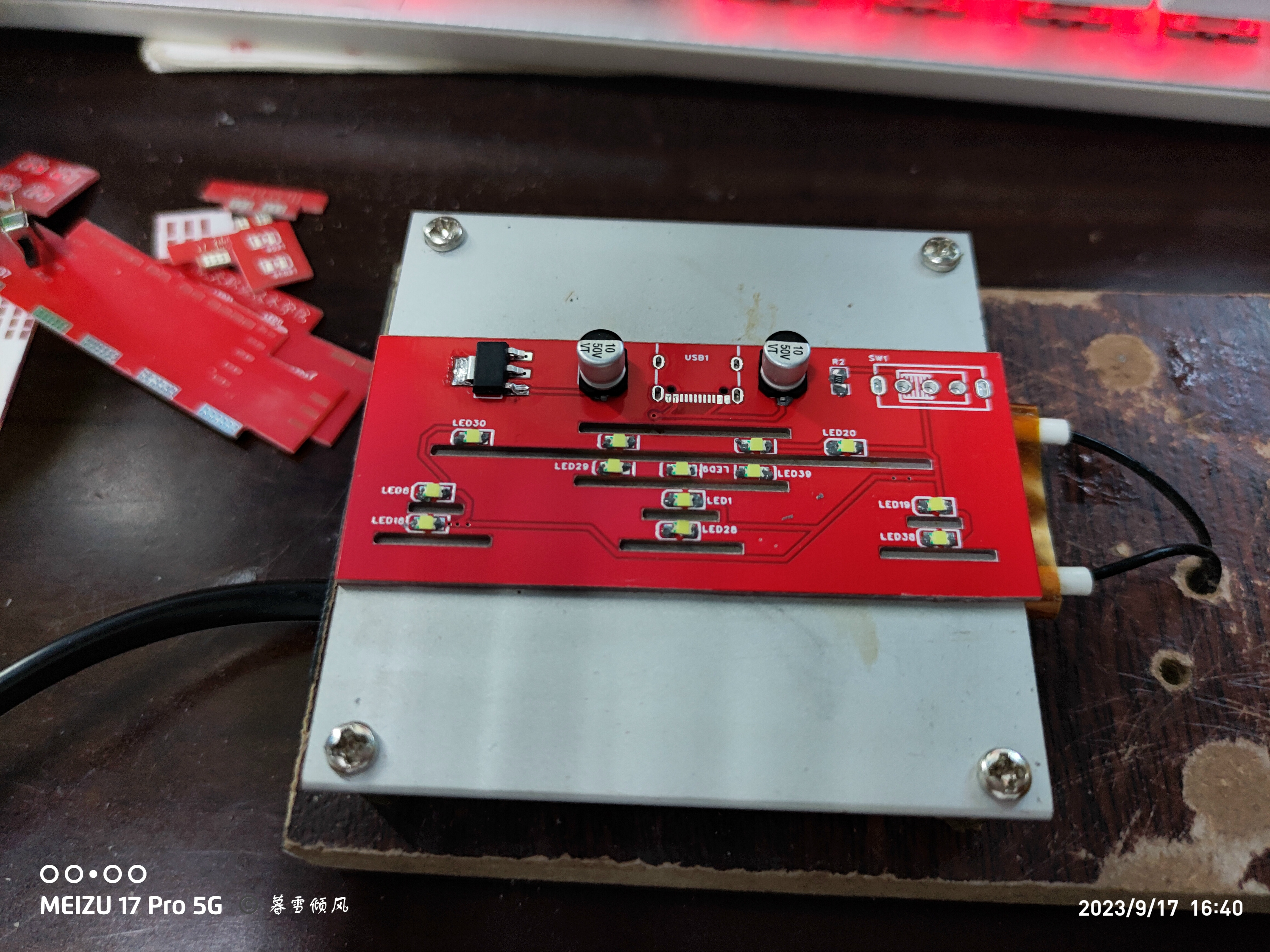
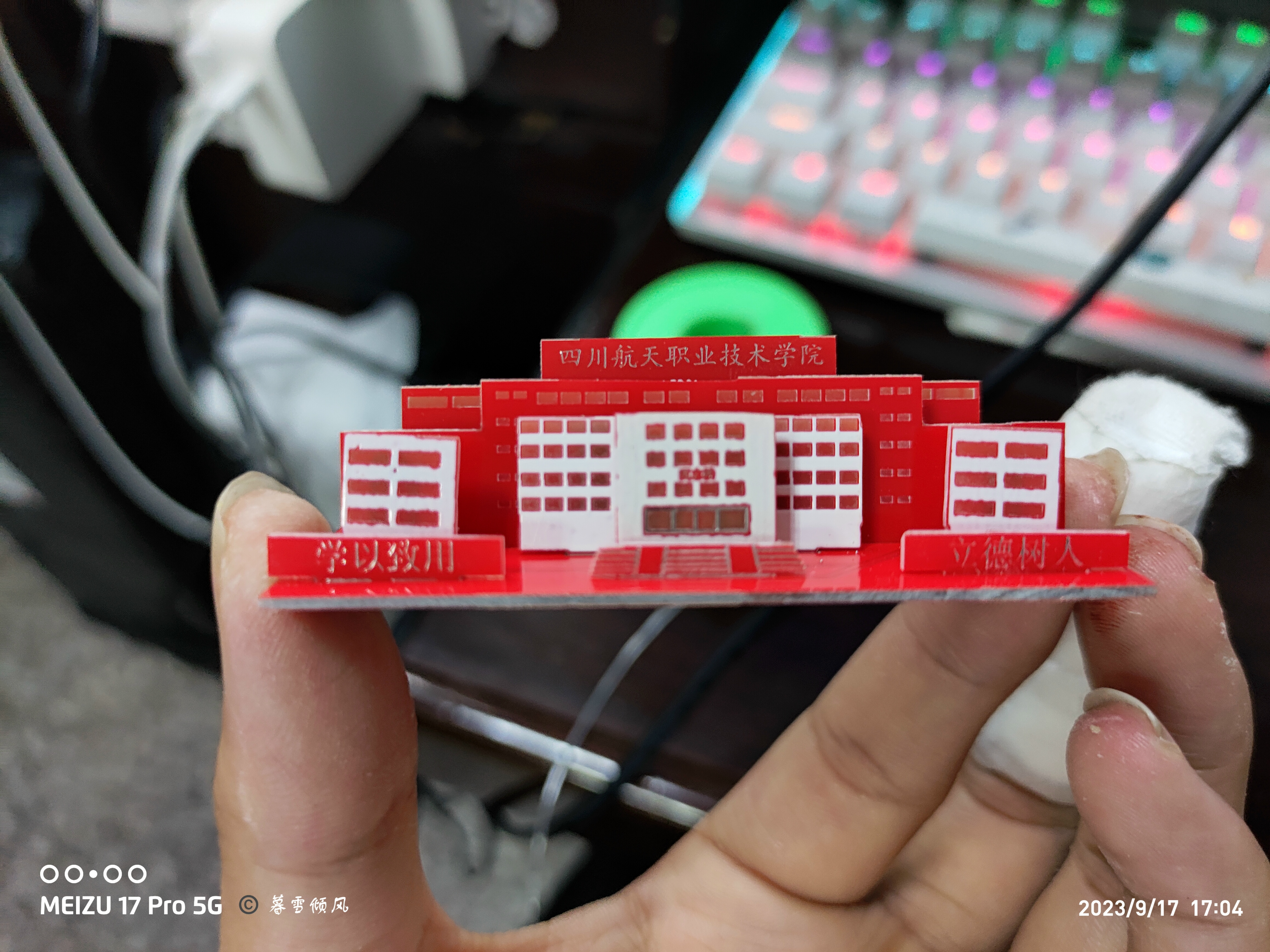
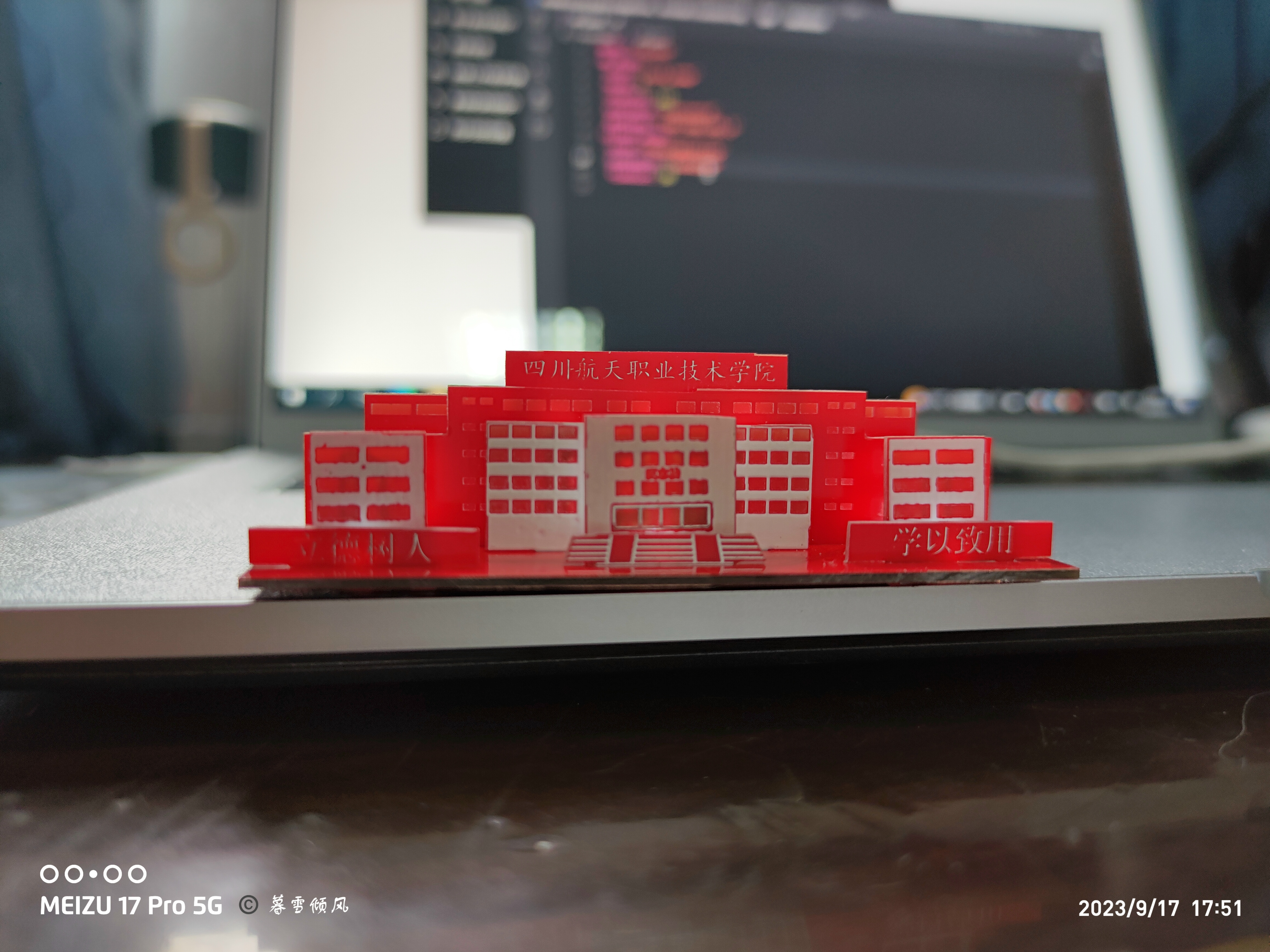
a preview of the finished product:
this is the top,
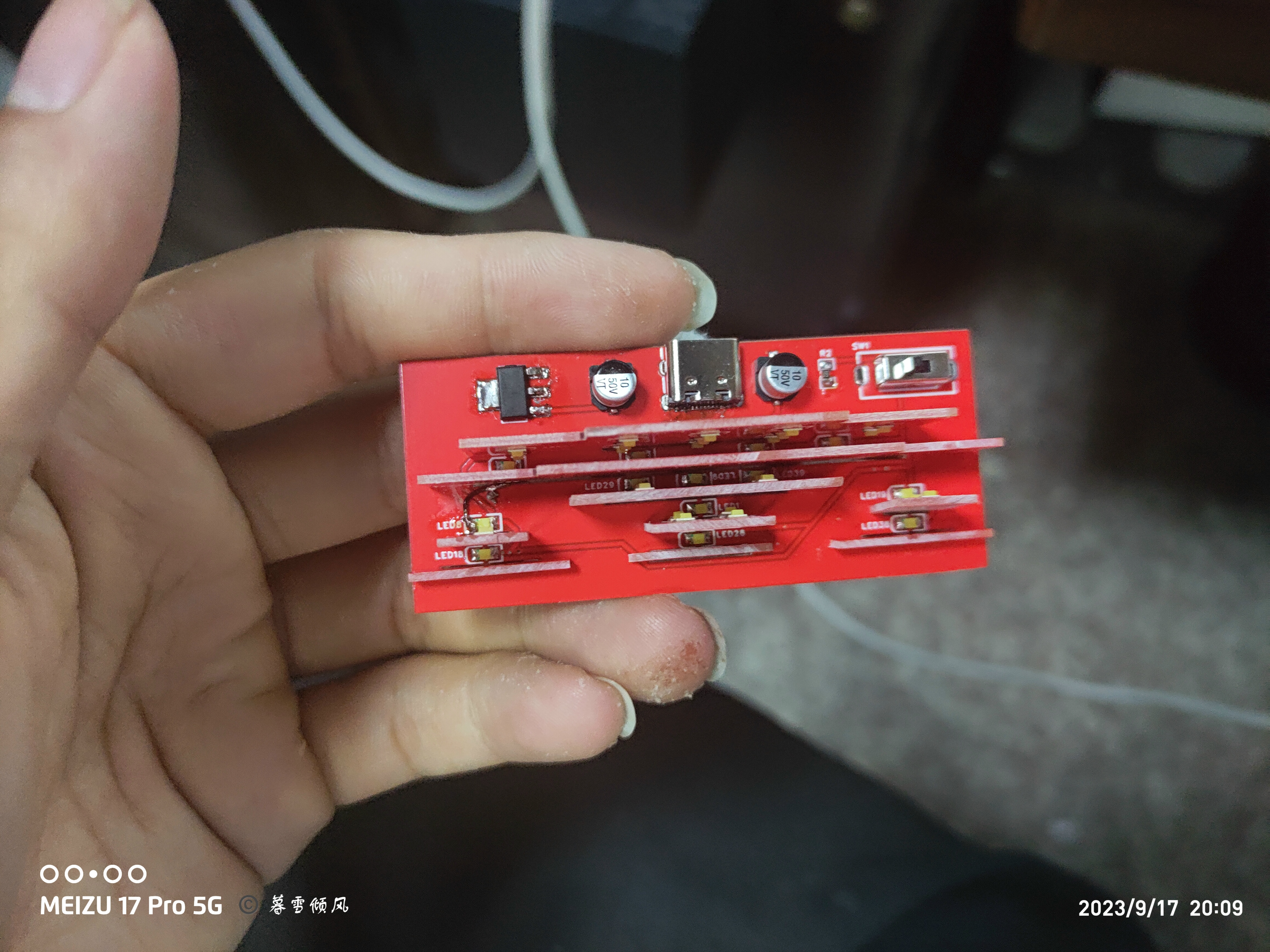
this is the bottom, note the order of the different board layers.
Finally, here's the overall view.

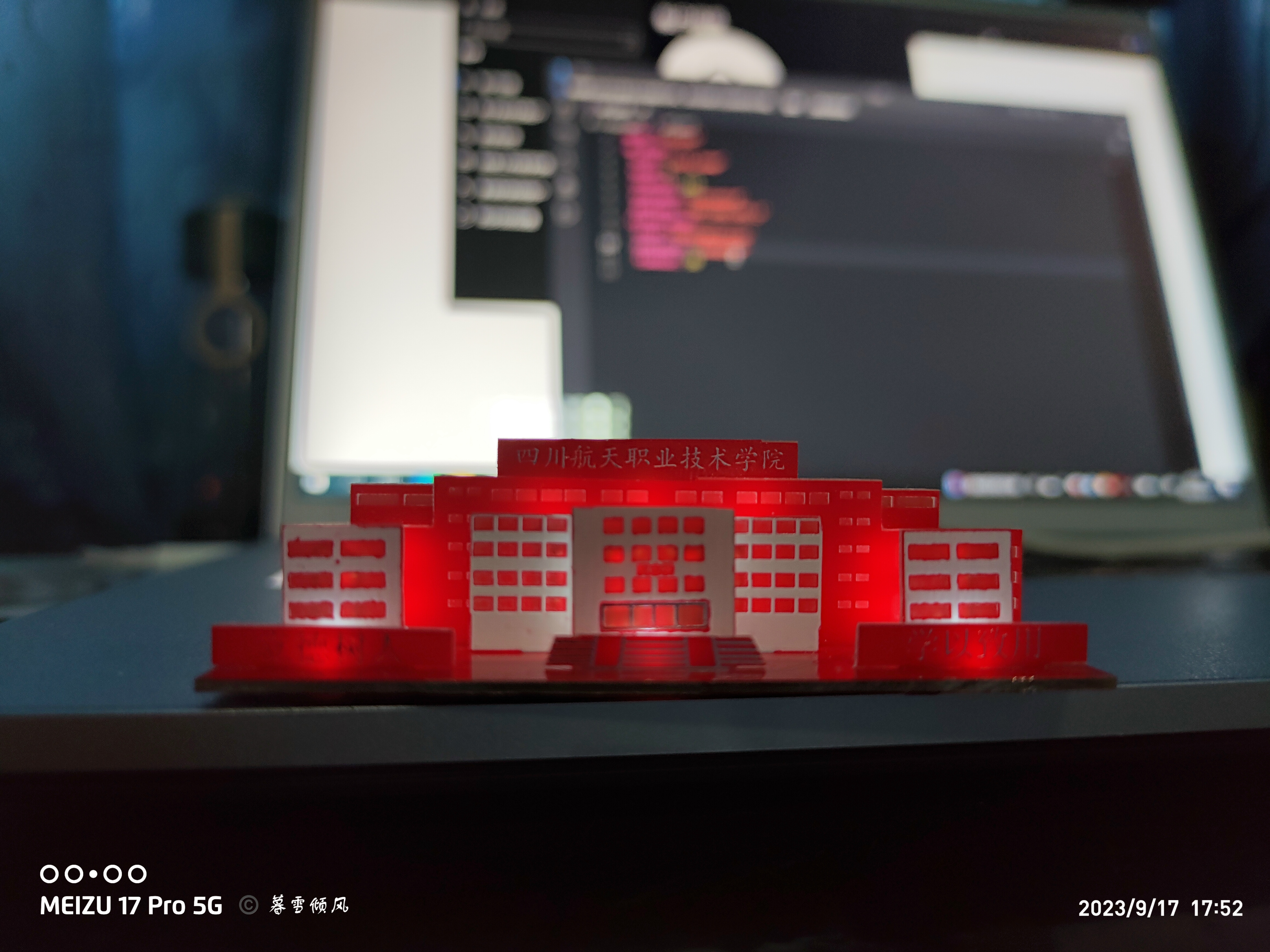
Below is the effect after turning on the lights.
PDF_Sichuan Aerospace Vocational and Technical College 3D Illuminated Puzzle.zip
Altium_Sichuan Aerospace Vocational and Technical College 3D Illuminated Puzzle.zip
PADS_Sichuan Aerospace Vocational and Technical College 3D Illuminated Puzzle.zip
BOM_Sichuan Aerospace Vocational and Technical College 3D Illuminated Puzzle.xlsx
93560
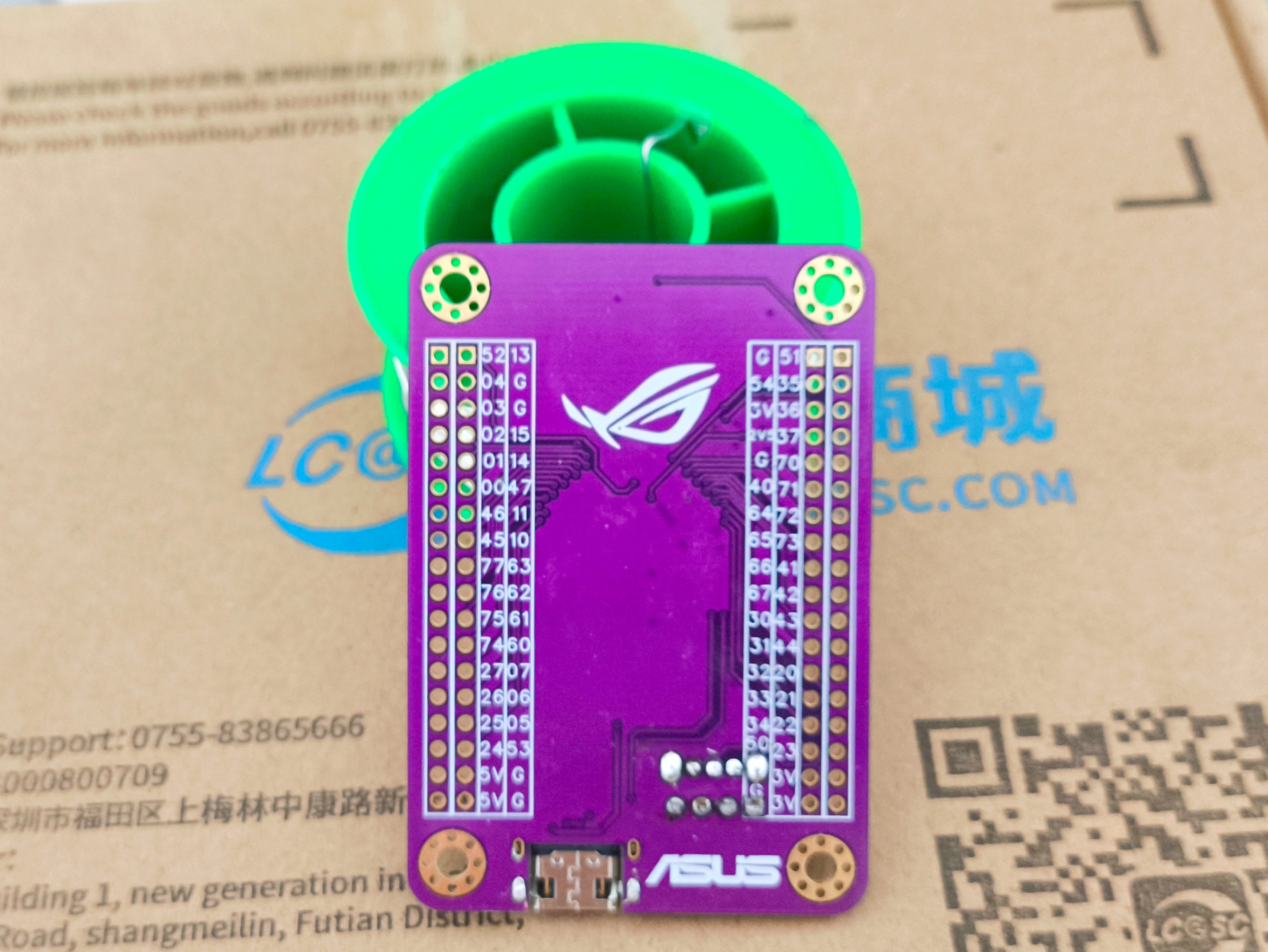
STC8H8K64U_ROG Development Board
A mini development board based on the STC8H8K64U, supporting USB download.
This development board is based on the STC8H8K64U and features
59 I/O ports,
onboard LED indicators
, support for external crystal oscillators
, and direct USB program download.
Its distinctive ROG paint job adds a touch of prestige.

main.c
STC8A8K64D4.H
progect.hex
bb383664a23bbc12da2b5cc1024076d8.mp4
PDF_STC8H8K64U_ROG Development Board.zip
Altium_STC8H8K64U_ROG development board.zip
PADS_STC8H8K64U_ROG development board.zip
BOM_STC8H8K64U_ROG Development Board.xlsx
93561
Mini CH343P Serial to USB Module
This module was designed to solve the problem of conventional USB-to-serial modules being unable to connect to Type-C ports.
USB-to-serial modules purchased online typically only connect to a computer via USB, often requiring a USB extension cable. To avoid this, a serial module with a direct Type-C cable connection was designed. This allows for most connection functions during debugging with just one cable (primarily because USB extension cables are expensive and difficult to use)
.

The module uses a CH343P chip to convert the USB port to **3.3V TTL level** (if 5V TTL is required, please modify the circuit accordingly). The board provides both 5V and 3.3V power supplies. The 3.3V power is provided by the RT9013, and the **maximum output is recommended not to exceed 400mA** (the RT9013 is rated at 500mA, but considering heat generation, such a high current is not recommended). **Do not use in high-power applications such as motors.**
The CH343P uses a QFN16 package, and all capacitors on the board are 0603 packages. Neither of these packages is beginner-friendly; **it is recommended to use a heated platform and hot air gun for soldering**. The CH343P also has pads on the bottom, but the bottom GND pad is mainly for heat dissipation and soldering is not mandatory. If soldering skills are limited, **prioritize ensuring stable connections of the pins around the perimeter**.
![Screenshot 2024-07-25 092121.png]

All project files come from JLCPCB's SMT basic and extended libraries, enabling SMT placement. **The BOM is for reference only**.
PDF_Mini CH343P Serial to USB Module.zip
Altium Mini CH343P Serial to USB Module.zip
PADS_Mini CH343P Serial to USB Module.zip
BOM_Mini CH343P Serial to USB Module.xlsx
93562
EastMartrix Pixel Clock Light Panel
This is a modification of the EastMartrix pixel clock light panel based on the open-source code from Bilibili's Da Congming.
The EastMartrix pixel clock light board, which originally required 4x64, can be implemented by changing it to 2x128.
PDF_EastMartrix Pixel Clock Light Board.zip
Altium_EastMartrix Pixel Clock Light Board.zip
PADS_EastMartrix Pixel Clock Light Board.zip
BOM_EastMartrix Pixel Clock Light Board.xlsx
93564
A linear CCD camera-guided intelligent vehicle controlled by an STC32G128K microcontroller.
This intelligent line-following vehicle, based on the STC32G128K microcontroller, uses a CCD camera as a data collection sensor and gyroscopes and other attitude sensors for auxiliary operation. It controls the vehicle's line-following by controlling the PWM output of a DC motor.
This project aims to design an intelligent car capable of autonomous line following. By integrating multiple advanced sensor technologies and precise control algorithms, it achieves efficient and stable line following functionality.
The intelligent line-following car uses an STC32G128K microcontroller as its core control unit, fully leveraging its powerful computing capabilities and rich interface resources. A CCD camera is used as a data collection sensor, capable of capturing ground trajectory information in real time and accurately. The CCD camera sensor features high resolution and fast response, providing the car with clear and reliable visual input.
To further improve the car's operational stability and attitude control accuracy, attitude sensors such as gyroscopes are also introduced for auxiliary operation. The gyroscope can sense changes in the car's tilt angle and angular velocity in real time, providing the microcontroller with precise attitude data, thereby enabling more accurate dynamic adjustments.
In terms of power drive, the motor's speed and torque are precisely adjusted by controlling the PWM output of the DC motor. The application of PWM technology makes motor control smoother and more efficient, allowing for flexible adjustments to the car's speed and steering according to different road conditions and line-following requirements.
After the car starts, the CCD camera sensor continuously scans the ground trajectory, transmitting the collected data to the microcontroller. The microcontroller quickly processes and analyzes this data, combining it with data from attitude sensors such as gyroscopes to calculate the optimal motor control strategy. Then, it outputs corresponding PWM signals to control the rotation of the DC motor, enabling the car to travel accurately and stably along a predetermined trajectory.
WeChat_20240723234020.mp4
WeChat_20240724141936.mp4
PDF_Intelligent Car for Linear CCD Camera Tracking Controlled by STC32G128K Microcontroller.zip
Altium-based intelligent car for linear CCD camera tracking controlled by STC32G128K microcontroller.zip
PADS_Linear CCD Camera Tracking Smart Car Based on STC32G128K Microcontroller Control.zip
BOM_Intelligent Linear CCD Camera Tracking Car Controlled by STC32G128K Microcontroller.xlsx
93565
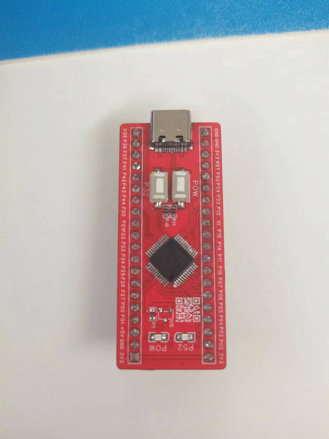
STC32G
STC32G12K128-35I-LQFP48 core board
1. Powered via USB-C, with a 5.1k resistor pulling the CC pin down to GND.
2. Almost all I/O ports are brought out, using two sets of header pins, similar to the size of LCSC development boards.
3. A TL431 is connected to VRef to ensure ADC accuracy.
5. A 32.768kHz crystal oscillator is provided for testing RTC accuracy
. 6. One user button and one user indicator light.
7. Power supply can be selected from 3V or 5V.
8. No USB-to-serial adapter is needed; STC has a convenient USB-HID download
environment setup
. Simply download Keil C251 and STC-ISP. The corresponding pack for STC32G can be installed in STC-ISP, and you can start using it.
PDF_STC32G.zip
Altium_STC32G.zip
PADS_STC32G.zip
BOM_STC32G.xlsx
93567
electronic


 京公网安备 11010802033920号

 JQX-105F-4L/277A1ZF


