The main control chip is the EG1162
, a high-power synchronous rectification buck controller with overcurrent and short-circuit protection, and an external power MOSFET.
The design
is for powering a radio, requiring a constant output voltage of 13.8V (23A output current when the radio is transmitting at full power). Therefore, the circuit was designed to handle up to a 30A limit.
The input voltage is provided by eight series lithium iron phosphate transistors, not exceeding 29.2V. The power MOSFETs should ideally have a withstand voltage of 60V or higher, with minimal internal resistance and junction capacitance. I used HD50N06D transistors from LCSC (16 RMB off with a coupon), but I'm not sure if it's due to high internal resistance or something else, but the heat is mainly concentrated in the upper half-bridge MOSFET section, while the lower half-bridge MOSFET doesn't get very hot, and the soft switch is also
affected. I strongly suspect that parallel transistors increase switching losses! If possible, use transistors with lower internal resistance and better performance!!
Speaking of soft switching, this power supply uses a soft switch with two MOSFETs connected in parallel at the negative input, which generates virtually no heat and solves the switching problem. Since
the ripple
is for powering the radio, the output ripple needs to be as small as possible. Therefore, according to the description in the EG1162 datasheet:
$$
L = frac{V{out}(V{in}-V{out})}{V{in}F{s}{I{ripple}}}
Delta V_{out}=Delta I_L (ESR+frac{1}{8 F_s Co})
$$
where $I{ripple}$ and $Delta I_L$ both refer to the current ripple on the inductor. I don't know why the datasheet uses two symbols. $C_o$ is the output capacitor, $ESR$ is the equivalent series resistance of the output filter capacitor (which can be found in the capacitor manufacturer's datasheet), and $F_s$ is the operating frequency.
Based on the above formula, a $L=47uH$ iron-silicon-aluminum magnetic ring inductor is selected for the output inductor, with a current of 30A. >>>Buy inductors on Taobao<<<.
The original operating frequency was set at 180kHz, but testing revealed severe overheating, likely due to excessive switching losses. Lowering the frequency to 90kHz improved the situation.
For the output capacitors, I chose two 470uF solid-state capacitors plus several MLCCs, which should result in relatively low ESR. Using ESR = 15mΩ, Vin = 25.6V, Vout = 13.8V, and F_s = 90kHz, I calculated approximately Delta IL = 1.5A and Delta Vout = 25mV. I'm not sure if this calculation is correct.
For safety, I added a pi-type filter after the output, using a 2.2uH inductor. I'm unsure about attenuation calculations, but a simulation in Multisim 14 showed acceptable results. >>>Inductor<<<.
(I just finished the college entrance exam and haven't systematically studied circuits yet, so I have no theoretical knowledge.)
I don't have an oscilloscope or any advanced equipment, so I can't measure the ripple. If anyone has the equipment, could you help me test it?
I've drawn a bunch of NC MLCC locations on the output so you can see how to solder them. The
circuit and PCB here are slightly different from the one I used, mainly because I modified it based on issues I encountered during debugging.
A case is included; case link >>>Click me<<<.
The output voltage
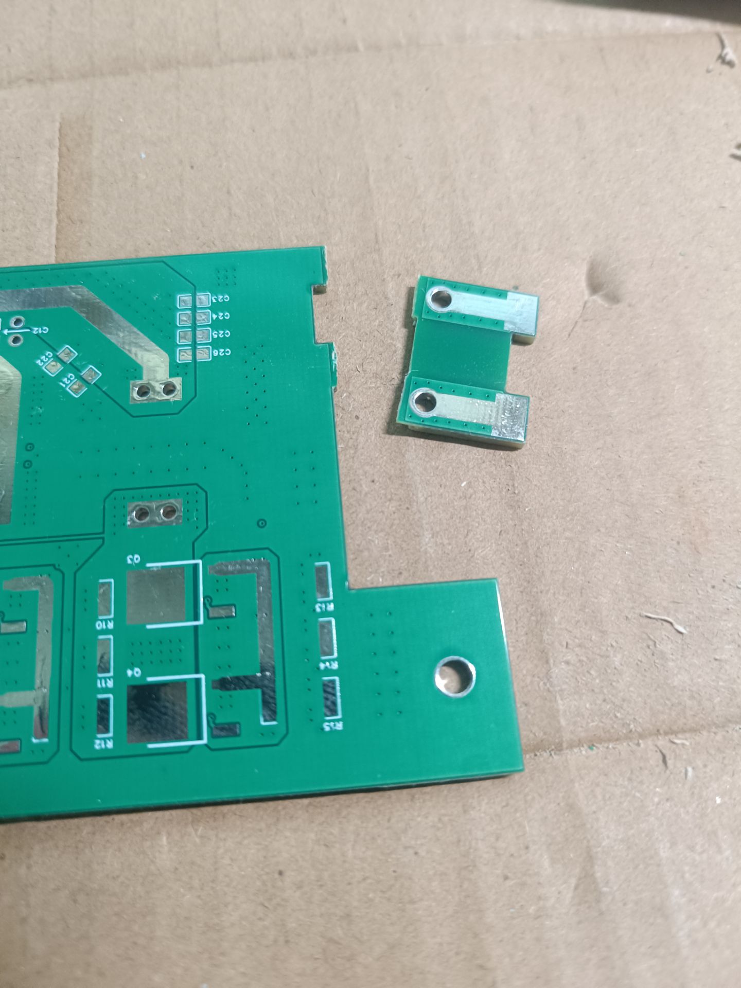
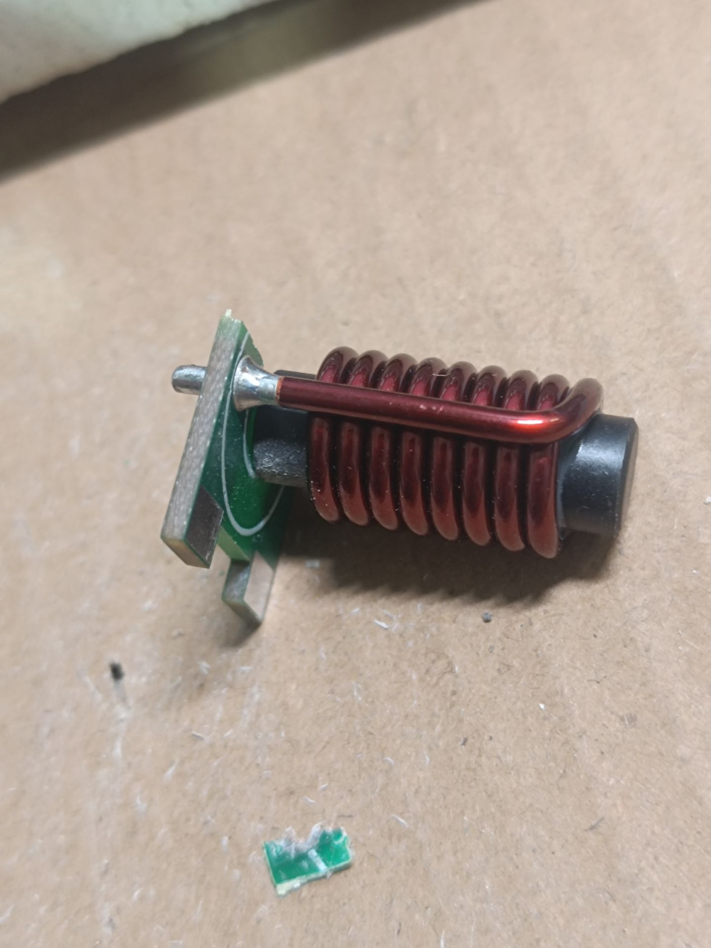
can be adjusted by adjusting the feedback resistor; please refer to the EG1162 manual for details. During testing, I used a 13.8V output with one 12715 and one 12708 external cooling chip. It boiled water very quickly (laughs), and there's a video later. Also, I've already tested it on a radio. The FT-891 can be used continuously in FM mode (100W transmitter) with almost no heat; the power supply isn't even as hot as the radio itself. A manufacturing note: cut a small piece off the board at the L2 inductor location and insert it into the slot on the mainboard. The power MOSFET is on the back of the board. For high-power operation, proper heat dissipation is crucial. I used copper sheets and silicone thermal paste to attach them to the aluminum casing. Some circuits are quite compact, such as between inductor L2 and the casing, and the output terminals. Ensure proper insulation. After installing them in the casing, apply adhesive and remember to solder or embed copper wires (the small L2 board also needs soldering!). The slots in the casing's baffle were drilled and filed by hand. The hole on top could accommodate a turnbuckle switch, but I didn't connect it here and just ran the wires through. Regarding known issues , I've noticed that shorting the output inductor causes a whistling sound. Is this a problem with the sampling resistor? This diagram is slightly different from the current sensing section in the official datasheet; I'm not sure if that's the reason. Does this mean the short-circuit protection is unusable?


 京公网安备 11010802033920号

 HF420/S012D


