 2. 3D view and physical image of the LED control board PCB .
 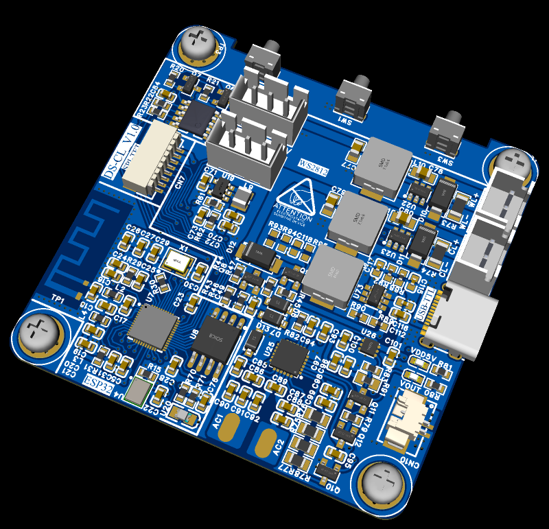 4. 3D photo of the casing (casing size is 65mm*65mm*65mm) .
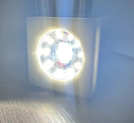
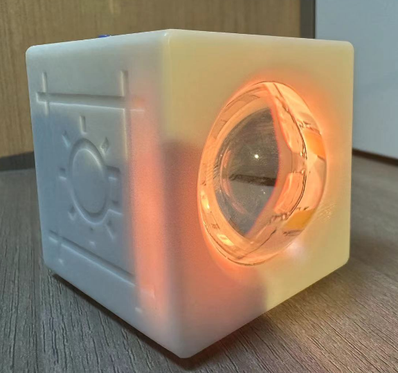
 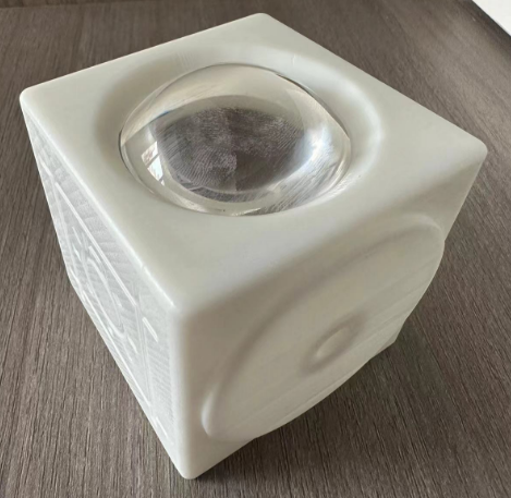 4. Physical photo
 . IV. Circuit description and usage introduction: 1. This project consists of an LED board + LED control board. The LED board is made of aluminum substrate for easy heat dissipation of the LEDs. The board has 16 5050 WS2812 LEDs; one 40V, 200mA COB LED for cool light; and 10 series 2 parallel warm white 2835 LEDs, totaling 20.
  3. The project uses the SY7301 chip for both warm and cool light. This chip is an LED current driver chip. The SY7301A features a boost DC/DC converter to provide precise, constant current to drive the LEDs. Operating at a fixed switching frequency of 1MHz, it allows the use of small-value external ceramic capacitors and inductors. The series-connected LEDs are driven by a regulated current set by an external resistor. The SY7301A is ideal for driving up to 10 white LEDs in series or up to 40V.
 5. The board's switch circuit: when the switch is pressed, IO4 detects the button action. Hardware-wise, the p-MOS conducts, and after the MCU powers on, it pulls IO19 high, forming a self-locking mechanism.
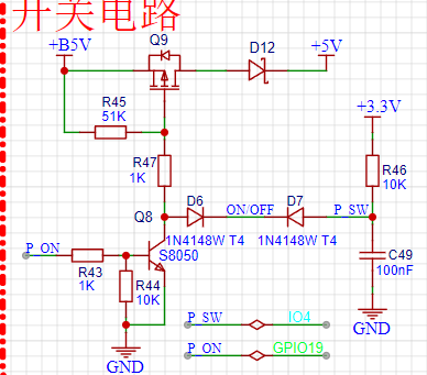
 7. The lamp's top cover uses an acrylic cover plate, also printed by JLCPCB. Below are the acrylic printing specifications. Additionally, the PCB project file also contains the printed pattern, all open-source on the project platform. (The right side shows a color screen to be added later, a requirement for upgrades; updates are available. The color screen will display color, battery level, etc.)
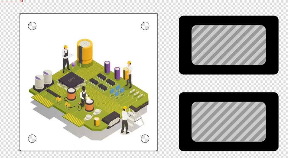

All reference designs on this site are sourced from major semiconductor manufacturers or collected online for learning and research. The copyright belongs to the semiconductor manufacturer or the original author. If you believe that the reference design of this site infringes upon your relevant rights and interests, please send us a rights notice. As a neutral platform service provider, we will take measures to delete the relevant content in accordance with relevant laws after receiving the relevant notice from the rights holder. Please send relevant notifications to email: bbs_service@eeworld.com.cn.
It is your responsibility to test the circuit yourself and determine its suitability for you. EEWorld will not be liable for direct, indirect, special, incidental, consequential or punitive damages arising from any cause or anything connected to any reference design used.
Supported by EEWorld Datasheet
EEWorld
subscription
account

EEWorld
service
account

Automotive
development
community

Robot
development
community

About Us Customer Service Contact Information Datasheet Sitemap LatestNews


Room 1530, 15th Floor, Building B,
No.18 Zhongguancun Street,
Haidian District,
Beijing, Postal Code: 100190
China
Telephone: 008610 8235 0740
 京公网安备 11010802033920号

 WJ1111C24VDC.25Z


