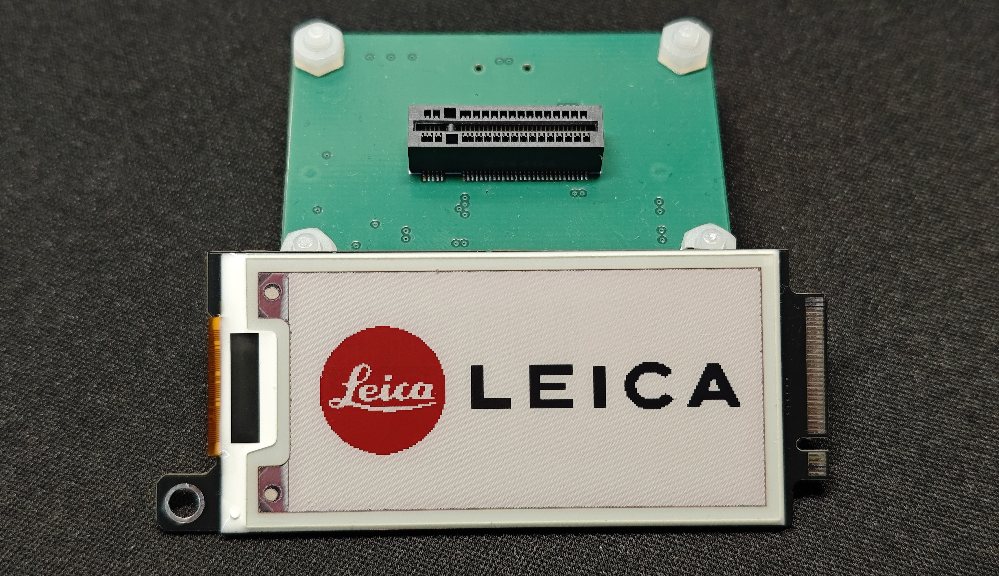
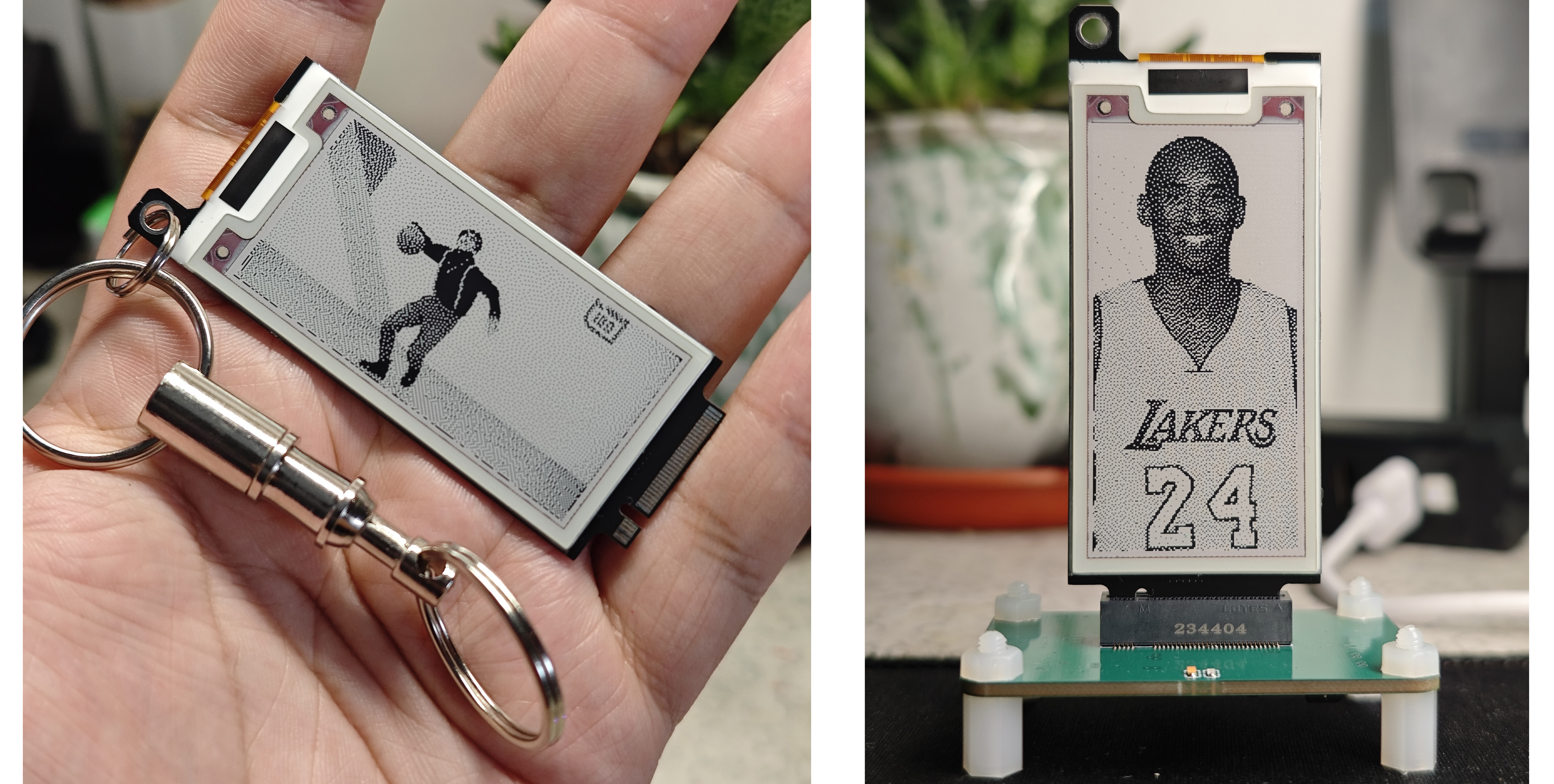
This three-color e-ink desktop ornament & portable pendant
is based on the Air001 microcontroller. It uses an M-Key to connect the e-ink card and the base plate. Plug it in to make it a desktop ornament, and unplug it to make it a portable pendant.
Updating images doesn't require re-burning code; data is written using a host computer and serial port, making it convenient and fast. The
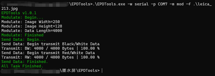
host computer supports red, black, and white three-color image capture, black and white color dithering, and QR code generation. The hardware includes a 2.13-inch e-ink screen from "Lao Wu Digital Home Electronic DIY Components" ("2.13-inch E-ink Label Screen, Brand New, No Aging, See Introduction"). The purchase link is: [link to 2.13-inch E-ink Screen Purchase Link] . This is actually an e-ink label; you need to remove the e-ink screen yourself. It's very simple; it arrives like this. Use a flathead screwdriver to pry open the arrow position. Be careful not to pry too deeply. I didn't want to disassemble it, so I didn't demonstrate. Inside, there's an e-ink screen glued to a PCB. Disconnect the FPC on the back of the screen, and use a utility knife to slowly separate the screen and PCB through the gap. You can keep the PCB; it has many useful components. This project requires two boards: a four-layer baseboard (left side) and a two-layer driver board for the e-ink display (right side). **Important ! ** The driver board ( right side) must be inserted into the M-Key interface and must be 0.8mm thick! The baseboard (left side) can be a standard 1.6mm thick board. A 24-pin FPC connector is required for the baseboard. However, since the driver circuitry of the card and the PCB removed from the e-ink label are identical, components from the removed PCB can be directly transferred to the M-Key card. The microcontroller uses the AIR001 chip from Hezhou. Recommended purchase link: AIR001 purchase link . Original driver connection? From Jiaxian: 2.13-inch e-ink screen driver connection. Other less common materials recommended purchase links: Small turtle buttons for BOOT and RST buttons: 3*4 small turtle buttons purchase link. Vertical M-Key surface mount slot: M-Key slot. The M-Key I bought here has an incorrect fixing pin size; cut it off, or try another supplier. After soldering, configure the Arduino development environment for the Air001, download the Arduino project for the lower-level machine, and burn it. How to configure the Arduino project for the Air001: AIR001 Arduino documentation. Notes when burning: In Arduino IDE - Tools - Clock Source and Frequency, select "HSI 24MHZ, HCLK 48MHz," otherwise the checksum may not be sent. The software uses an open-source host computer (the latest version is available here): Gitee-EPDTools open source or download from this project attachment. This is only a basic introduction; for more detailed usage documentation, please refer to the Gitee open source link above. Note that EPDTools.exe depends on opencv_world452.dll; it will not run if it is missing. Insert the card into the baseboard and connect the baseboard to the computer using a Type-C cable (I believe that everyone in the electronics field should have the CH340 driver installed). Open a terminal or command prompt in this directory and enter the following command: .EPDTools.exe -w serial -p COM7 -m mod -f file path. Command explanation: Use the modulo method (-m mod) to transmit data to the device through the serial port with serial number "COM7" (-p COM7) (-w serial). Your computer may not have COM7; please pay attention. You can also create two batch files in the same directory (using COM7 as an example), one for easy modulo extraction (mod_COM7.bat): `.EPDTools.exe -w serial -p COM7 -m mod -f %1` and the other for easy color dithering (dith_COM7.bat) : `.EPDTools.exe -w serial -p COM7 -m dith -f %1`. This way, you can simply enter the path to the `.mod_COM7.bat` file; you don't need to remember command-line parameters or those complicated Enter key presses. If there are no problems, it will output logs as shown in the image below, transmitting the image to the e-ink display's lower-level machine. A lit LED on the left side of the e-ink display's base plate indicates the base plate is in a ready state, while a flashing LED on the right side indicates it's in a data transmission/reception state. Data can only be written when it's in the ready state. A reset will force it back from the transmission/reception state to the ready state. Known BUG 1) When the serial port number is a two-digit number, such as COM16 or COM25, the upper-level machine cannot open the serial port. There is currently no fix; you can try plugging the device into a USB port with a lower COM port number.


 京公网安备 11010802033920号

 AME8550AEETB270Z


