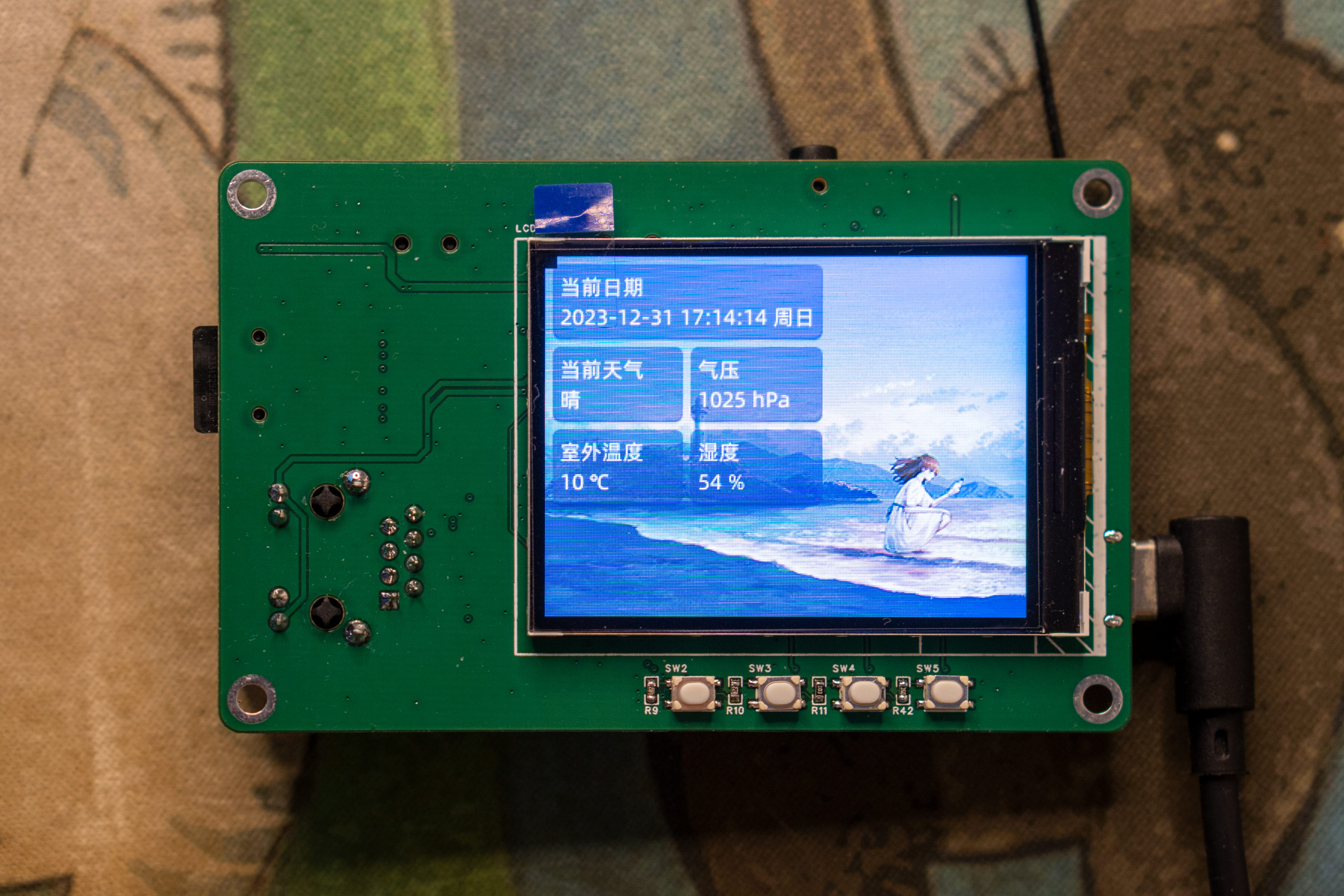
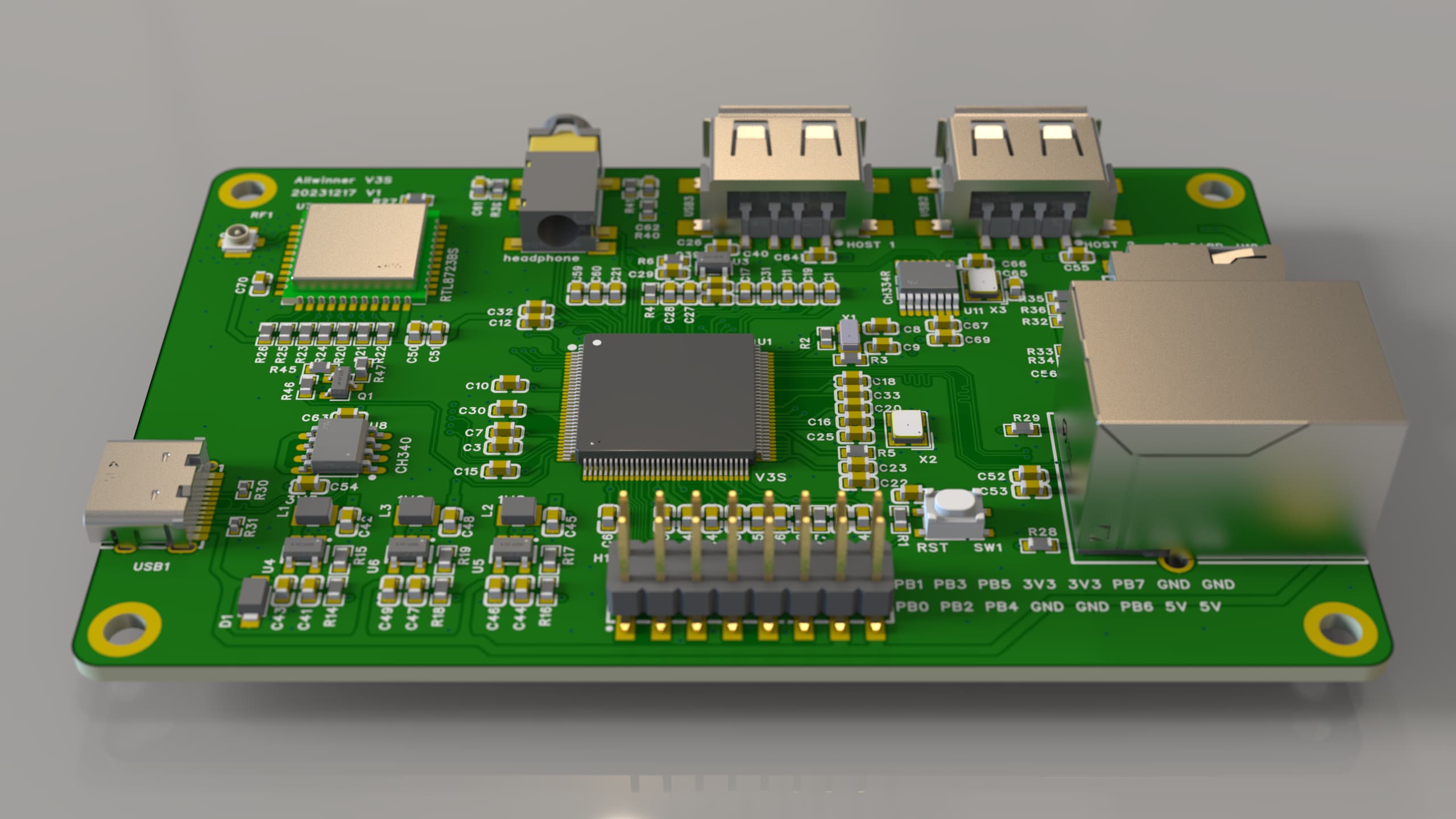
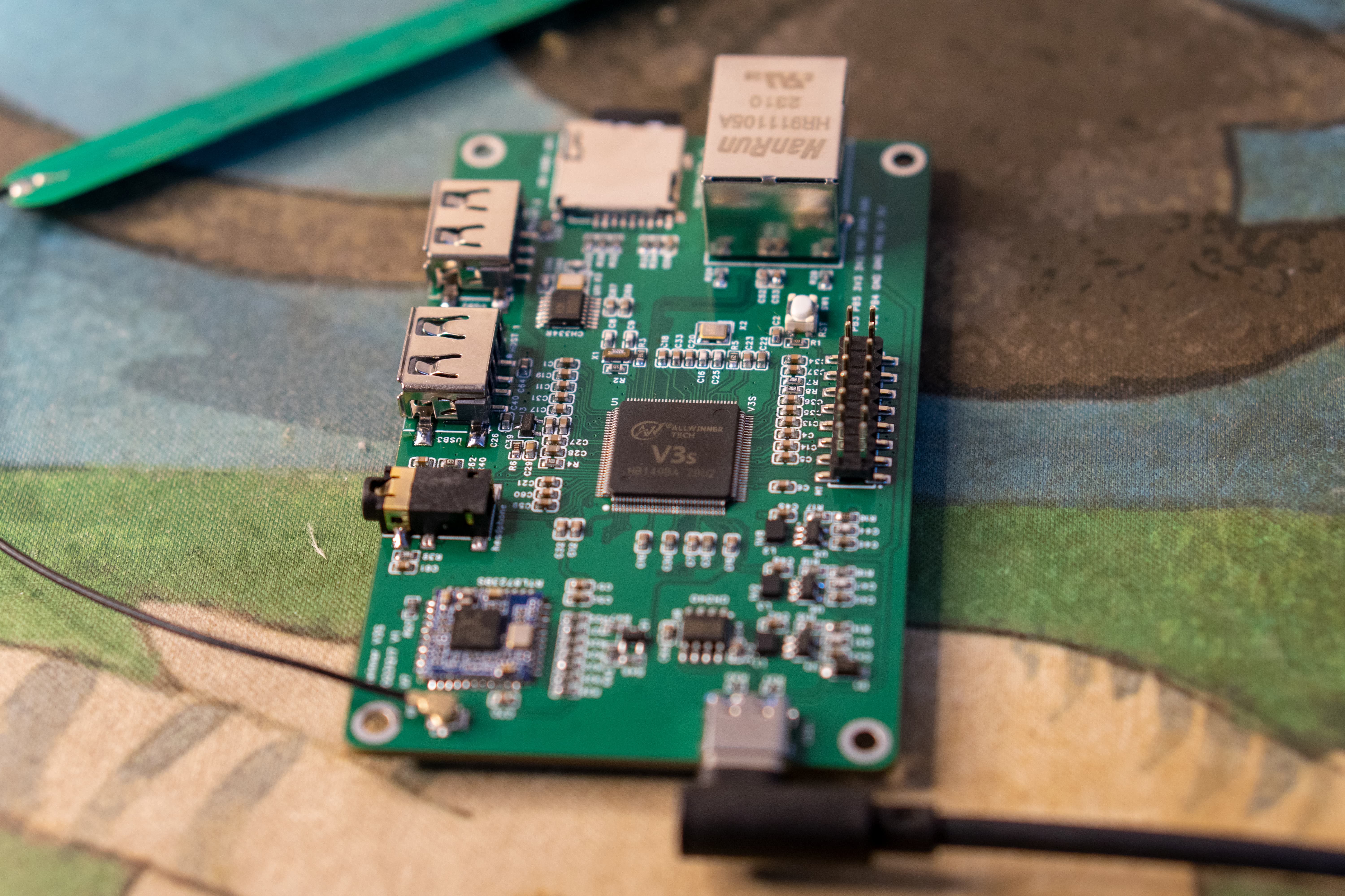
The V3S-PI portable terminal is based on the Allwinner V3S chip.
Remember the ESP32-S3-PIE released last year? After completing that project, it was discovered that the ESP32 chip was practically unusable. So, at the end of this year, the author learned Linux, starting with the F1C200S, and after thoroughly understanding the Allwinner platform, created a portable terminal based on the V3S chip. After half a month of debugging, the project is basically working.
The V3S-PI portable terminal is based on the Allwinner V3S chip. The project uses a four-layer board, with all boards using 0603 capacitors and resistors, which is easier to manufacture than 0402, and the cost can be reduced to below 100.
Update Log
2023/12/31 First Release
Chip Overview
The Allwinner V3S processor integrates a single ARM Cortex-A7 CPU, which runs at up to 1.2GHz and supports numerous peripherals. The processor addresses the growing demand for automotive digital video recording (DVR) and IP camera (IPC) monitoring systems. The 512Mbit DDR2 memory is highly integrated in the V3. Furthermore, the V3S features optimized external memory interfaces for SpinAND/NOR flash memory and SD/MMC. A dedicated video engine is included to provide advanced multimedia applications and services. The video engine supports multiple formats, such as 720p @ 60FPS, H.264 decoder, and 1080p.
Product Features:
1. Allwinner V3S main controller, using a single-core Cortex-A7 with hardware floating-point capability, a significant improvement over the A9 core of the F1C200S;
2. 64Mbyte DDR2 memory is integrated into the chip, eliminating the need for an external DDR2 chip;
3. RTL8723BS 2.4G WIFI (SDIO interface);
4. Dual USB ports via CH334R expansion;
5. Headphone jack, using the V3S built-in sound card;
6. 10M/100M Ethernet interface;
7. SDMMC interface for system boot;
8. CH340N serial-to-USB adapter for connecting serial terminals;
9. LRADC, four ADC buttons (not yet functional);
10. 2.4-inch LCD color screen using SPI interface;
11. 2x8 expansion interfaces for I2C/UART expansion. Based on existing online
resources
, the author has ported the mainline kernel, U-boot, and root functionality. Currently, it only supports SD card and SPI Nor boot; please do not refer to the current code for SPI Nand boot. For
hardware decoding, please consider using the 5.4 kernel packaged by a reputable developer.
UBoot:
https://gitee.com/fhcloud/uboot-v3s
Quick Start:
`git clone https://gitee.com/ fhcloud
/uboot-v3s` `cd uboot-v3s`
`make v3s_pi_defconfig` The output file of `
make`
is in the source code root directory: `u-boot-sunxi-with-spl.bin`
Linux
: https://gitee.com/fhcloud/linux-v3s
Quick Start:
`git clone https://gitee.com/ fhcloud/linux-v3s` `cd linux-v3s` ` make v3s_pi_defconfig` The output kernel file of ` make` is in `arch/arm/boot/zImage` Please use `arch/arm/boot/dts/sun8i-v3s-pi.dtb` for the output device tree. Buildroot: https://gitee.com/fhcloud/buildroot-v3s Quick Start: `git clone https://gitee.com/fhcloud/ buildroot-v3s.git` `cd buildroot-v3s` ` make v3s_pi_defconfig` The make output file is located at output/images/rootfs.tar. Test image username: root, password: 123456. Hardware open source : LCPI open source documentation: http://wiki.lcmaker.com/index.php?title=LC-PI-V3S V3S Chip Datasheet: (See attachment) Allwinner_V3s_Datasheet_V1.0_2.pdf V3S Hardware Design Guide: (See attachment) V3s Hardware Design Guide V1.0_20150519.pdf V3S Reference Schematic (for reference): (See attachment) V3S_CDR_STD_V1_0_20180322.pdf 2.4-inch Color Screen Datasheet: (See attachment) LH240K-IG01.pdf Material Reference Purchase Address: V3S (This one is probably refurbished, but it works): 2.4 '' Color Screen (Select 18-PIN Soldering): [Link 1] Surface Mount Header (Select 2*8P): [Link 2] USB female connector (select four-pin surface mount (black glue/with edge)): https://item.taobao.com/item.htm?_u=v2dklb45a979&id=644273830279&spm=a1z09.2.0.0.21792e8dncSlgg CH334R (select CH334R):
RTL8723BS: https://item.taobao.com/item.htm?spm=a1z09.2.0.0.21792e8dncSlgg&id=685199066514&_u=v2dklb454d3a Headphone jack (PJ-342, gold-plated 3.5mm headphone jack (5 pieces)):
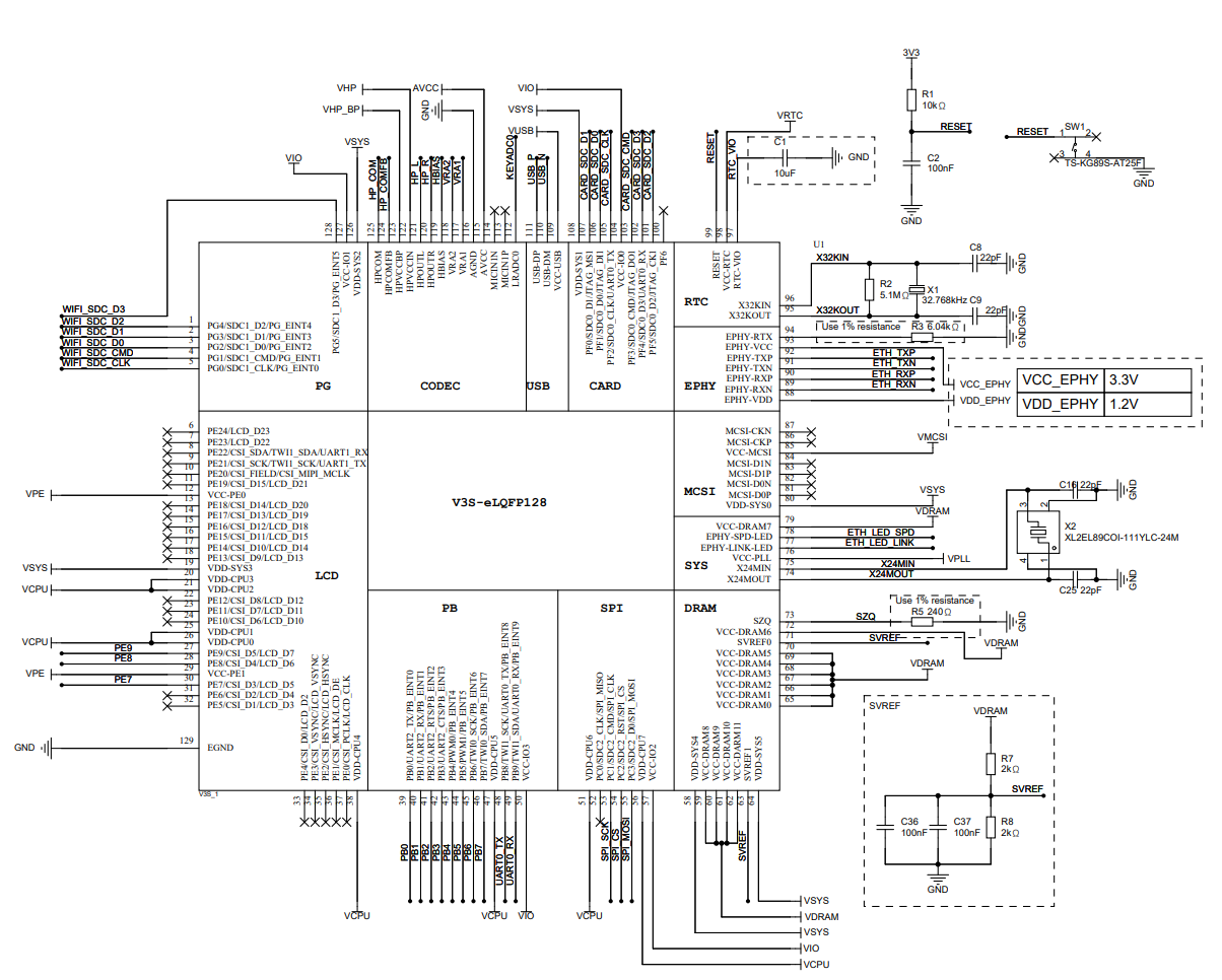
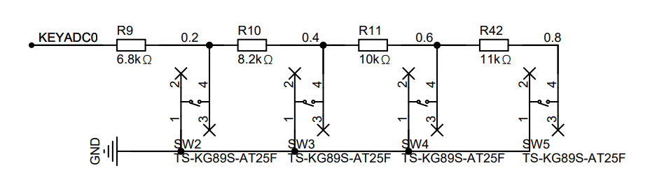
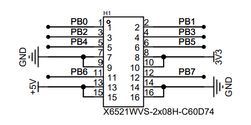
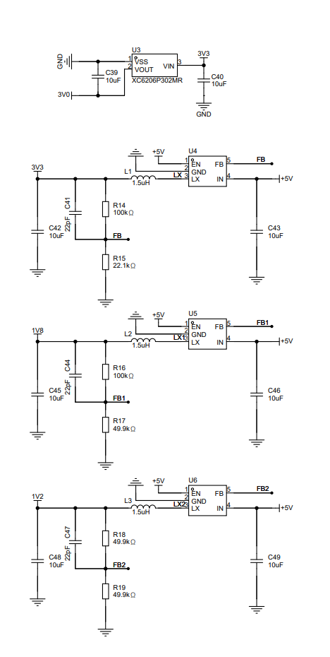
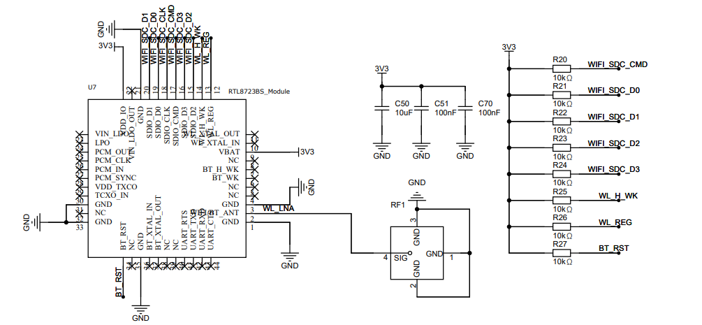
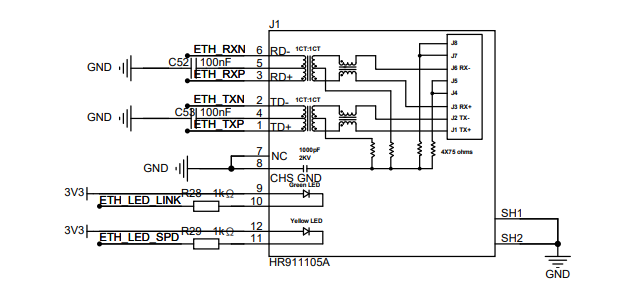
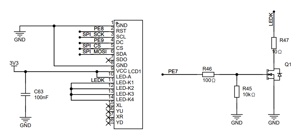
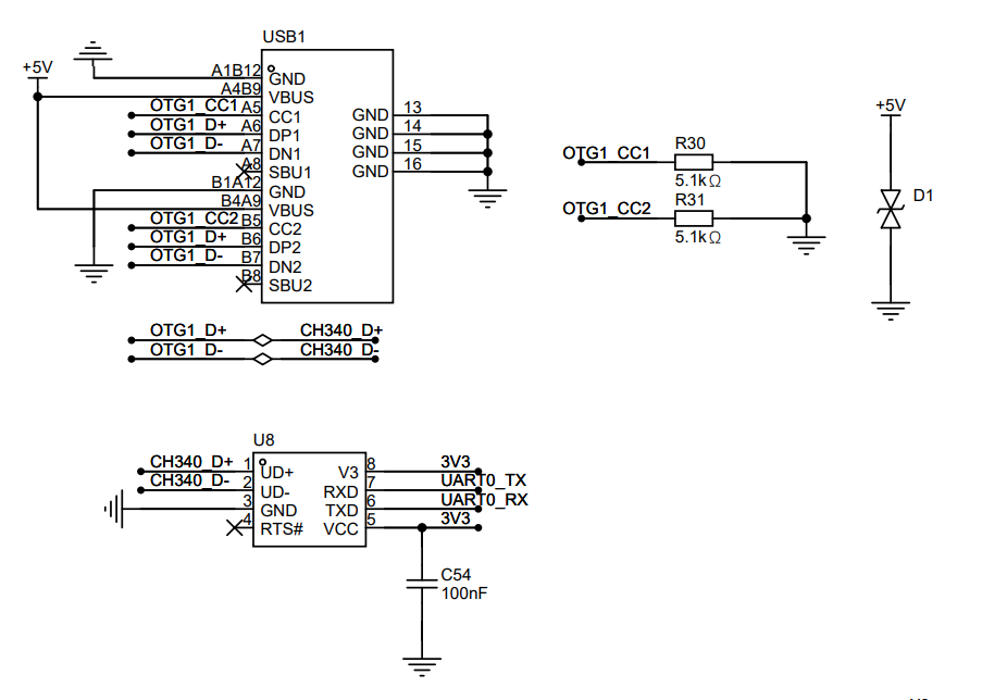
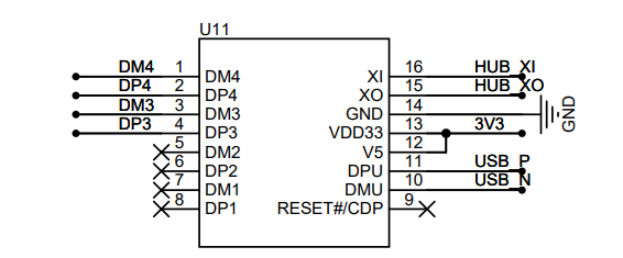
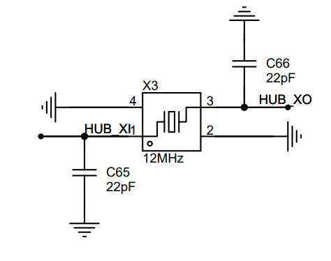
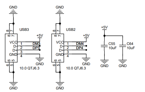
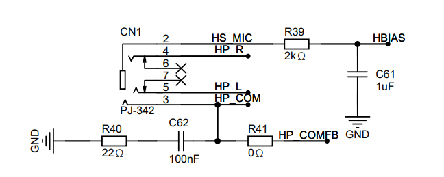
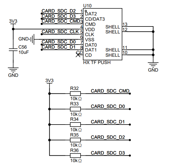
https://item.taobao.com/item.htm?spm=a1z09.2.0.0.21792e8dncSlgg&id=601770157864&_u=v2dklb45bf86 HR911105A RJ45 connector (this one is probably a pirated copy, but it works): https://detail.tmall.com/item.htm?_u=v2dklb4575c2&id=14476732895&spm=a1z09.2.0.0.21792e8dncSlgg SD card slot (just find a similar one on Taobao, no need for LCSC): https://item.szlcsc.com/5851216.html IPEX connector: Taobao, select (IPEX... ) The hardware solution for this project uses the Allwinner V3S main controller , as detailed above. Note that resistors R3/R5 must be 1% ohms. Also, the EPHY has two voltage levels, as shown in the schematic below. See Figure 1 for the schematic: Figure 1: Main Controller Schematic. The ADC button board has four ADC buttons with a voltage span of 0.2V, achieved through voltage divider resistors. The schematic for this module is shown in Figure 2: Figure 2: ADC Buttons . The 2x16 PIN expansion interface uses pin headers to bring out eight expansion interfaces, including one serial port and one I2C bus, which can be used to connect other devices. See Figure 3 for the schematic. Figure 3 shows the auxiliary power supply board with four sets of power supply chips, generating 3.0V, 3.3V, 1.8V, and 1.2V respectively. 3.0V is used for PLL and AVCC analog power supply, 3.3V is responsible for chip I/O and other peripheral power supply, 1.8V is used for memory power supply, and 1.2V is used for V3S core main control power supply. The maximum output current of the three DC-DC converters is 2A. The schematic diagram of this part is shown in Figure 4. Figure 4 shows the auxiliary power supply WIFI module board with an onboard 2.4G WIFI module using an RTL8723BS module. The V3S and WIFI module are connected via an SDIO interface, with an IPEX interface for connecting an external antenna. R20-R27 are pull-up resistors required by the SDIO and the chip, and C50/C51/C70 are external filter capacitors. The module uses a 3.3V power supply. Figure 5 shows the schematic diagram of the WIFI module. The 10M/100M Ethernet interface requires two sets of differential pins, RX/TX differential. Ethernet PHYs generally have an automatic flip-flop function, so RX/TX can be swapped. V3S Ethernet uses voltage drive; simply add a 100NF capacitor to ground at the center tap of the network port transformer. The internally packaged resistors and 2KV capacitors are used to discharge static electricity from the motherboard to prevent high voltage damage to the main control chip. R28/R29 are LED current-limiting resistors. SH1 and SH2 are the outer casing and can be directly grounded. The schematic diagram for this part is shown in Figure 6. Figure 6 shows the schematic diagram of the Ethernet interface . The 2.4 '' LCD color screen communicates with the main controller via SPI. PE8 is connected to the screen reset line, and PE9 is connected to DC to distinguish between data and commands. LEDA is the backlight anode, and LEDK is connected to Q1 MOS for the main controller to control the backlight switch. The screen is soldered to the PCB board. The schematic diagram for this part is shown in Figure 7. Figure 7 shows the schematic diagram of a 2.4'' LCD color screen. The CH340 serial-to-USB converter uses the CH340N chip to achieve serial-to-USB conversion for computer connection to terminals. R30/R31 ensures proper power supply to the dual-ended Type-C cable. D1 is a TVS converter to protect the USB interface. A 3.3V power supply is used here, so VCC and V3 of the CH340N need to be connected together, and a 100nF capacitor should be added (refer to the CH340N manual for details). The schematic diagram for this part can be found in Figure 8: Figure 8 CH340 Serial-to-USB Converter. The CH334R 1-to-4 USB HUB uses the CH334R chip to achieve a 1-to-4 USB host port conversion. A unified power supply is used here, so VDD33 and V5 can be connected together. XI XO is the input for a 12MHz crystal oscillator, and the DPU/DMU is connected to the upstream USB port. Figure 9 CH334R Schematic Diagram Headphone Jack The headphone jack uses the PJ-342 interface, which includes audio and recording functions. Refer to Figure 10 for the schematic diagram of this part: Figure 10 PJ-342 Headphone Jack SD Card Interface The SD card interface is used to insert a MicroSD card. R32-R36 are pull-up resistors for the SD card. CLK does not need to be pulled up, otherwise it may affect SDIO communication. Refer to Figure 11 for the schematic diagram of this part. Figure 11 SD Card Interface Software Solution The Linux kernel uses the Linux 5.15.143 mainline kernel. Based on this, some code has been modified to adapt to most V3S peripherals. The 2.4-inch LCD color screen driver uses an SPI interface to connect to the main controller. The software uses TinyDRM, which, compared to traditional FBTTFT, no longer refreshes at a fixed frame rate. It also adopts a DRM architecture, allowing for faster integration with newer architecture programs. Because the initialization code differs between screen manufacturers, the initialization code in the st7735r.c file has been modified. Following the original code, we only need to modify the code in the st7735r_pipe_enable function. The modified code can be found in the following file: https://gitee.com/fhcloud/linux-v3s/blob/master/drivers/gpu/drm/tiny/st7735r.c#Device Tree Configuration Reference: &spi0 { status = "okay"; pinctrl-names = "default"; pinctrl-0 = ; display@0 {
compatible = "jianda,jd-t18003-t01";
reg = ;
spi-max-frequency = ;
backlight = ;
dc-gpios = ; // PE9
reset-gpios = ; // PE8
rotation = ;
};
};
In addition to spi, a backlight node needs to be added so that the backlight can be operated at the user level:
panel_backlight: panel-backlight {
compatible = "gpio-backlight";
gpios = ; // PE7
default-on;
status = "okay";
};
USB
device tree configuration reference:
&usb_otg {
dr_mode = "host"; // peripheral
status = "okay";
};
&usbphy {
status = "okay";
};
In addition to the reference node, ochi/echi must be added, otherwise there will be no response when the USB is plugged in:
soc {
ehci0: usb@01c1a000 {
compatible = "allwinner,sun8i-v3s-ehci", "generic-ehci";
reg = ;
interrupts = ;
clocks = , ;
resets = , ;
status = "okay";
};
ohci0: usb@01c1a400 {
compatible = "allwinner,sun8i-v3s-ohci", "generic-ohci";
reg = ;
interrupts = ;
clocks = , ,
;
resets = , ;
status = "okay";
};
};
For Ethernet
, simply reference the emac node in the DTSI file. Device tree reference:
&emac {
allwinner,leds-active-low;
status = "okay";
}; For
wireless network card RTL8723BS,
the SDIO architecture under Linux is similar to USB. After the device is plugged in, if there is a corresponding driver, it will be automatically loaded. Therefore, in the device tree, we only need to configure the MMC1 interface, compile the corresponding driver ko, and load it in the rootfs. Device tree configuration reference below:
&mmc1 {
broken-cd;
bus-width = ;
vmmc-supply = ;
status = "okay";
};
For WIFI configuration, please refer to: https://zhuanlan.zhihu.com/p/665212465?utm_id=0
The compiled .ko file is located in the overlay directory of buildroot. You can refer to the following:
https://gitee.com/fhcloud/buildroot-v3s/tree/master/board/v3s-pi/overlay/usr/lib/modules/5.15.143-v3s-pi+r8723bs.ko
This is the compiled kernel module. This module backports the driver for the 5.19 kernel, which is more stable than the driver for 5.15.
In addition to the .ko file, the network card firmware also needs to be loaded here. Refer to the directory below:
https://gitee.com/fhcloud/buildroot-v3s/tree/master/board/v3s-pi/overlay/usr/lib/firmware/rtlwifi
. rtl8723bs_nic.bin can be found on GitHub or other websites.
For Wi-Fi connection, please refer to the script below:
[root@buildroot ~]# cat conn.sh
modprobe r8723bs.The command `ko
wpa_supplicant -B -i wlan0 -c /etc/wpa_supplicant.conf
udhcpc -i wlan0` is used
to configure wpa_supplicant. Please refer to the configuration file below.
ctrl_interface=/var/run/wpa_supplicant
ap_scan=1
network={
ssid="###############"
psk="###############"
}
ADC button
test file reference below:
https://gist.github.com/FanhuaCloud/8c4cf31c040034eb75e601be6b83c315
Audio playback
Buildroot integrates ALSA, and the sound card will be muted by default. Open the terminal, type alsamixer, and first unmute:
In the current interface, select Headphone, then press the M key to unmute, and then use the up arrow key to adjust the volume to a suitable level. The interface can be seen in Figure 12:

Figure 12 alsamixer
After adjusting, type mpv filename--no-video, plug in headphones, and music playback will be enabled:
[root@buildroot ~]# mpv 2.flac --no-video
Video --vid=1 [P] (mjpeg 500x500 1.000fps)
(+) Audio --aid=1 (flac 2ch 48000Hz)
File tags:
Album: 西厢寻他
Title: 西厢寻他
Track: 1
AO: [alsa] 48000Hz stereo 2ch s32
A: 00:00:04 / 00:03:43 (2%)
Exiting... (Quit)
The command prompt displays the current directory.
Edit the /etc/profile file and add the line:
export PS1='[u@hw]$ '
Then export /etc/profile and reload the configuration.
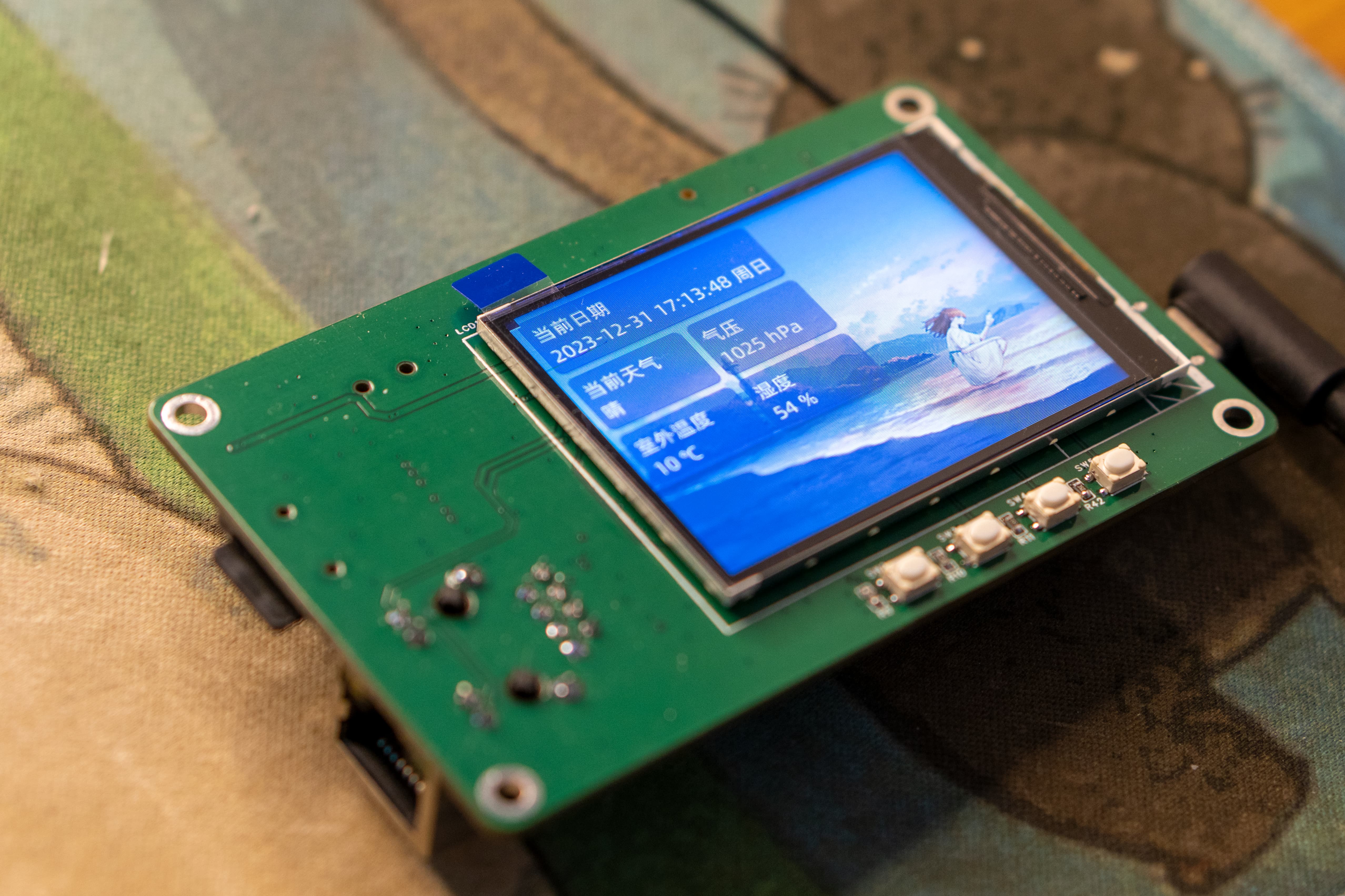
libcurl
Get the current weather using libcurl. See the program for reference:
https://gist.github.com/FanhuaCloud/c325c3c2965ef236aab644316f73f7dc
(Image shown)


In conclusion,
this article was written on the evening of December 31, 2023. At the end of 2023, I hope everyone's dreams come true, all wishes are fulfilled, everything goes smoothly, and blessings fill their families in the new year!


 京公网安备 11010802033920号

 N504100Y1EB1S


