Project Introduction:
This project is an improved version of the [BlueGo] air gesture controller. The new version abandons the previous name "air gesture controller" because that name was inaccurate. This device is inherently a collection of multiple functions, so "universal Bluetooth peripheral" is more appropriate. In fact, using the word "universal" to describe this device is actually an understatement. The device supports 13 input signals (including angular velocity sensor signals, 7 air gestures, and 5 trackball signals), enabling 28 different control types (including mouse, keyboard, touch, and electronic device operation), and also supports expansion at the code level. Therefore, theoretically, there are C(28,13) = 37,442,160 functions (combinations). Although the theoretical combinations of functions are numerous, the truly useful combinations are relatively limited in practice. This vast combination possibility is not for all practical applications, but to provide customization and flexibility. The soul of this version is flexible customization settings, easily configuring your own personalized functions. The device has several commonly used functions pre-set, such as air mouse, touch device gesture control, touch device trackball control, trackball mouse, etc.
If you encounter any software or hardware issues during the BlueGo replication process, you can join our QQ group for discussion: QQ group: 690317122.
Introductory video: https://www.bilibili.com/video/BV1AC41157nm/

Function Introduction:
This device is a BLE (Bluetooth Low Energy) based HID (Human Interface Device). It is developed based on the ESP32-pico-v3 chip and integrates a PAJ7620U2 gesture recognition module, an MPU6500 inertial sensor chip, and a trackball as input sensors. It can output four types of signals: mouse, keyboard, touch, and electronic device control. Therefore, it can control most electronic devices on the market that support Bluetooth Low Energy and can be controlled via mouse, keyboard, or touchscreen, such as mobile phones, tablets, computers, and TVs. It also integrates a 1.02-inch e-ink screen that can display device status, switch between different modes, and allows for customization of various functions. For
air mouse, touch device gesture control, keyboard button operation, and remote photography, please refer to the old project [BlueGo] Air Gesture Controller or the Bilibili video. The following will introduce the trackball mouse, mode switching, and customization functions.
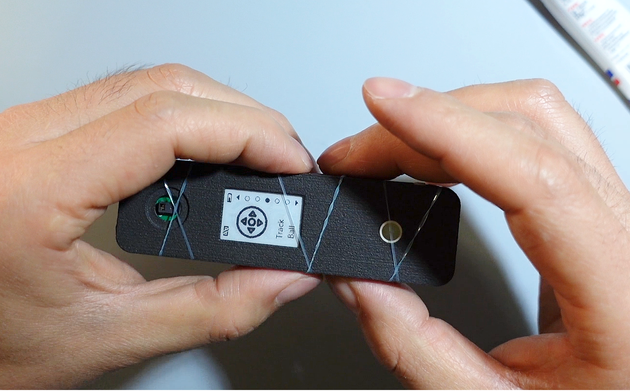
1. Trackball Mouse: It uses the same trackball as BlackBerry phones, featuring five input signals: scrolling signals in four directions (up, down, left, and right) and a button signal. The four directional input signals are detected by Hall effect sensors. The scrolling of the wheel triggers signals by moving a magnetic roller; a full rotation of the trackball triggers 11 signals. The button, located below the scroll wheel, is a tactile switch activated by pressing the trackball.

2. Mode Switching: In normal operating mode, briefly press the power button in the lower right corner to enter mode switching mode. The trackball will then turn blue. Scrolling the trackball up/down or left/right allows you to switch between different modes. Briefly press the power button again to exit mode switching; the device will then operate in the currently selected mode. If the data format changes after switching modes, the system will prompt you to restart the device. After restarting, you need to unpair and repair the trackball on the host device to use the new mode.
3. Customization Function: After entering mode switching mode, scroll the trackball to select the desired custom mode, then briefly press the trackball twice to enter the function customization page. On this page, users can enable or disable input signal modules (including IMU, gesture recognition sensors, and trackball). Once each input signal is enabled, users can individually edit its corresponding control signal, categorized into four types: mouse, keyboard, touchpad, and electronic device control signals. Use the trackball to scroll through the selections, and press the trackball to enter the specific signal selection page. Control signals are displayed in a radio button list; after selecting the desired signal, press the trackball to confirm the selection, or long-press the trackball to exit the selection state. After selection, users return to the custom settings page to continue configuring other input signals.

Below is a diagram showing the input and output signals in both Chinese and English on the settings page (click to view a larger image).

Device Code:
ESP32 Code (based on ESP-IDF): GitHub - GeekFantasy/bluego-esp32, Gitee - GeekFantasy/bluego-esp32
Material Module:
Main Controller: ESP32-Pico-V3
IMU: MPU6500
Gesture Module: PAJ7620U2 Taobao
Battery Management: TP4056
Trackball: Panasonic EVQW JN500 Taobao
E-ink Screen: GDEW0102T4 Taobao
Lithium Battery (3.7V): 300 mAh, Model: 402530, Dimensions: Thickness: 4mm, Length x Width: 25mm x 30mm (Batteries smaller than or equal to this size can be used. The original purchase link is invalid; please find and purchase elsewhere.)
AN48841B-NL: Taobao
FPC connection cable: LCSC (Listron Corporation)
lens and lens ring: Select 11 lens and outer ring Taobao
glue: Taobao
device casing: needs to be printed by yourself, 3D model see project attachment.
Replication Instructions:
1. Only the circuit board BlueGo-v2.1.1 and Gesture need to be made for replication. Other circuits are older versions and module circuits, which can be ignored.
2. The attached casing model is based on a 1.2mm PCB thickness design.
3. It is best to solder the battery from the back of the PCB, with the positive terminal soldered to the BAT pin and the negative terminal soldered to GND.
4. LED4 is already shorted in the circuit and does not work, so it does not need to be soldered.
5. When installing the lens in front of the gesture sensor, it needs to fit very closely to the sensor surface, otherwise it will affect gesture recognition (refer to assembly instructions 5).
6. Device firmware, flashing tools, and operating steps are in the project attachment.
Firmware Description:
1. The firmware was developed using VS Code and the official ESP-IDF development kit;
2. It uses C language and is based on ESP32-IDF 4.4;
3. It integrates the Lvgl graphics library 8.3.11.
Instructions for Use:
1. Verify device functionality: Use a Bluetooth-enabled phone, tablet, or computer to access the system's Bluetooth management interface and search for nearby devices. If a device named "BlueGo" is found, the device is functioning correctly.
2. If the device uses the air mouse function, please place it still immediately after startup and wait for the IMU to automatically correct the offset; otherwise, the mouse will drift.
3. The bottom right corner contains the power and mode control buttons. A short press turns the device on when it's off, a long press turns it off when it's on, and a short press enters the mode switching state.
4. Note when customizing settings: Gyroscope can only be set to Pointer, and vice versa; gesture control and keyboard/mouse operation cannot be set to the same mode, otherwise keyboard and mouse operation will not work.
5. UI Operation: a. Click the button on the lower right side to enter mode management mode. The trackball will turn blue. Press the button again to exit mode management mode, and the blue trackball will turn off. b. In the mode management page, slide the trackball up and down to switch between different device modes (5 preset modes, air mouse, gesture control, trackball control, and 2 custom modes). After exiting mode management, the device will work in the currently displayed mode. After switching between some modes, the system will prompt you to restart the device. After restarting, you need to delete BlueGo from the input device and re-pair it for it to work. c. On a certain mode page, double-click the middle button on the trackball to enter mode editing mode. Use the trackball to scroll and click to customize the settings for different modes. d. In mode settings, enter the radio button list page for Action selection. Slide up and down to select options. First, click the middle button on the trackball once to enter Edit mode, then click to select or deselect an option. Then long-press the button (about 1 second) to exit Edit mode. You can then scroll up and down to select options again, or click Back to exit this page.
e. In the mode settings interface, select Save to save the current settings, and select Cancel to cancel the settings.
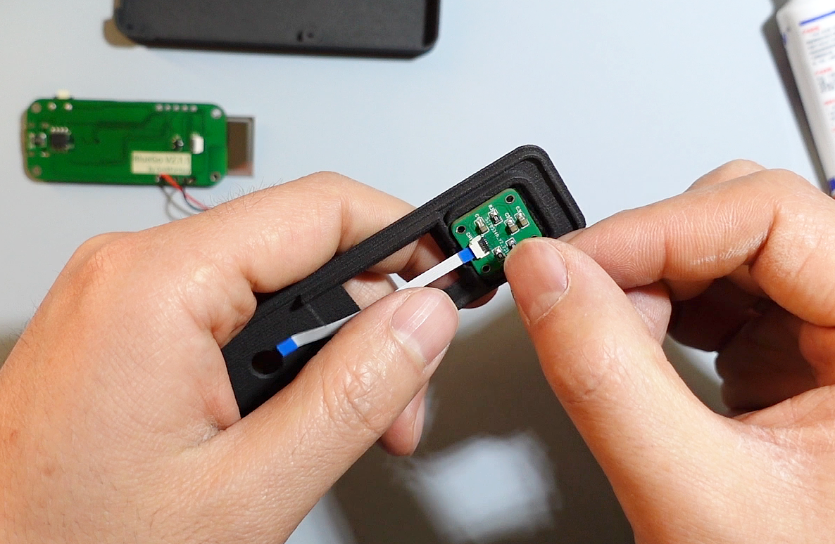
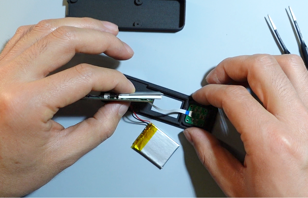
Assembly Instructions:
The hardware assembly of this version is slightly complicated. Below are some key steps:
1. Module placement on the bottom shell.

2. Apply glue to fix the gesture module.

3. Place a piece of tissue paper of appropriate thickness behind the e-ink screen to ensure a better fit between the screen and the top shell.
4. Apply glue to the inner edge of the top shell, then align and glue it firmly to the bottom shell . 5.

Reinforce the body with rubber bands and wait for the glue to cure.
6. Glue the lens ring and lens (the lens in front of the gesture sensor needs to fit very closely to the sensor surface during installation, otherwise it will affect gesture recognition).


 京公网安备 11010802033920号

 C1206X471MGRACAUTO


