Since the MAX II project was cancelled, I'm making a dual TPA3255 design as a temporary solution. There aren't many people on this site who have done this before, and only two open-source projects exist (both are quite abstract).
This design is a continuation of the previous 1794 project, completely filling the gaps in audio functionality. I've already done decoding and power amplifier work, so I won't be venturing into audio again unless absolutely necessary.
Enough rambling, let's get to the introduction.
All materials and documents for this design (schematics, datasheets, layout, heatsink CAD files, etc.) are included in the attached compressed file; please download and use them.
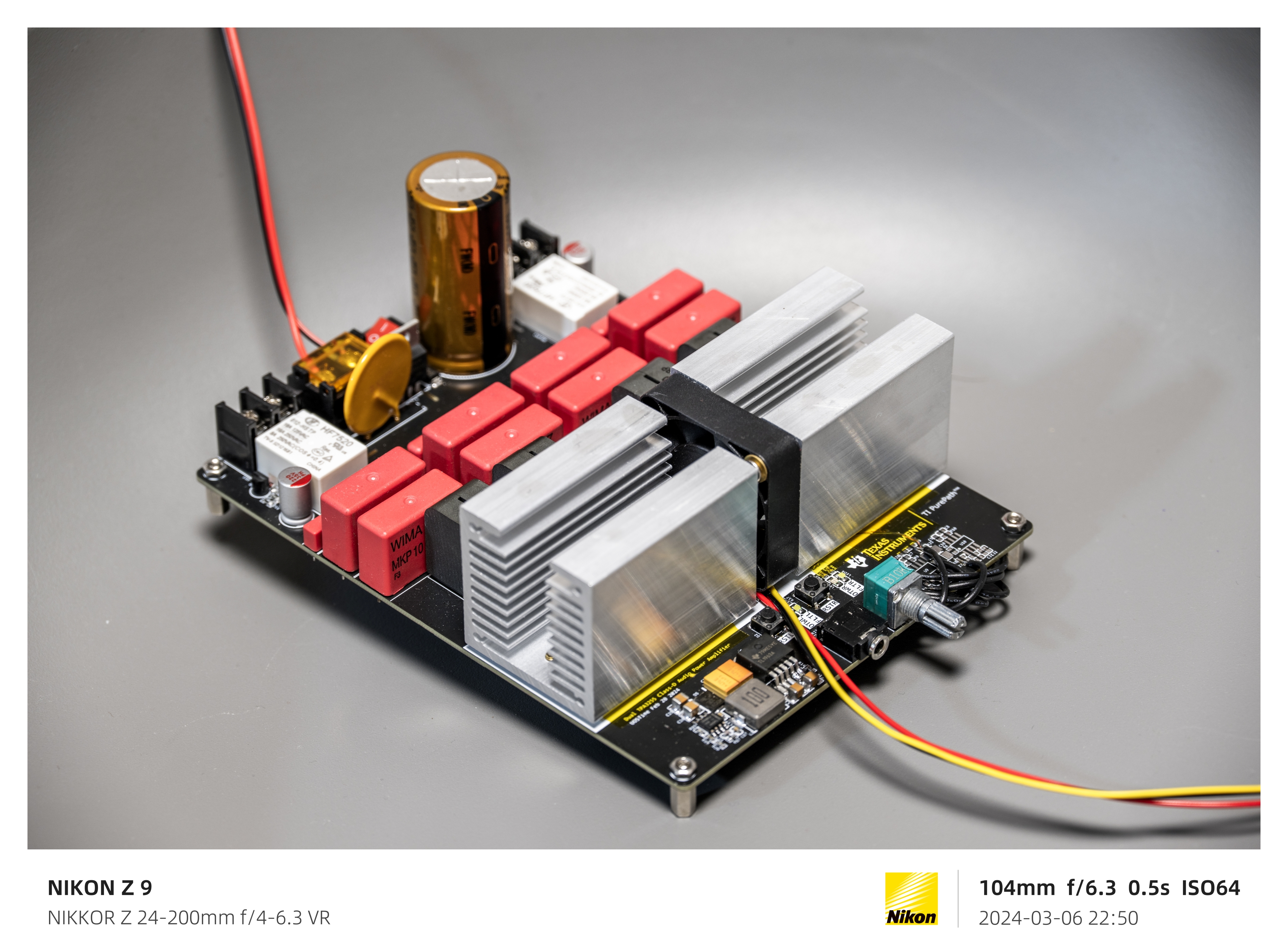
The design uses two TPA3255 chips, similar to the PCM1794. Each chip is configured in PBTL mode and dedicated to one channel, thus achieving a dual-channel output of 605W*2 (this is a theoretical value; see the datasheet and my video for details).
The audio input is single-ended, but a balanced signal can also be connected after the op-amp preamp as the input (the latter requires custom wiring based on the location).
Onboard power switch, reverse connection protection circuit, resettable fuse, and speaker protection circuit. Power supply DC 24V - DC 48V input (no rectifier bridge, must be a single DC power input!).
Onboard voltage regulator to power the preamplifier circuit and TPA3255 control logic. Except for the VIN - DC 15V channel, all other circuits use TI's ultra-low noise linear regulators.
SAGAMI 7G23B digital amplifier-specific inductors are used, but can be modified to other types. Due to having many spare WIMA capacitors at home, they were also used in the project; these can be replaced to save cost and space.
A dedicated heatsink is designed to accommodate a 4010 cooling fan for active cooling.
【Important】Notes:
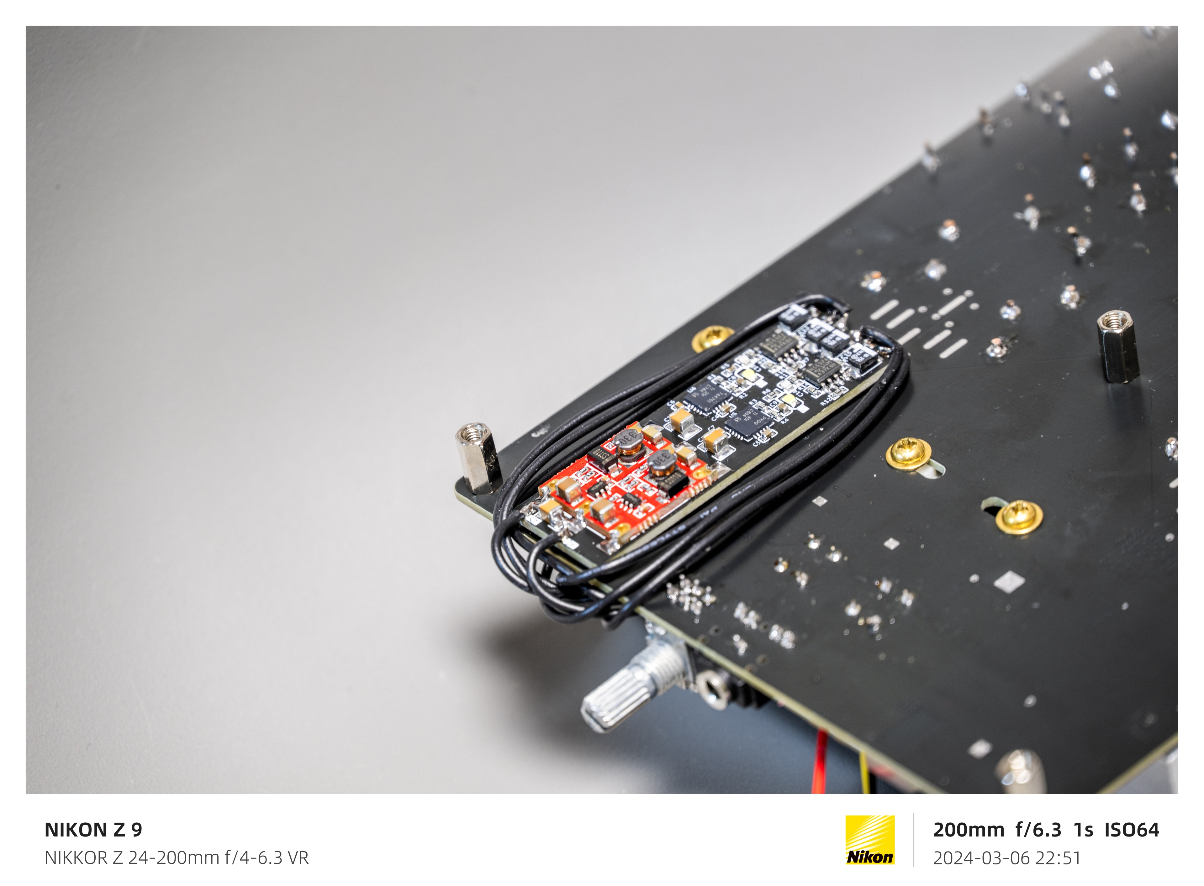
1. Due to an error in the initial PCB design, the "Pre-Amplifier" module in schematic "Board1" has been deprecated; it has been replaced by another board in the project, "Patch," whose circuitry replaces the "Pre-Amplifier" module. Do not solder the corresponding part of the "Pre-Amplifier" module in "PCB1". Construct the circuit in "Patch" according to the network name and connect the jumper wires. Connect the power supply of "Patch" to the output stage of TL1963A. You will also need to purchase a small single-supply to dual-supply module; see the "Patch" schematic for details. If possible, you can directly copy the "Patch" circuit, add it to "Board1", and delete the original "Pre-Amplifier" module. Since the project has been uploaded and locked, I cannot make any changes; please understand.
2. If you find a 10uH inductor on pin 2 "VDD" of the TPA3255 in the "Board1" schematic, please remove it and directly connect +12VL/R to the corresponding pin. According to actual testing, this inductor affects the power supply of the TPA3255 logic circuit and repeatedly triggers a reset.
I've uploaded the detailed production process and explanations to Bilibili, link: https://www.bilibili.com/video/BV1pi42197q3/
I will be migrating these projects to GitHub, my GitHub homepage: Your Repositories (github.com).
My videos are also available on YouTube, my YouTube homepage: (1165) UOSTime - YouTube.
For any questions, I suggest asking on Bilibili; the same applies to discussions. I don't check here often.
Below are some photos:


 京公网安备 11010802033920号

 2N6517


