Visible light cameras offer high resolution and frame rate, while thermal imaging sensors measure temperature distribution but suffer from low resolution and frame rate. Visible light images are used to compensate for thermal imaging images, resulting in higher-quality heat distribution maps. The device consists of a standard visible light camera and a thermal imaging sensor. After being read by an MCU, the data is transmitted to a mobile phone via USB. The phone's powerful computing capabilities enable image processing and fusion, displaying the final image on the screen (excerpt from a binocular mobile thermal imager).
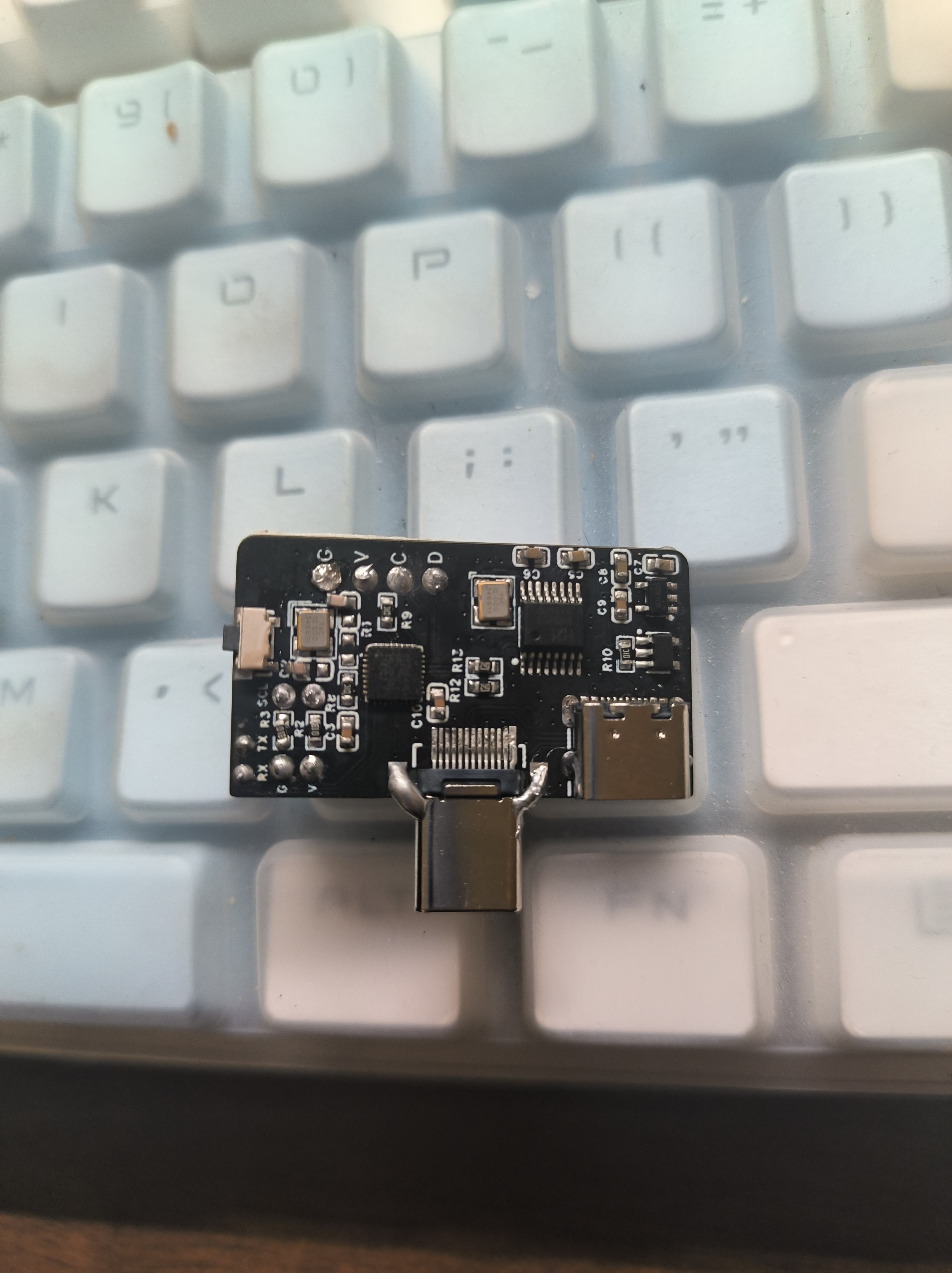
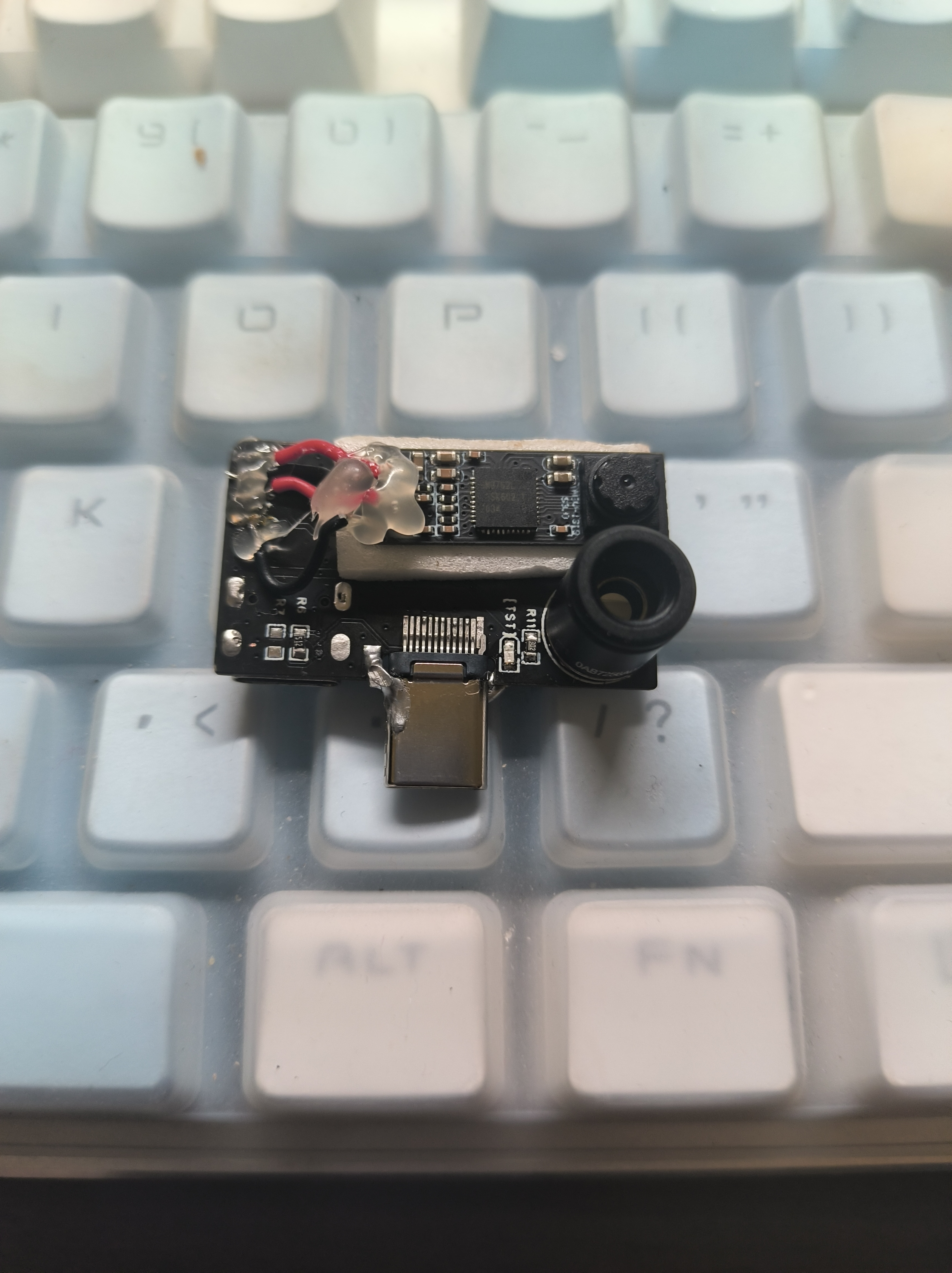
This project replicates a binocular mobile thermal imager, but with lower costs (excluding the camera, costs can be controlled to around 10 RMB). It is compatible with Android apps, although refresh rate control is not yet implemented. The hardware uses AT32F415KBU7 and CH334R, making it more compact than the original project. The project is
the MIT license, which grants the right to use, copy, modify, merge, publish, distribute, sublicense, and sell the software and copies thereof. Licensees may modify the license terms as needed for the program. The software and all copies thereof must include a copyright notice and license notice, but the original author assumes no risk of use and has no obligation to provide technical support.
The AT32F415 has a built-in crystal oscillator, so USB does not require an external crystal oscillator (saving 0.5 yuan). Although I soldered a crystal oscillator in the picture, it is not actually needed, so please do not solder it.
The AT32F415 is 2.5 yuan with free shipping on Taobao, which is cheaper than the STMF411 which costs over 10 yuan.
The CH334R hub chip supports MTT mode, theoretically offering more stable speeds. It is 1.5 yuan with free shipping on Taobao.
It supports both direct-plug and female interfaces, making it more convenient to connect to mobile phones via dual-port Type-C.
It has buttons and a BootLoader (which needs to be downloaded the first time), allowing for upgrades via USB flash drive.
A programmable fuse has been added to prevent short circuits (I haven't tested it myself).
the AT32F415 is relatively small; be careful when soldering to avoid cold solder joints.
R6 and R7 are CC pull-down resistors; if direct-plug functionality is required, only R6 should be soldered.
The crystal oscillator circuit on top of the AT32F415 does not need to be soldered; soldering it won't help.
For the first bootloader download, you can use DFU mode. You can search online for instructions on how to enter this mode. I recommend using download tools like Daplink (e.g., Pwlink).
The camera's current might be a bit high; I recommend soldering a resistor under 10kΩ to R10. The maximum current calculation formula is 6800/RA.
G is GND, V is 3.3V, C is SWCLK, and D is SWDIO.
The board mounting thickness must be 0.8mm or 1.0mm.
BootLoader.
The BootLoader occupies space 0x800000-0x8006000 and is driven by buttons. If this is the first time downloading a program, it will automatically enter USB mode upon powering on. Drag the .bin file into the USB drive to download.
In BootLoader mode, the LED will flash for 0.5 seconds, indicating that it is in BootLoader mode
. If ready.txt appears in the USB drive, you can drag it in; if success.txt appears, the download is successful.
In BootLoader mode, if the download is successful, you can click the button to enter the downloaded program, or double-click the button in any mode to force entry to the app location at 0x8006000.
, or long-press the button in the user program.
The program is currently incomplete and only supports basic functions, but the phone cannot yet control the hardware. The
casing has problems, so replicating the casing is not recommended.
PB2 (boot1) is pulled low by default; simply use tweezers to pull boot0 high to enter DFU mode to download firmware, saving the need for a downloader.
Compatible with infrared thermal imagers. 1 APP
image.
This is a prank device implemented using the CH9329 based on the ESP32 S3 and WCH. The ESP32 S3 is responsible for the USB host to parse the USB keyboard data, and the CH9329 is responsible for reporting the device as a keyboard device to the host computer.
This is a device that allows you to prank others. After connecting it between the other party's USB keyboard and the host computer, you can connect to this device via Bluetooth using Blinker on your phone. The information output in Blinker will then appear on the other party's computer.
The hardware design is as follows:
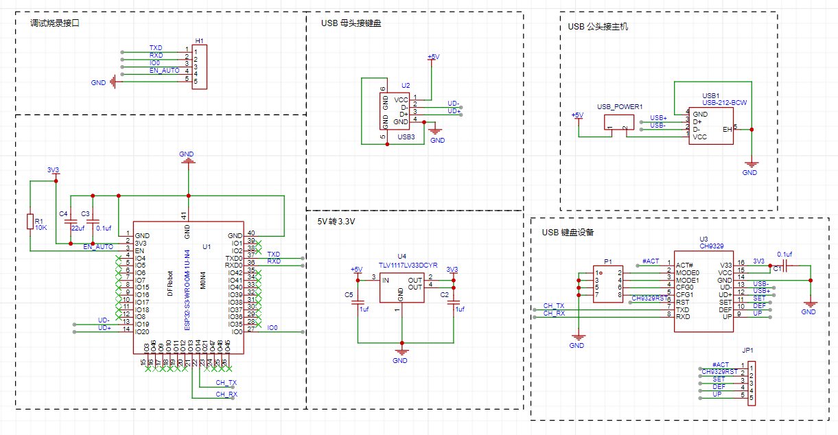
The upper left corner is a reserved debugging and programming interface, through which you can program the device and send debug information to the PC.
The lower left corner is the core of this design, an ESP32-S3 chip, which enables USB host and Bluetooth communication.
The ESP32-S3 operates at 3.3V, and a TLV1117 is used here. This chip only requires two 1uf capacitors.
The lower right corner is the CH9329 chip, an HID to serial port chip used in this design to implement the USB keyboard function.
The CH9326 is a driverless HID to serial port chip. The CH9326 supports bidirectional data transmission, used to receive serial port data and, according to the HID class device specification, package the data and upload it to the computer via USB, or receive USB data packets compliant with HID class devices from the computer and send them via serial port. The provided host computer software allows users to configure the chip's VID, PID, and various string descriptors. The chip is in an SOP16 package, making it easy to solder.
The basic design idea is that the ESP32-S3 parses USB keyboard data to obtain key information. This information is then sent to the CH9326 via serial port, and the CH9326 simulates key presses on the PC. As you can see, this device is transparent to the PC. Afterwards, the Blinker's Bluetooth function can be used to connect the phone and this device, allowing characters to be sent from the phone to the PC.
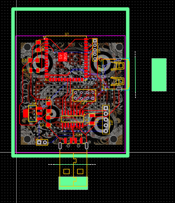
The PCB design is as follows:
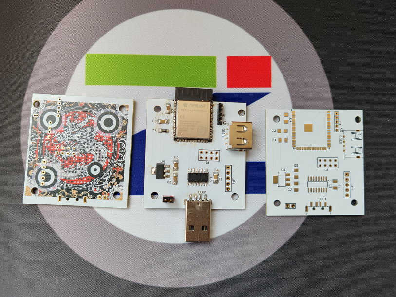
The finished product is as follows (color silkscreen printing, gold plating process, and a QR code on the back):
The Arduino code is as follows:
#include
#include
#include "show_desc.hpp"
#include "usbhhelp.hpp"
#define BLINKER_PRINT Serial
#define BLINKER_BLE
#include
//Keyboard data
char keypress[] = {0x57, 0xAB, 0x00, 0x02, 0x08, 0x00, 0x00, 0x00, 0x00, 0x00, 0x00, 0x00, 0x10};
bool isKeyboard = false;
bool isKeyboardReady = false;
uint8_t KeyboardInterval;
bool isKeyboardPolling = false;
elapsedMillis KeyboardTimer;
const size_t KEYBOARD_IN_BUFFER_SIZE = 8;
usb_transfer_t *KeyboardIn = NULL;
// Send the content pointed to by Buffer, length of size, and checksum to Serial2
void SendData(byte *Buffer, byte size) {
byte sum = 0;
for (int i = 0; i
Serial2.write(*Buffer);
sum = sum + *Buffer;
Buffer++;
}
*Buffer = sum;
Serial2.write(sum);
}
// Convert ASCII characters to HID Scancode values
byte Asc2Scancode(byte Asc, boolean *shift) {
if ((Asc >= 'a') && (Asc *shift = false; return (Asc - 'a' + 0x04); } if ((Asc >= 'A') && (Asc
*shift = true;
return (Asc - 'A' + 0x04);
}
if ((Asc >= '1') && (Asc
*shift = false;
return (Asc - '0' + 0x04);
}
if ((Asc >= '1') && (Asc
*shift = false;
return (Asc - '0' + 0x04); } 0x1E);
}
if (Asc == '>') {
*shift = true;
return (0x37);
}
if (Asc == '.') {
*shift = false;
return (0x37);
}
if (Asc == '_') {
*shift = true;
return (0x2D);
}
if (Asc == '-') {
*shift = false;
return (0x2D);
}
return 0;
}
// If an unbound component is triggered, its contents will be executed
// Input from input boxes will be handled here
void dataRead(const String & data)
{
BLINKER_LOG("Blinker readString: ",data);
boolean shift;
byte scanCode;
for (int i = 0; i
BLINKER_LOG("Key In", data.charAt(1));
// Convert the received ASCII to ScanCode
scanCode = Asc2Scancode(data.charAt(i), &shift);
// Some keys will be escaped when Shift is pressed
if (scanCode != 0) {
if (shift == true) {
keypress[5] = 0x02;
}
BLINKER_LOG("Scancode", scanCode);
// Fill in the ScanCode to be sent
keypress[7] = scanCode;
SendData((byte*)keypress, sizeof(keypress));
delay(10);
keypress[5] = 0x00; keypress[7] = 0;
SendData((byte*)keypress, sizeof(keypress));
delay(10);
}
}
}
void keyboard_transfer_cb(usb_transfer_t *transfer)
{
if (Device_Handle == transfer->device_handle) {
isKeyboardPolling = false;
if (transfer->status == 0) {
if (transfer->actual_num_bytes == 8) {
uint8_t *const p = transfer->data_buffer;
ESP_LOGI("", "HID report: %02x %02x %02x %02x %02x %02x %02x %02x",
p[0], p[1], p[2], p[3], p[4], p[5], p[6], p[7]);
// USB Host parses the data and transfers it to PC
//
memcpy(&keypress[5],p,transfer->actual_num_bytes);
SendData((byte*)keypress, sizeof(keypress));
}
else {
ESP_LOGI("", "Keyboard boot hid transfer too short or long");
}
}
else {
ESP_LOGI("", "transfer->status %d", transfer->status);
}
}
}
void check_interface_desc_boot_keyboard(const void *p)
{
const usb_intf_desc_t *intf = (const usb_intf_desc_t *)p;
if ((intf->bInterfaceClass == USB_CLASS_HID) &&
(intf->bInterfaceSubClass == 1) &&
(intf->bInterfaceProtocol == 1)) {
isKeyboard = true;
ESP_LOGI("", "Claiming a boot keyboard!");
esp_err_t err = usb_host_interface_claim(Client_Handle, Device_Handle,
intf->bInterfaceNumber, intf->bAlternateSetting);
if (err != ESP_OK) ESP_LOGI("", "usb_host_interface_claim failed: %x", err);
}
}
void prepare_endpoint(const void *p)
{
const usb_ep_desc_t *endpoint = (const usb_ep_desc_t *)p;
esp_err_t err;
// must be interrupt for HID
if ((endpoint->bmAttributes & USB_BM_ATTRIBUTES_XFERTYPE_MASK) != USB_BM_ATTRIBUTES_XFER_INT) {
ESP_LOGI("", "Not interrupt endpoint: 0x%02x", endpoint->bmAttributes);
return;
}
if (endpoint->bEndpointAddress & USB_B_ENDPOINT_ADDRESS_EP_DIR_MASK) {
err = usb_host_transfer_alloc(KEYBOARD_IN_BUFFER_SIZE, 0, &KeyboardIn);
if (err != ESP_OK) {
KeyboardIn = NULL;
ESP_LOGI("", "usb_host_transfer_alloc In fail: %x", err);
return;
}
KeyboardIn->device_handle = Device_Handle;
KeyboardIn->bEndpointAddress = endpoint->bEndpointAddress;
KeyboardIn->callback = keyboard_transfer_cb;
KeyboardIn->context = NULL;
isKeyboardReady = true;
KeyboardInterval = endpoint->bInterval;
ESP_LOGI("", "USB boot keyboard ready");
}
else {
ESP_LOGI("", "Ignoring interrupt Out endpoint");
}
}
void show_config_desc_full(const usb_config_desc_t *config_desc)
{
// Full decode of config desc.
const uint8_t *p = &config_desc->val[0];
static uint8_t USB_Class = 0;
uint8_t bLength;
for (int i = 0; i wTotalLength; i += bLength, p += bLength) {
bLength = *p;
if ((i + bLength) wTotalLength) {
const uint8_t bDescriptorType = *(p + 1);
switch (bDescriptorType) {
case USB_B_DESCRIPTOR_TYPE_DEVICE:
ESP_LOGI("", "USB Device Descriptor should not appear in config");
break;
case USB_B_DESCRIPTOR_TYPE_CONFIGURATION:
show_config_desc(p);
break;
case If
(isKeyboard && KeyboardIn == NULL) prepare_endpoint(p);
break;
case USB_B_DESCRIPTOR_TYPE_DEVICE_QUALIFIER:
// Should not be config config?
ESP_LOGI("", "USB device qual desc TBD");
break;
case USB_B_DESCRIPTOR_TYPE_OTHER_SPEED_CONFIGURATION:
// Should not be config config?
ESP_LOGI("", "USB Other Speed TBD");
break;
case USB_B_DESCRIPTOR_TYPE_INTERFACE_POWER:
// Should not be config config?
ESP_LOGI("", "USB Interface Power TBD");
break;
case 0x21:
if (USB_Class == USB_CLASS_HID) {
show_hid_desc(p);
}
break;
default:
ESP_LOGI("", "Unknown USB Descriptor Type: 0x%x", bDescriptorType);
break;
}
}
else {
ESP_LOGI("", "USB Descriptor invalid");
return;
}
}
}
void setup()
{
// Initialize debug serial port
Serial.begin(115200);
// Initialize CH9329 serial port
Serial2.begin(9600, SERIAL_8N1, 14, 13, false, 1000, 112);
//Serial2.begin(9600);
#if defined(BLINKER_PRINT)
BLINKER_DEBUG.stream(BLINKER_PRINT);
#endif
// Initialize blinker
Blinker.begin();
Blinker.attachData(dataRead);
usbh_setup(show_config_desc_full);
}
void loop()
{
usbh_task();
Blinker.run();
if (isKeyboardReady && !isKeyboardPolling && (KeyboardTimer > KeyboardInterval)) {
KeyboardIn->num_bytes = 8;
esp_err_t err = usb_host_transfer_submit(KeyboardIn);
if (err != ESP_OK) {
ESP_LOGI("", "usb_host_transfer_submit In fail: %x", err);
}
isKeyboardPolling = true;
KeyboardTimer = 0;
}
while (Serial.available()) {
char c = Serial.read();
if (c == 'q') {
boolean shift = false;
// Fill in the ScanCode to be sent
keypress[5] = 0x08;
SendData((byte*)keypress, sizeof(keypress));
delay(20);
keypress[5] = 0;
SendData((byte*)keypress, sizeof(keypress));
}
Serial.print(c);
}
}
Photo of the board after it has been installed in the casing:

USB Keyboard Prank Master~1.mp4
USBKBChaos.ino
PDF_USB Keyboard Prankster.zip
Altium_USB Keyboard Prankster.zip
PADS_USB Keyboard Prankster.zip
BOM_USB Keyboard Prankster.xlsx
91337
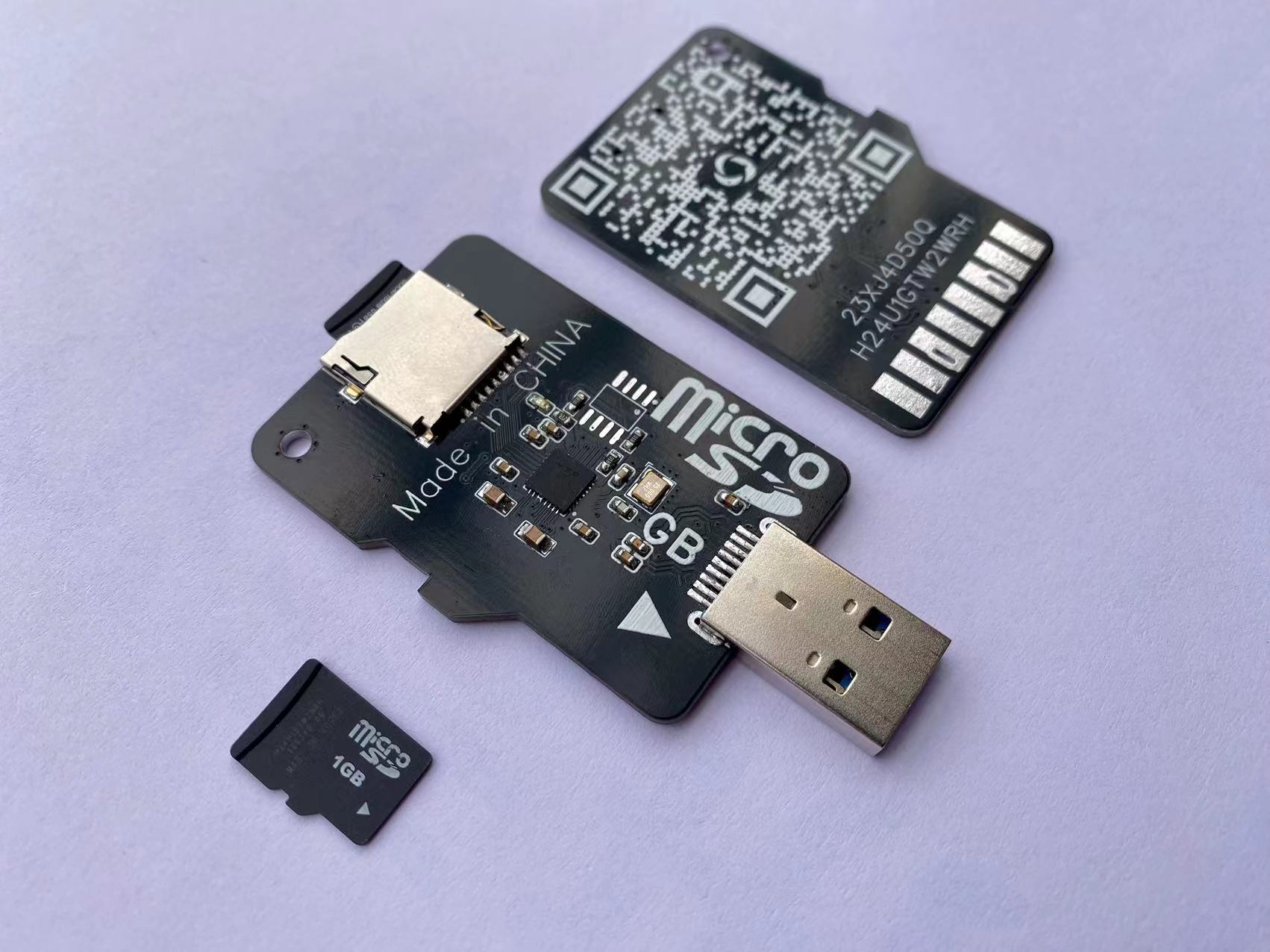
USB 3.0 TF card reader, based on GL3224 solution.
USB 3.0 TF card reader based on GL3224 [Verified]
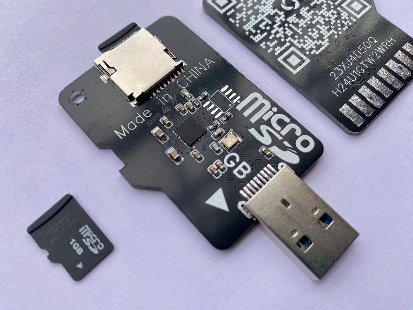
Same formula, different implementation.
Bilibili video introduction: --> Click to go.
Many users have messaged me asking for a version that only includes a TF card slot.
This time, I designed a skeuomorphic style, which looks quite aesthetically pleasing overall.
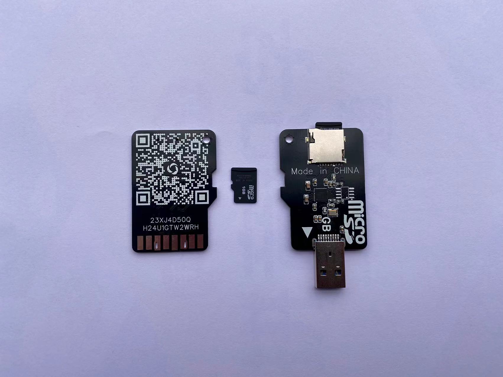
This chip requires firmware upgrade to 1536 to use USB 3.0.
To upgrade to a higher firmware version, a flash chip must be soldered.
For specific update methods and software packages, refer to the previous open-source project.
↓ ↓ ↓ ↓ ↓
USB 3.0 card reader, based on the GL3224 solution,
provides two version options:
1. Normal version
; 2. Version with write protection switch. Firmware
upgrade------
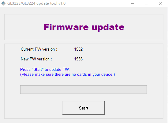
Upgrading the GL3224 firmware to 1536 requires an external flash chip.
You can use GL3224 update tool v1.0 for the upgrade. For
software upgrades, please check if the software supports the flash chip.
If not, please modify the software's config.ini file.
For detailed tutorials, refer to here:
Firmware Upgrade .
Static Display.mp4
GL3224 update tool v1.0.zip
PDF_USB3.0 TF Card Reader, based on GL3224 solution.zip
Altium_USB3.0 TF card reader, based on GL3224 solution.zip
PADS_USB3.0 TF card reader, based on GL3224 solution.zip
A TF card reader with BOM (USB 3.0) based on the GL3224 solution.xlsx
91338
A Winter-Warm Creation: Light Painting
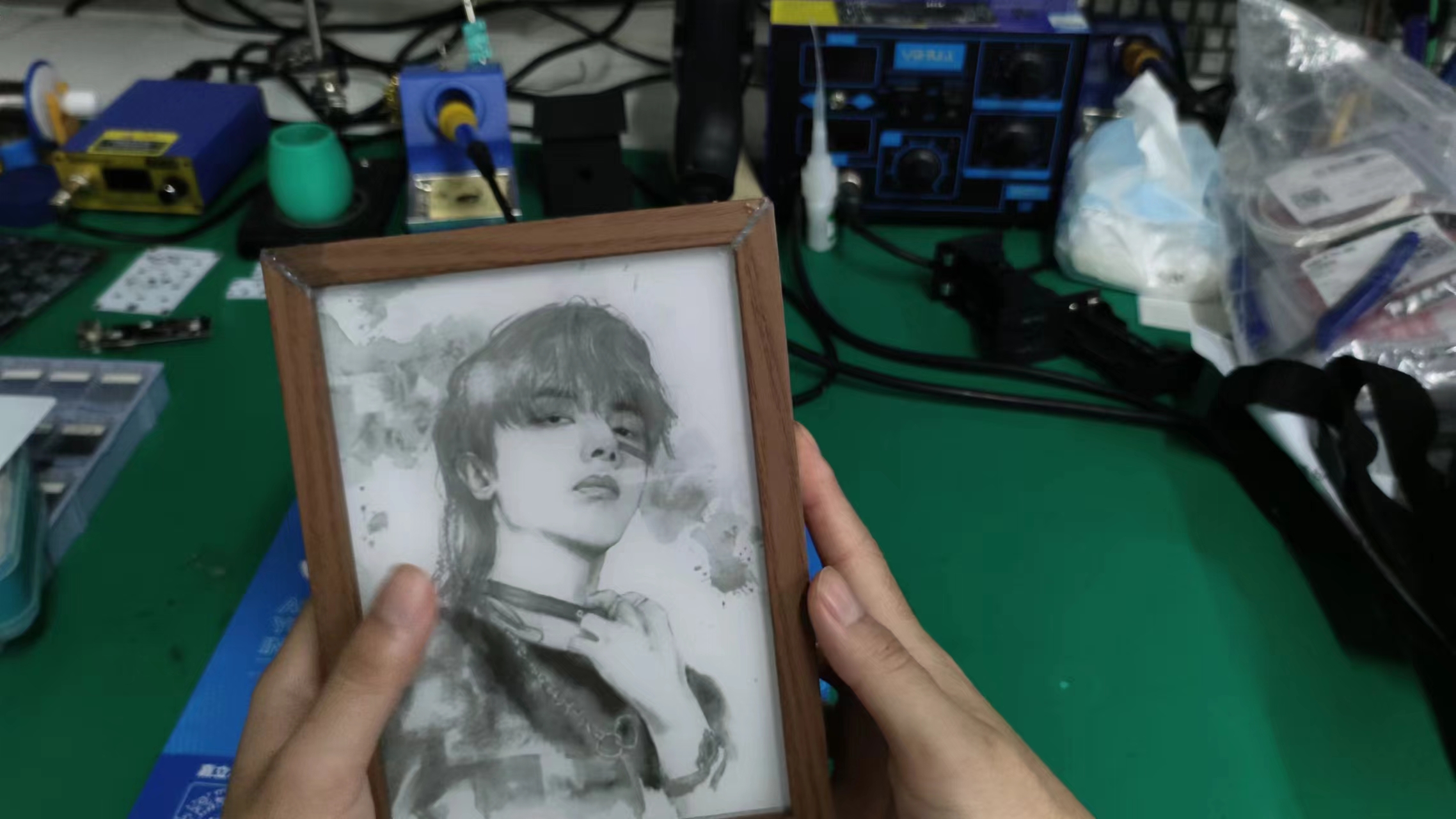
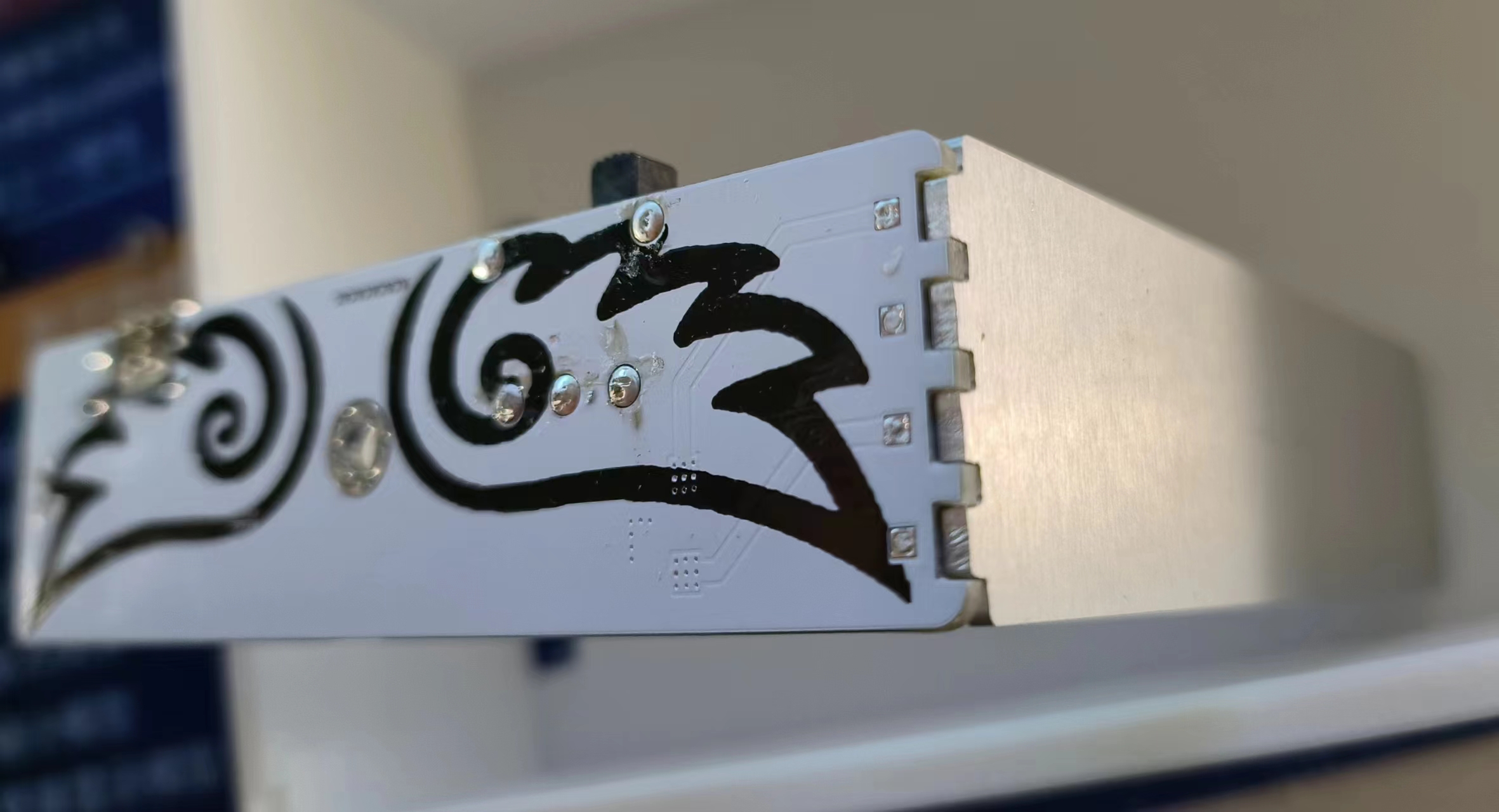
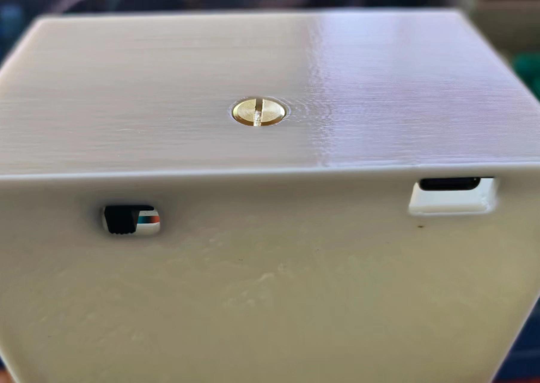
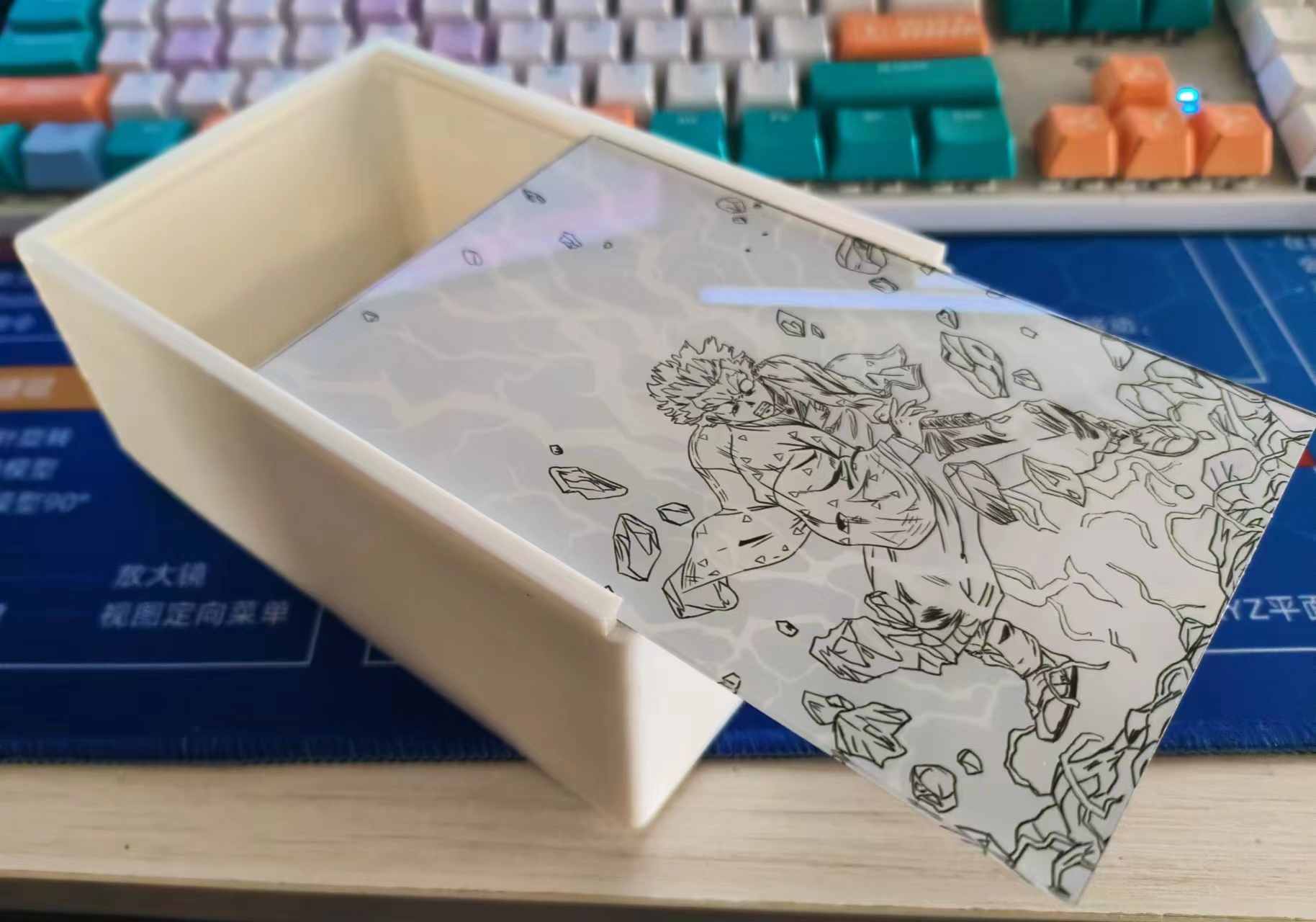
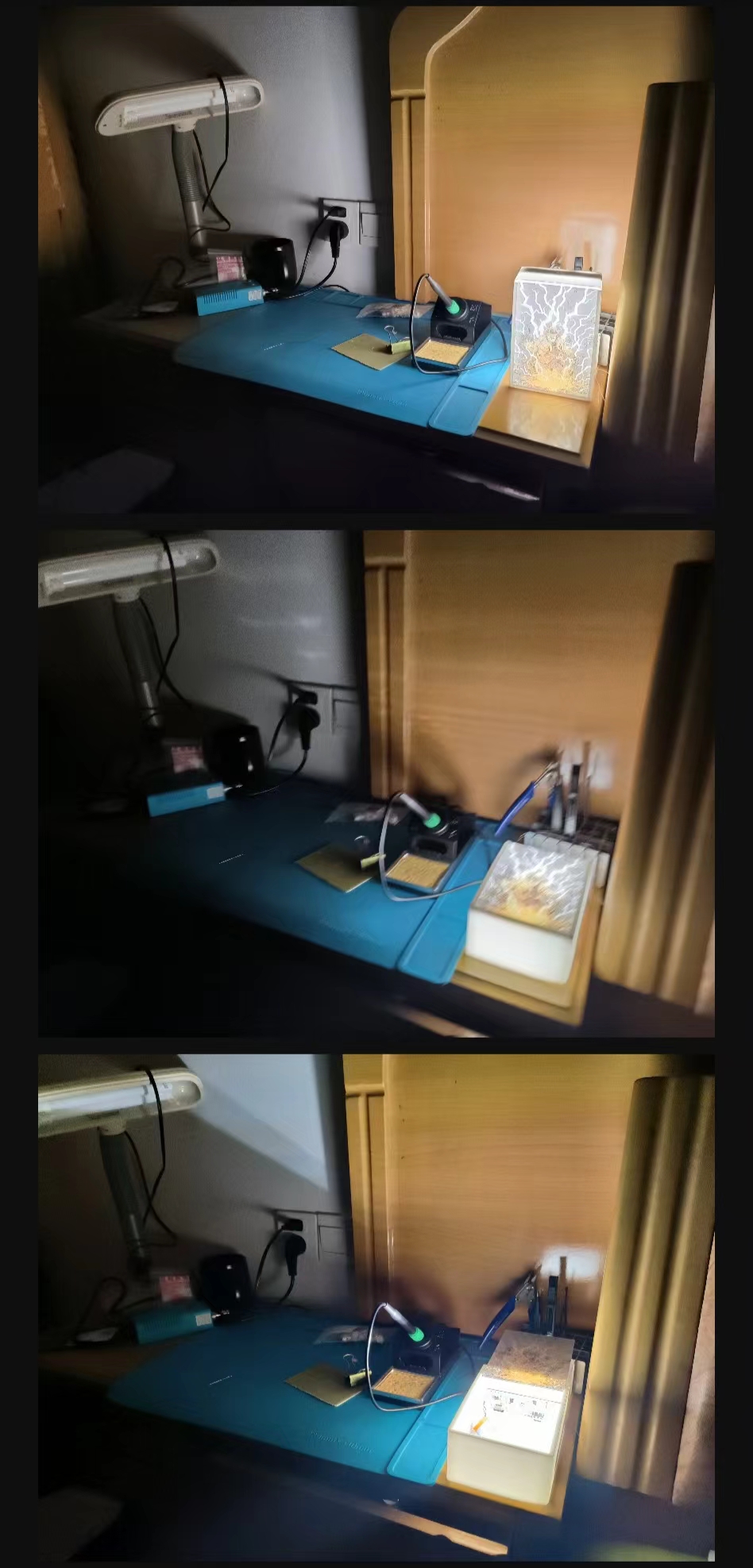
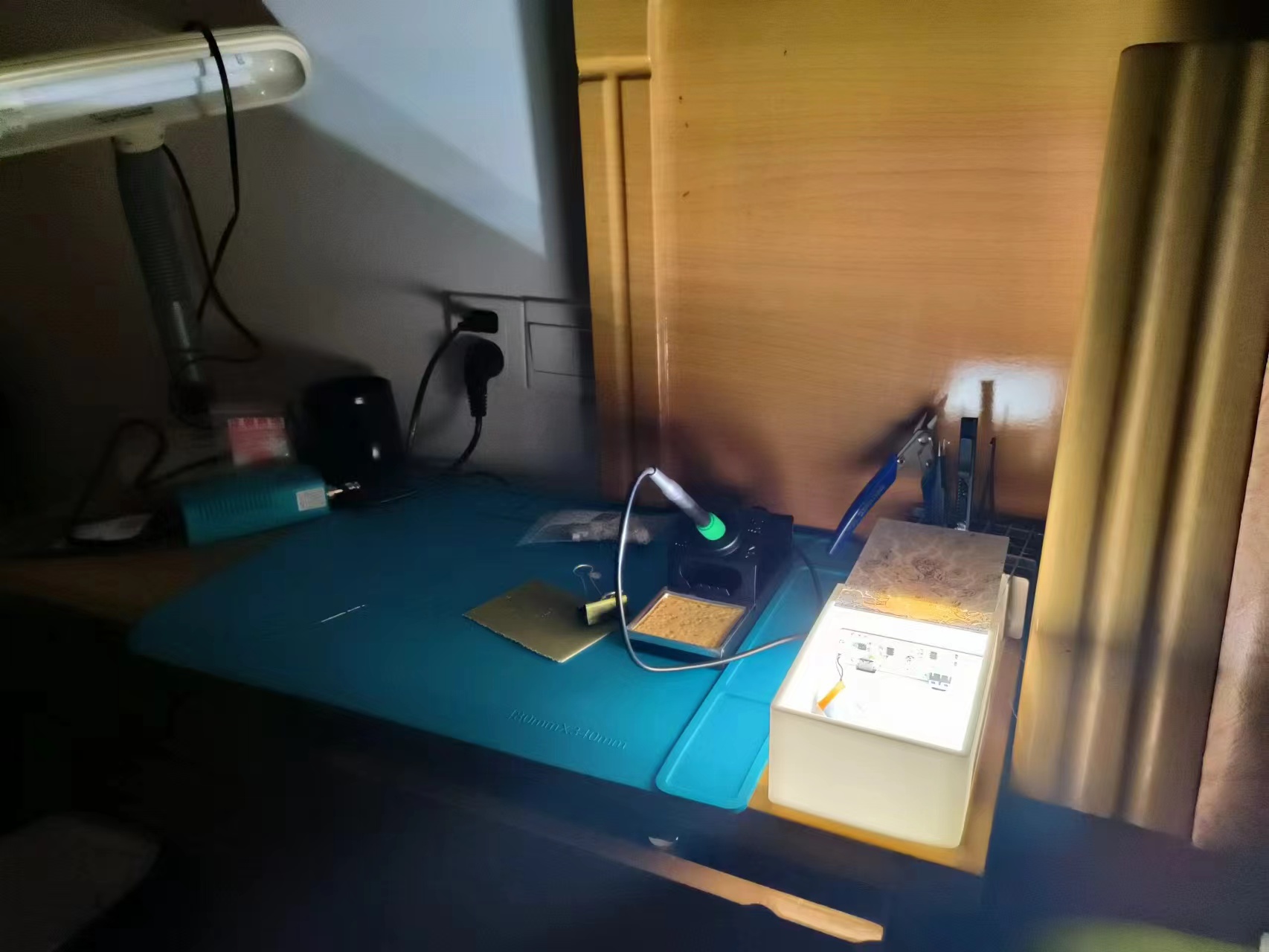
This light painting project includes a three-level stepless dimming touch light main control board design, a high-heat-dissipation aluminum-based light board design, an acrylic panel design, and a 3D shell modeling. The main circuit can be matched with a 7-inch wooden picture frame and a 6-inch 3D shell.
A Winter-Warm Creation: Light Painting.
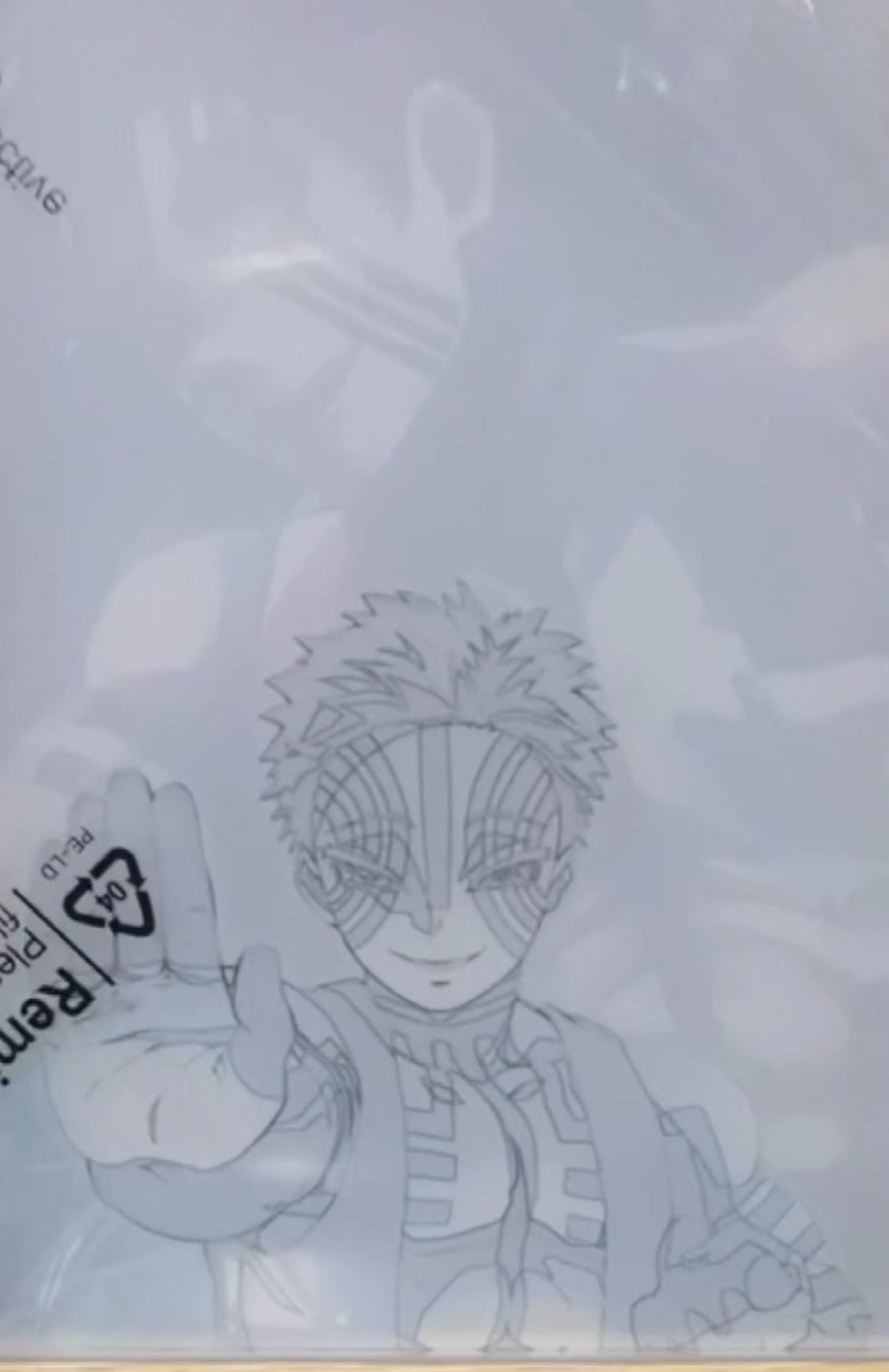
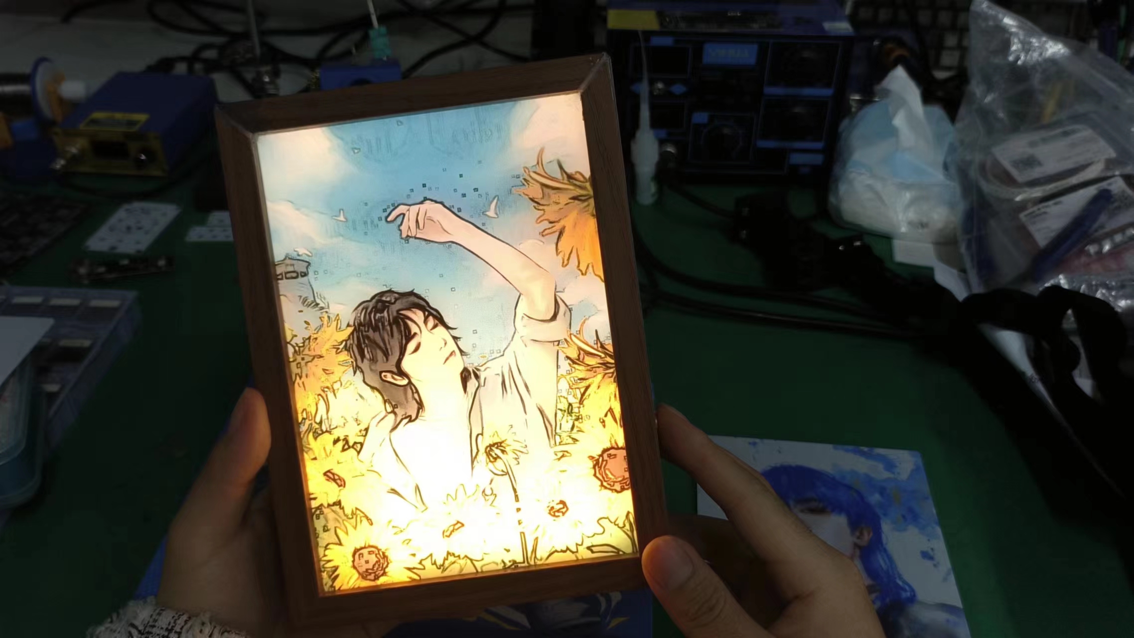
First, let's look at two effect images
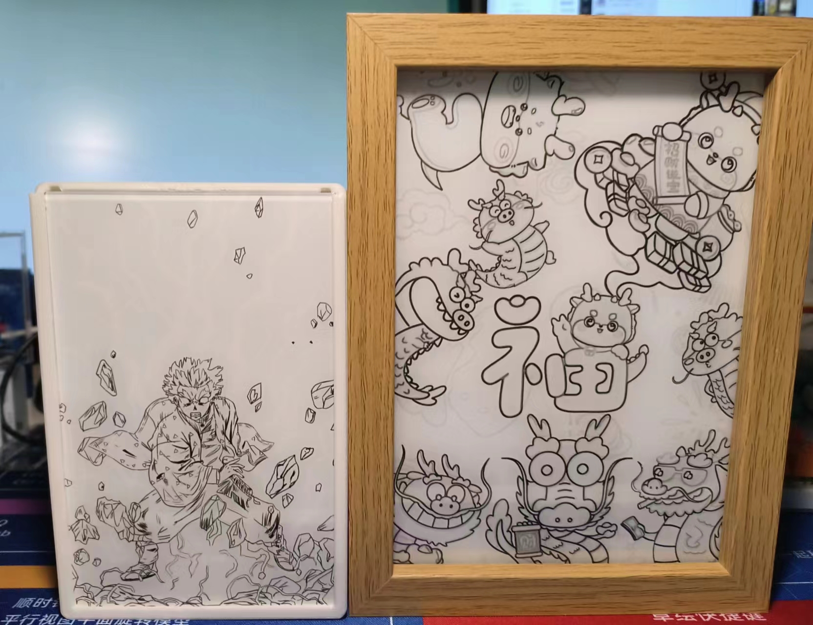
(without lights) and
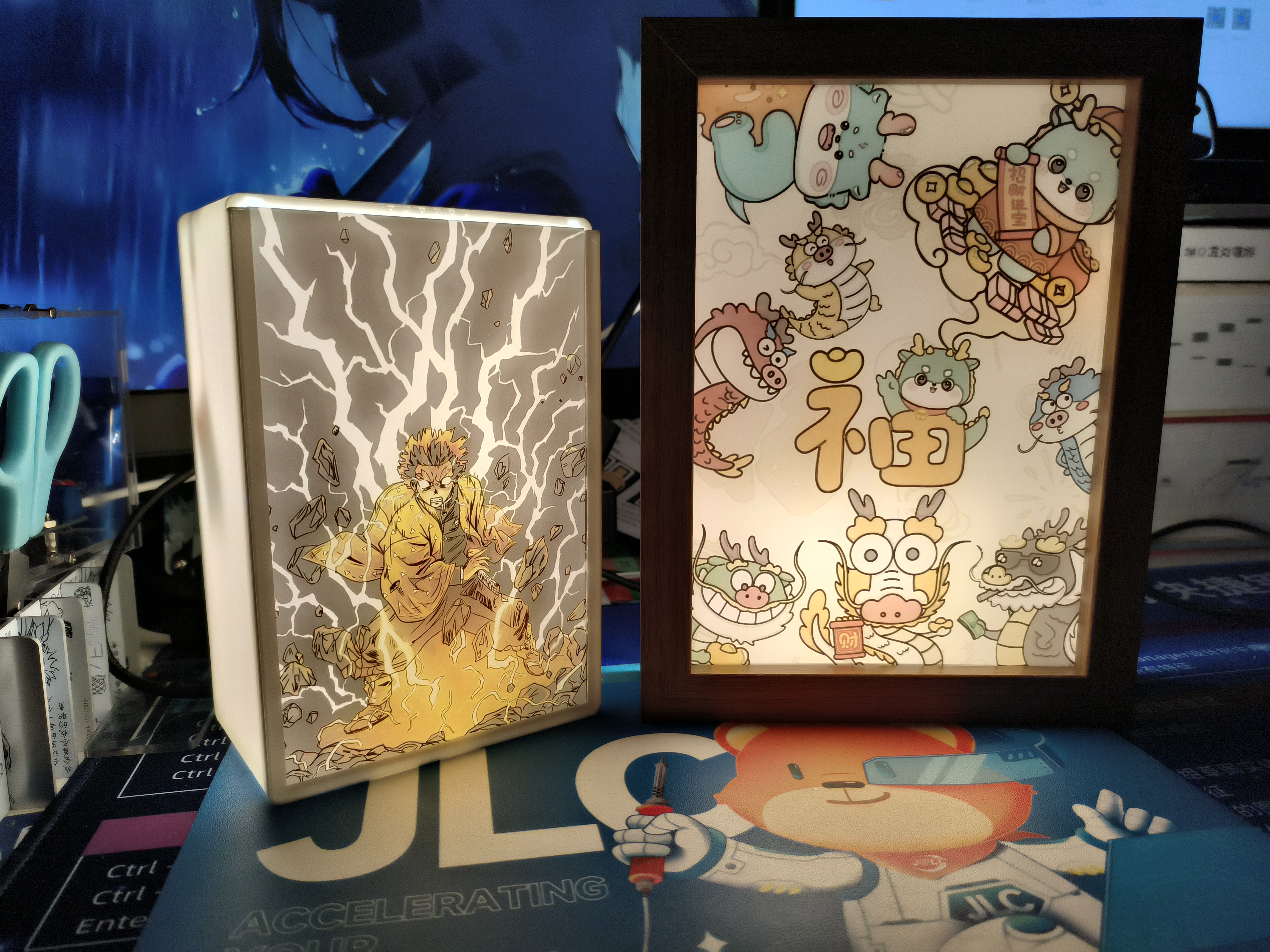
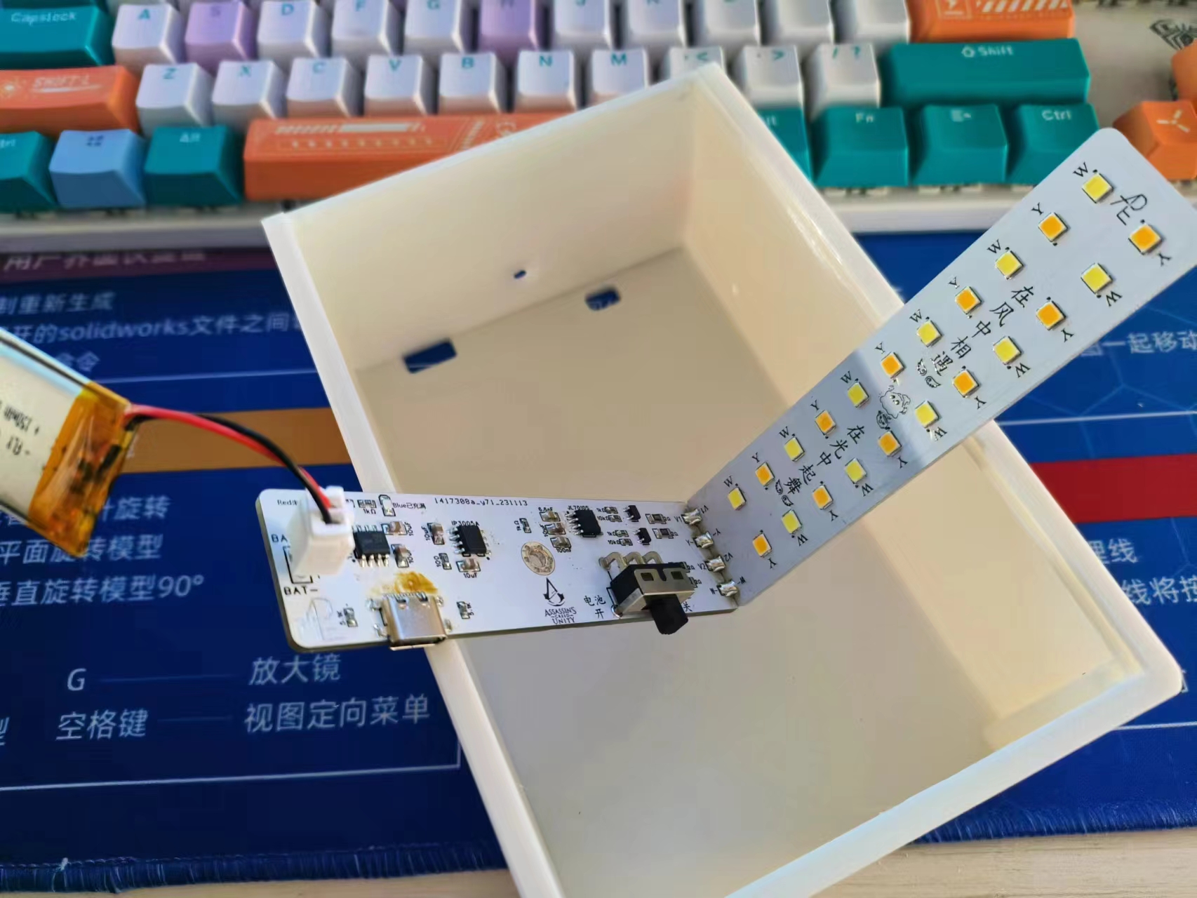
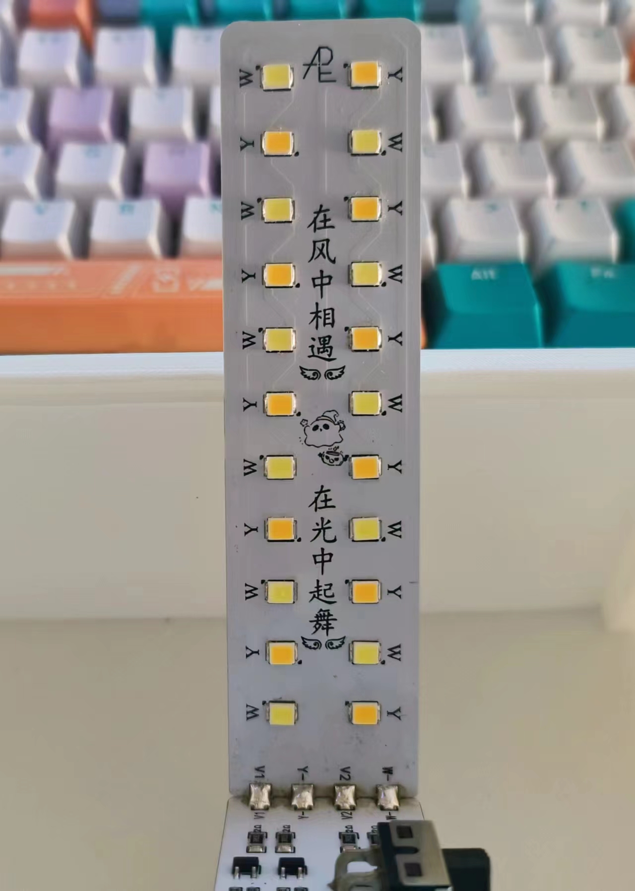
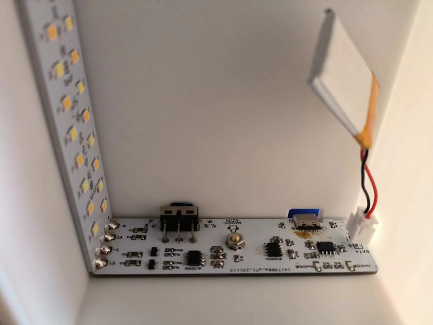
(with lights). Circuitry
: This circuit can switch between TYP-C power supply and lithium battery power supply
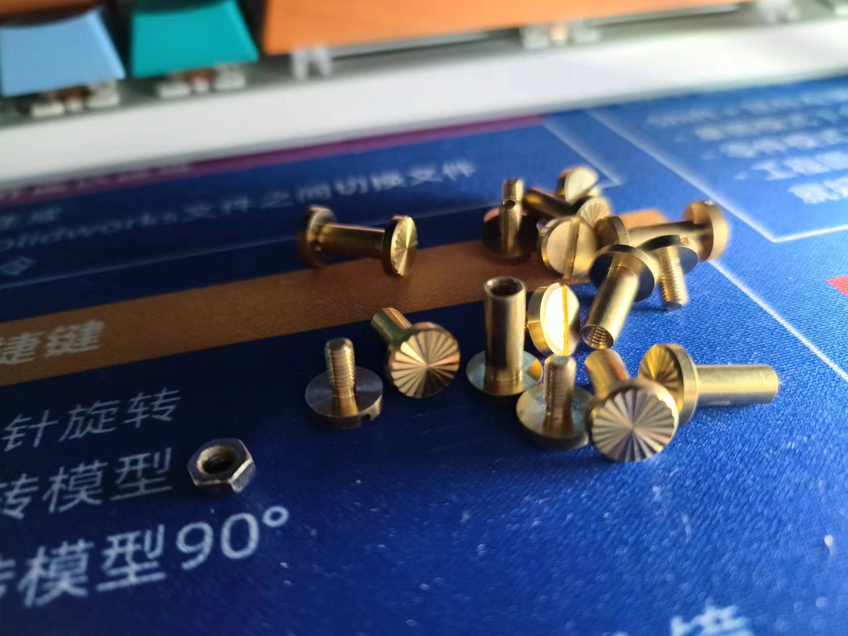
using a toggle switch. It uses a copper pillar touch switch and has three light levels: white light, warm light, and mixed natural light. A light
tap switches the light, and a long press adjusts the brightness (the lithium battery discharge time depends on the capacity of the lithium battery used).
How about that? Isn't it amazing? (´。✪ω✪。`)
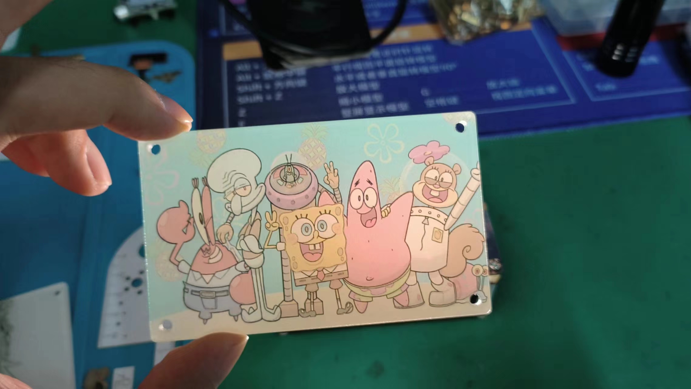
Without the lights, it's a black and white line drawing; with the lights on, it becomes a color picture.
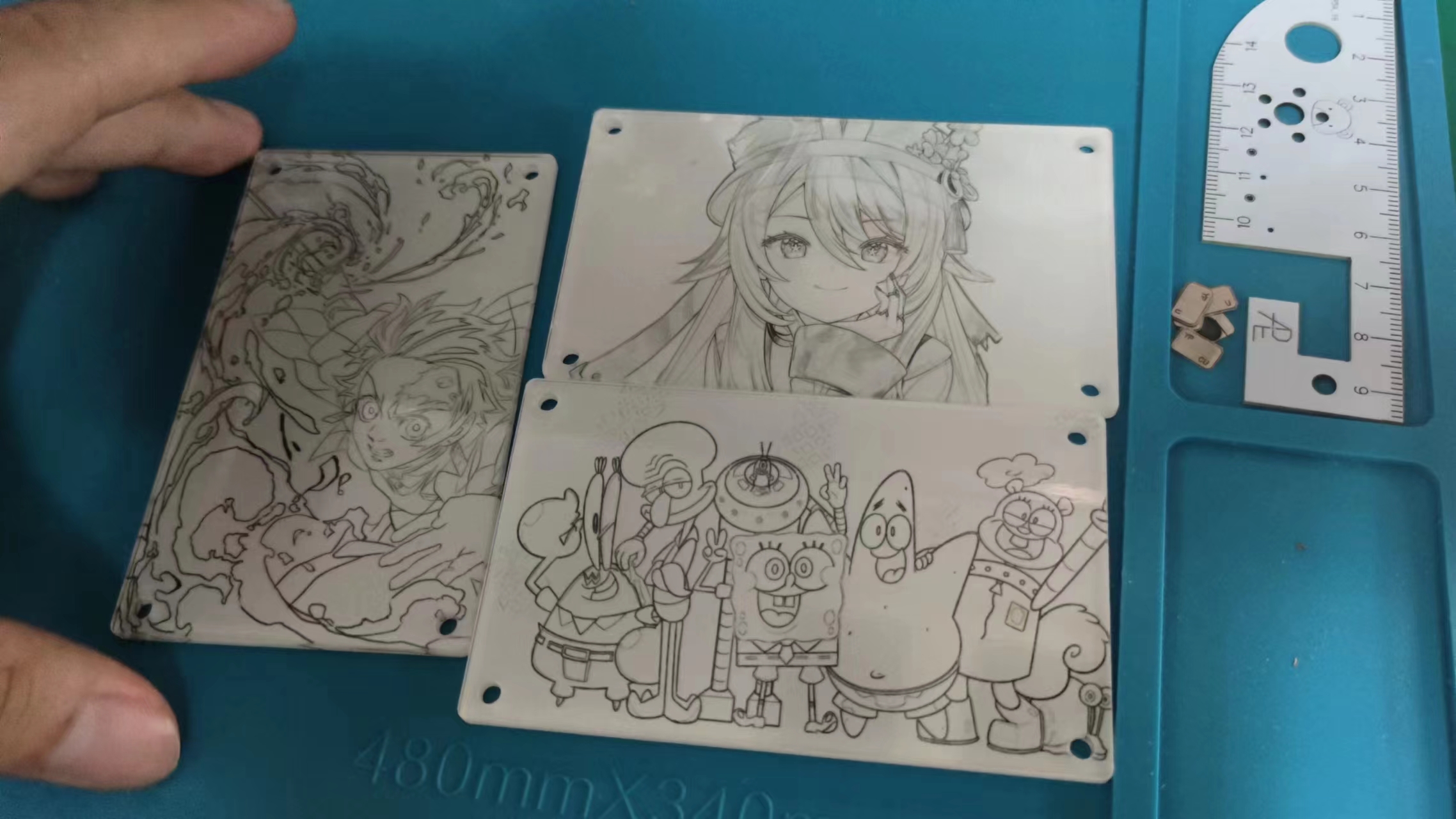
When light painting became popular, I really disliked the laminated structure using A4 paper and film.
Since I frequently used LCSC panels for printing, I wondered if it could be simpler to use a single acrylic sheet for printing
, making assembly easier and improving the texture. After studying the optical principles behind light painting, I discovered that only three layers were needed to achieve this effect . The first and third layers
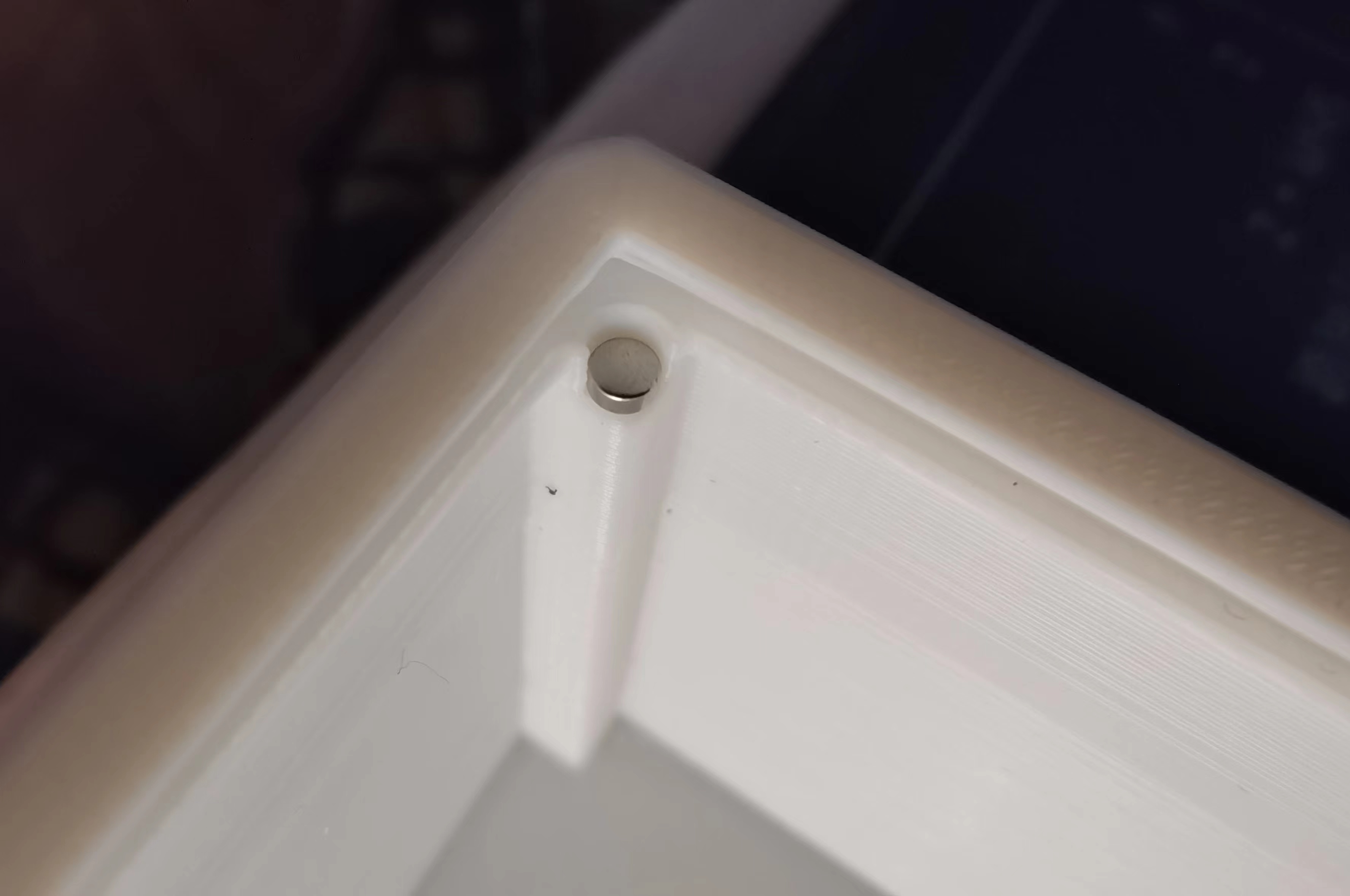
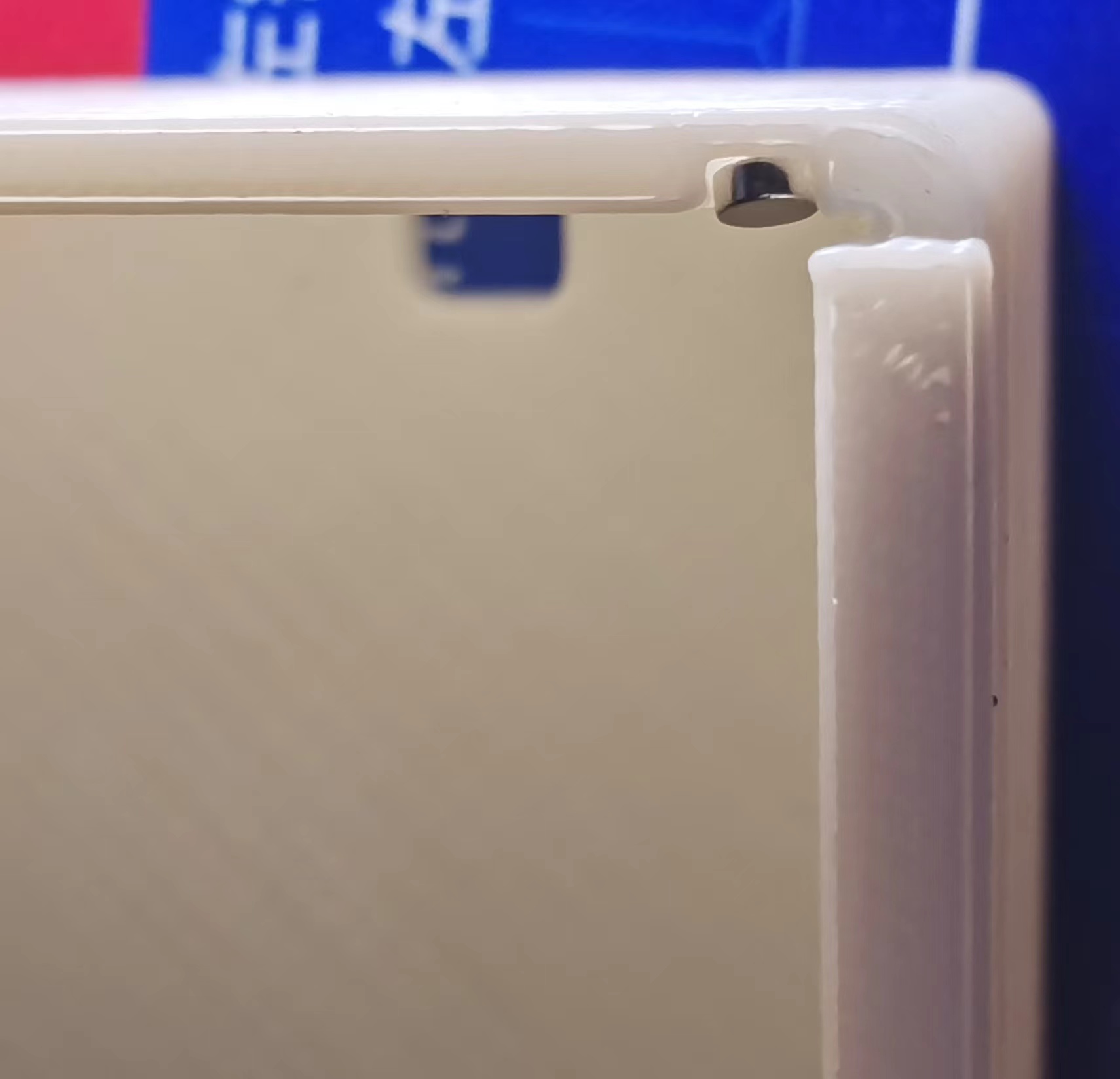
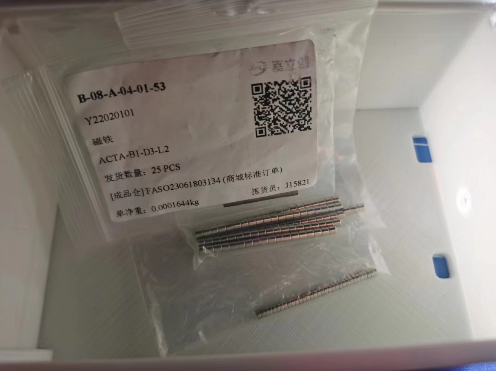
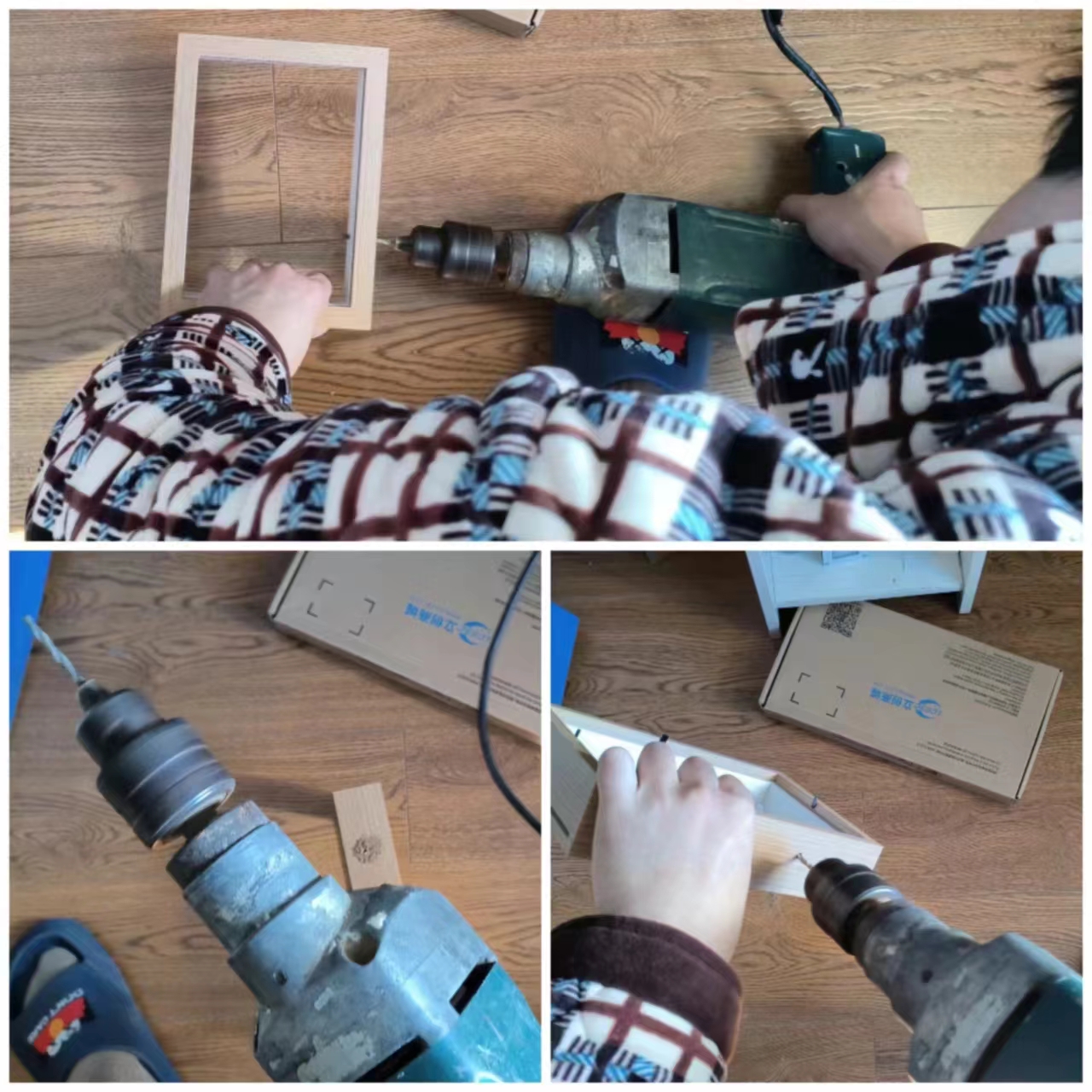
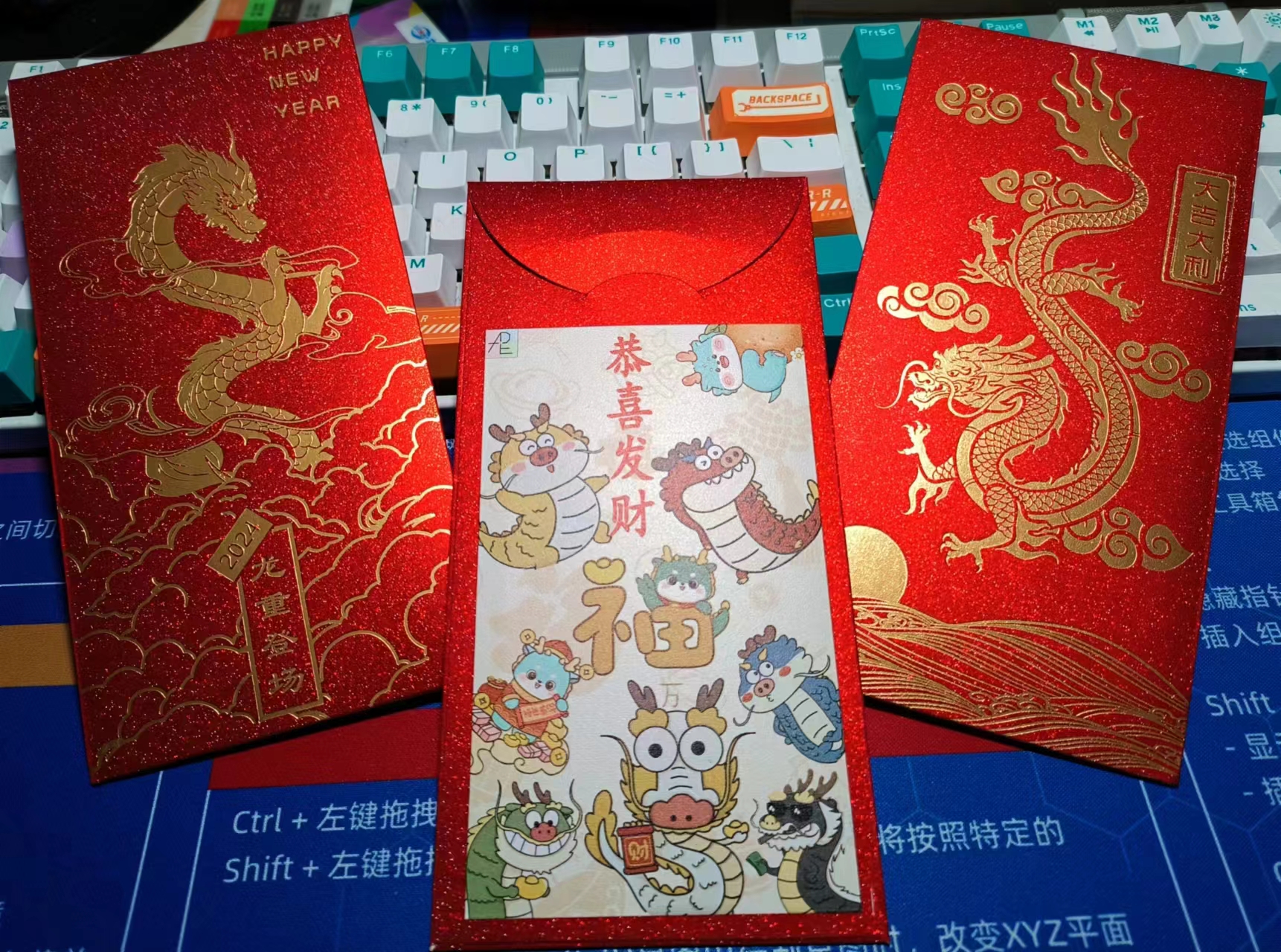
could be printed normally; the key was the second layer . I tested the second layer on the LCSC panel with 0%, 10%, 20%, and 30% opacity. I found that 20% opacity produced the best effect; the colors wouldn't show through without the light, and with the light on, the colors showed good light transmission. My first test was a disaster; I overthought it and printed a five-layer laminate structure on the LCSC panel. The overall appearance was poor. The second test involved testing several small pieces, and the light transmission effect was excellent! (๑>) The third version involved making three 7-inch acrylic pieces. These were made in April, but I didn't know how to do the circuitry, so I put them aside because I really disliked the tri-color adjustable light strip that came with the picture frame, which required a USB connection. So I learned how to make lighting circuits, hoping to achieve better results. In the past six months, I've studied touch chip circuits, lithium battery charging circuits, charging protection circuits, optical principles, lamp board heat dissipation principles, 3D modeling, and material selection. I've also learned some Photoshop-related knowledge and skills, repeatedly reviewing various chip datasheets and calculating current and voltage repeatedly. I just love learning, and I love telling the truth. (「・ω・)「Hey, the circuit section (lithium battery - main control board - aluminum-based lamp board) is shown below. The lamp board and main control board are connected by a toothed, interlocking solder joint (a pin header slot is also provided for pin header connections). The 3D printed grooves are flawless, and the countersunk holes of the copper pillars are recessed, so they don't feel uncomfortable at all. They're assembled and secured with copper screws, which also function as touch switches. I think the sunflower screw is the best part of the material selection; it gives the touch switch a premium feel. When I was designing this 3D shell, I was really impressed by the sliding mechanism that comes with the JLCPCB EDA editor (๑•̀ㅂ•́)و✧. I thought, since there's so much space inside a picture frame, could we just make a sliding box and use the panel as the lid? It's practical and looks great! And here it is! There are 3mm magnet holes pre-drilled at the four corners inside the shell. In the next upgrade, we'll add magnet holes at the four corners of the panel so it won't be so easy to open. It has a resistance switch box effect, and when all the lights are off in the bedroom, it can be used as a bedside lamp! It won't hurt your eyes at all when playing on your phone at night. After talking about the 3D shell version, let's look at the picture frame version. This drill is too long and difficult to operate, and it's also loud QAQ. Because the picture frame needs to drill a hole to install the copper pillar of the touch switch, and the small electric drill I bought at school can't be taken home on the train, I had to use my dad's impact drill . The touch switch is very beautiful and fits perfectly. Originally, I wanted to use this picture as the main center for the warm winter creation (it looks very warm) , but how did you know I designed a red envelope (⑉°з°)-♡ I cut out each dragon in the whole picture one by one using Photoshop. I thought this photo fits the warm winter of the Year of the Dragon better ( •̀ ω •́ )y Then I made a few minor edits in Photoshop to create a black and white line drawing with a warm lighting effect. Let's watch the video! Bilibili video link 1: https://www.bilibili.com/video/BV1Pb4y1P7YA/?spm_id_from=333.999.0.0 Bilibili video link 2: https://www.bilibili.com/video/BV1iT4y1t7LY/?spm_id_from=333.999.0.0


PDF_Warm Winter Creations: Light Paintings.zip
Altium_Warm Winter Creations: Light Paintings.zip
PADS_Warm Winter Creations: Light Paintings.zip
BOM_Warm Winter Creations: Light Painting.xlsx
91339
LED headlights (simplified version)
Simplified LED headlight design, designed for easy replication
This project is modified from NUCL's "OneShot" LED light bulb project.
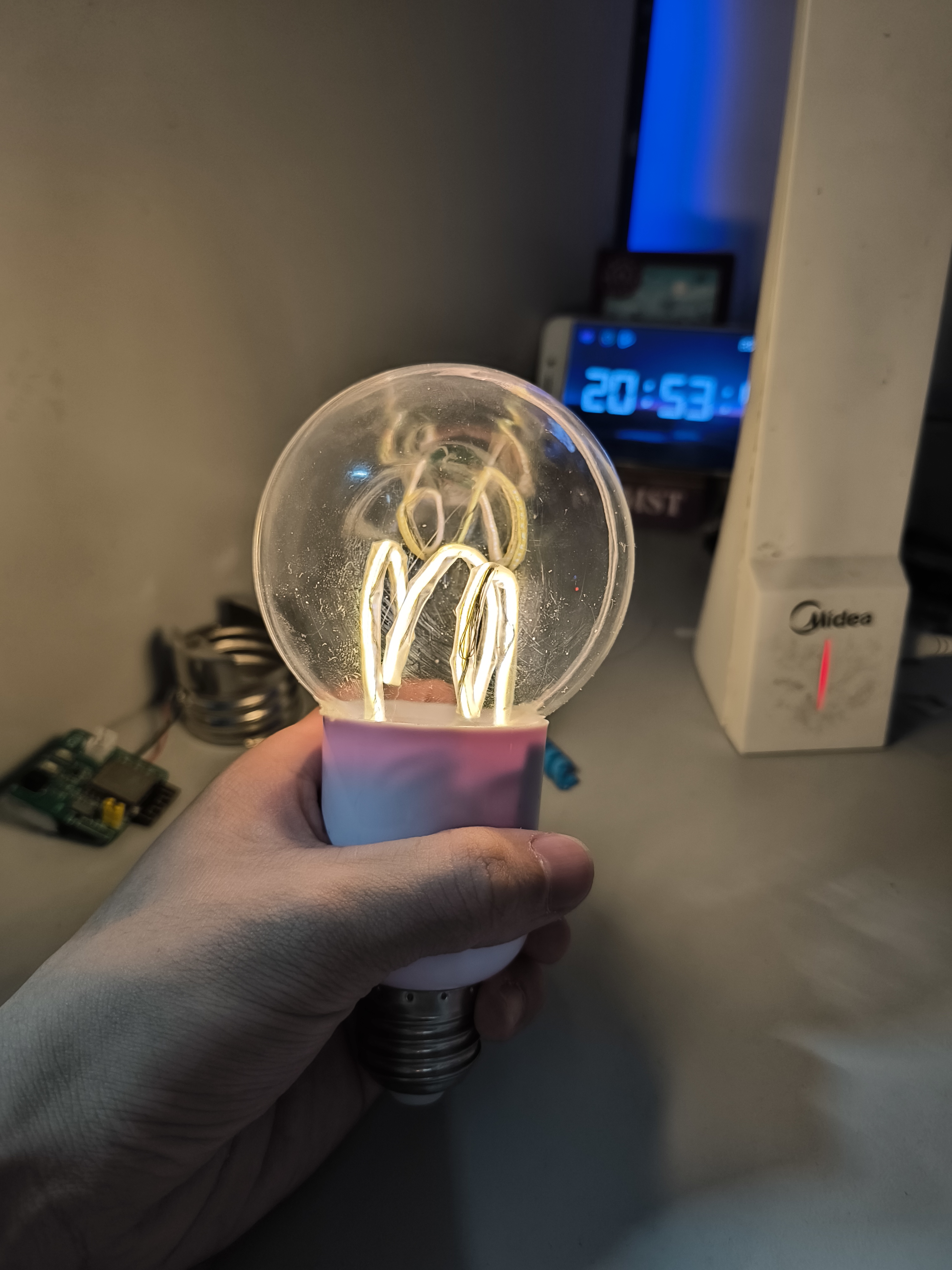
The story begins: It was a sunny day, and Xiao Li was casually slacking off at his workstation as usual. Suddenly, a large light bulb caught his eye. Xiao Li was instantly captivated by its appearance and effect. A closer look revealed a detailed tutorial. After a moment's thought, he quickly completed a feasibility analysis and decided to replicate it.
The story unfolds: By this time, Xiao Li had calmed down and carefully analyzed the situation. He realized he didn't have a 3D printer. How could he print the outer shell? Would he have to pay for it? The lampshade needed to be custom-made. What was Xiao Li, who was both socially awkward and poor, supposed to do? Giving up was out of the question; he had to find another way. After a night of technical scrambling (not really), he finally came up with a good solution.
The story concludes: Xiao Li successfully replicated the light bulb, earning praise and recognition from his colleagues. He was very pleased with himself. And so, he happily went back to slacking off. This
project
does not require: a 3D printer, a custom acrylic lampshade, or a radar sensor module.
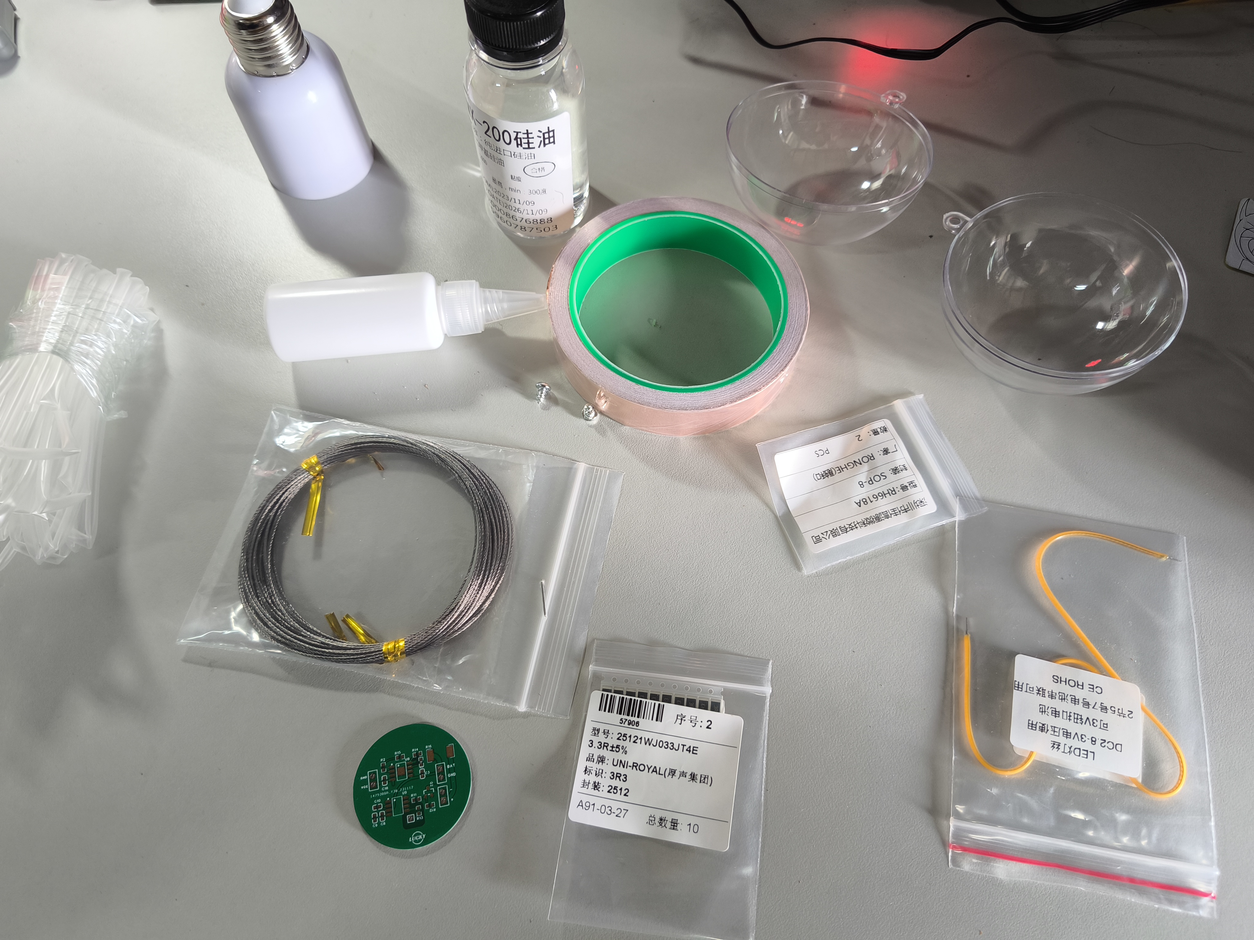
This project requires: an electric grinder.
Compared to the original project, the modifications are:
retaining the touch-activated and dimming functions, and removing the radar sensor function. (No debugging required, ready to use after soldering). A
common E27 to E40 converter lamp head is used instead of the 3D printed shell (priced at 3.5 yuan/each).
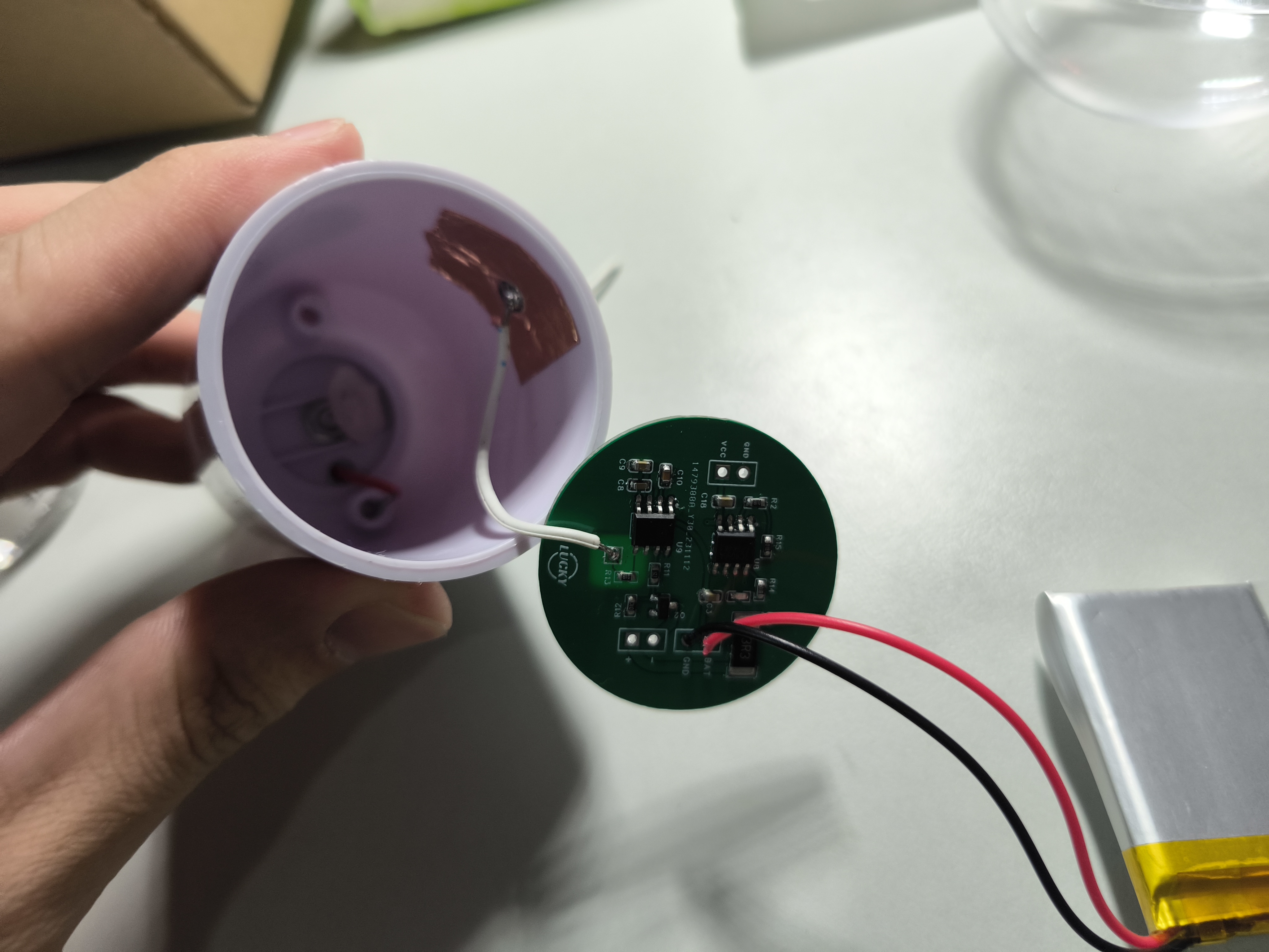
The lamp head's built-in metal connector is used with the E27 base for charging. The metal connector of the lamp head connects to the charging pins on the PCB. The E27 base requires a 5V input.
A common 8cm acrylic ball is used instead of the custom lampshade (the protrusion needs to be smoothed with an electric grinder, and a gap should be visible in the middle).
Note:
Hot melt adhesive is used to bond the lamp head and the acrylic ball. For
the filament's concave shape, you can try heating and shrinking the tubing with wire; the heat-shrink tubing will set after heating.
Some process pictures:

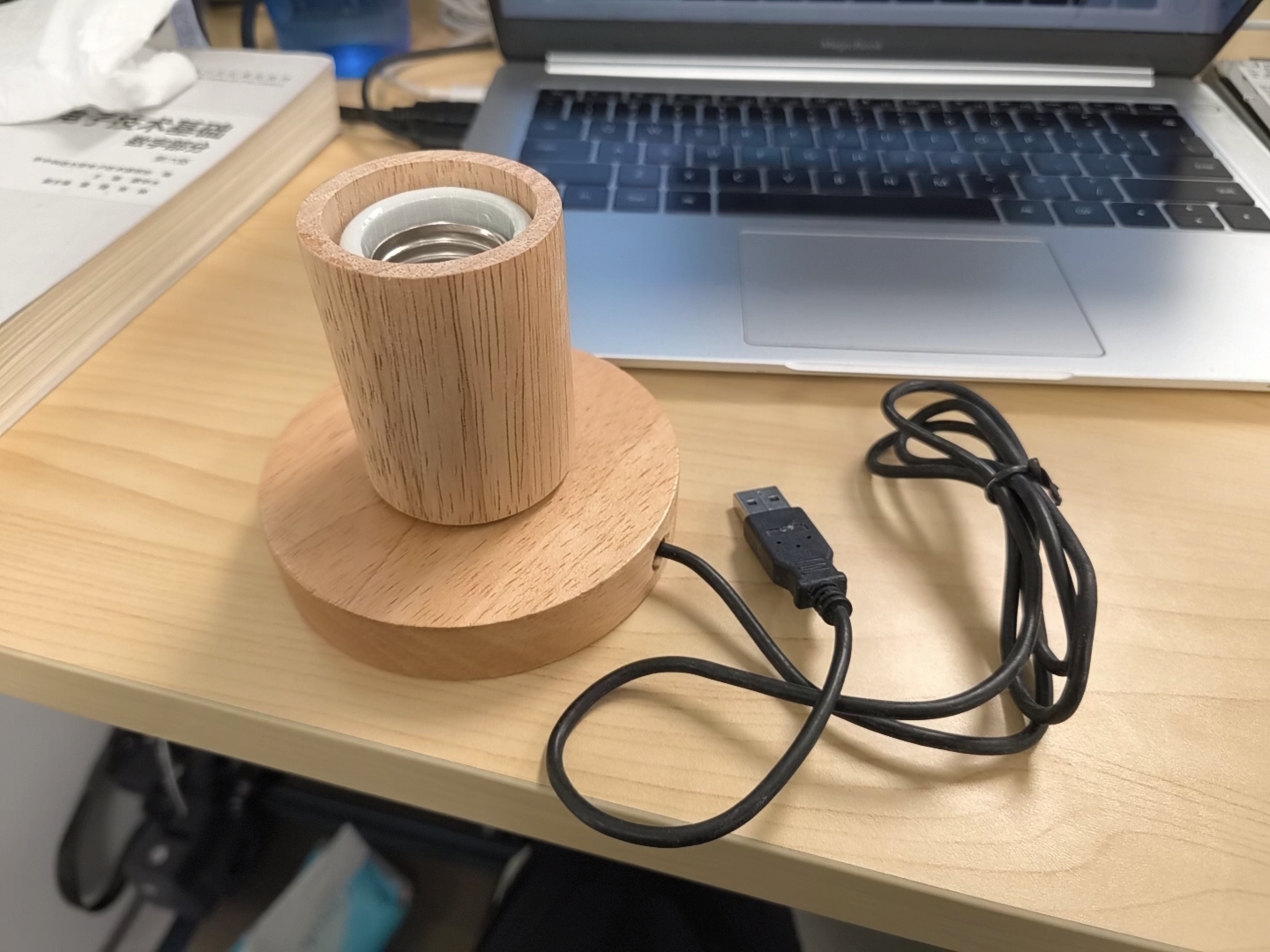
Lamp holder (this is more expensive; cheaper options are available):
PDF_LED Light Bulb (Simplified Version).zip
Altium LED Light Bulb (Simplified Version).zip
PADS_LED Light Bulb (Simplified Version).zip
BOM_LED Light Bulb (Simplified Version).xlsx
91340
electronic
 The finished product is as follows (color silkscreen printing, gold plating process, and a QR code on the back):


 京公网安备 11010802033920号

 GLYC3N910


