Project Description:
This project utilizes the air001 main control chip combined with the SR_FRS_2WUS wireless walkie-talkie module to create a simple walkie-talkie. The device supports 20 public walkie-talkie channels, sub-tone and scrambling functions, providing enhanced communication security. A CW2015 battery monitoring chip is used to monitor battery level in real time, ensuring stable operation over extended periods. Simultaneously, the AT24C02 chip enables power-off storage of parameter settings, ensuring user-defined parameters are not lost during power outages, improving user experience and convenience. The project is licensed under the GPL 3.0
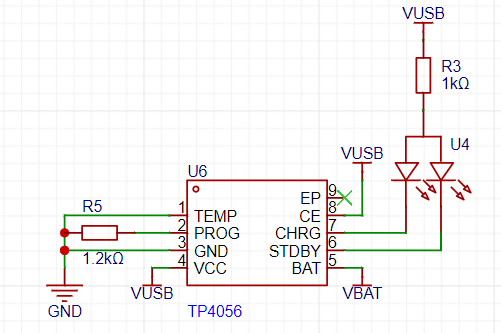
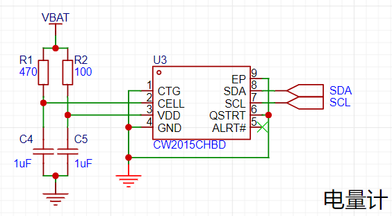
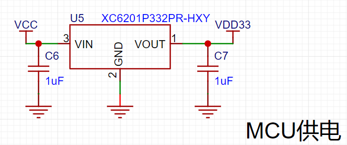
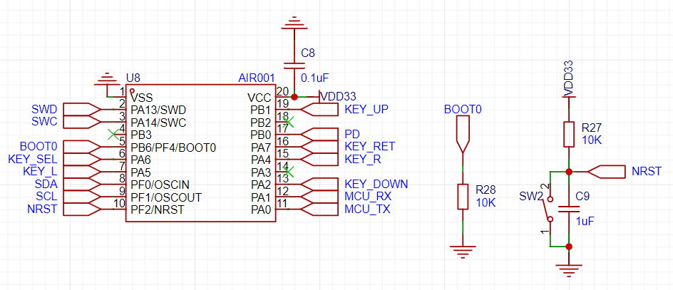
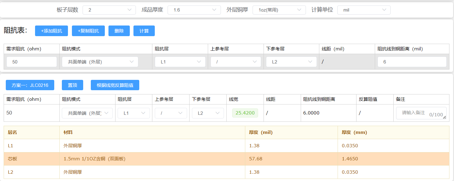
open-source license . Related features include a standby screen-off function to save energy. It provides 20 public walkie-talkie channels from 409.7500MHz to 409.9875MHz. Sub-tone technology is supported to effectively prevent crosstalk. Scrambling functionality is also supported, allowing for voice encryption and enhanced communication security. Users can flexibly switch between transmit/receive and monitoring modes to meet different scenario needs. In urban environments, the walkie-talkie's communication range can reach over 1 kilometer, with clear voice transmission and good intelligibility. It features a built-in power monitoring function to monitor battery level in real time. Furthermore, it supports power-off storage of parameter settings, improving the device's reliability and convenience. Project Attributes: This project is being publicly disclosed for the first time and is my original work. This project has not won any awards in other competitions. Project Progress : 2024.01.17 Project Initiation 2024.02.01 Design of Verification Board and Prototype Verification 2024.02.20 Prototype Verification Completed, PCB Design and Manufacturing Begin 2024.02.27 Soldering and Debugging 2024.03.10 Hardware and Software Debugging Completed 2024.03.12 Design and Printing of 3D Shell 2024.03.20 Modification of Shell and Program Functions 2024.04.16 Acceptance Completed Circuit Design Principle System Block Diagram Power Supply Circuit: The power supply section uses TP4056 for lithium battery charging and discharging. It is important to note that the circuit board does not include a lithium battery protection circuit; therefore, it is recommended to choose a lithium battery with a protection circuit to ensure safe use. The battery level monitoring uses a CW2015 chip, whose peripheral circuitry is relatively simple. The battery percentage and remaining runtime can be directly read via I2C communication. The main control circuit and RF module circuit are powered by XC6201 and SX1308 respectively. The SX1308 requires a pull-up to the EN pin to initiate voltage conversion. The AIR001 minimum system circuit uses a high-performance ARM Cortex-M0+ 32-bit core with a maximum operating frequency of 48MHz and supports low-power mode. Built-in memory includes 32KB Flash and 4KB SRAM. In addition, it features 9 timers, 1 12-bit ADC, and is equipped with 2 SPI interfaces, 1 I2C interface, and 2 USART interfaces. The peripheral circuit design is simple and can operate normally without an external crystal oscillator. The AIR001 minimum system circuit design only requires a pull-down of the boot pin and connection of a reset circuit. Independent Buttons: Considering the numerous GPIO ports on the air001, we adopted independent buttons for input. The functions of each button include select, cancel, up, down, left, and right. EEPROM Storage: In walkie-talkie operation, parameters such as frequency, sub-tone, scrambling, and volume level need to be set. If these settings had to be re-established every time the device is powered on, it would increase the complexity of use. Therefore, to facilitate user operation, we used the AT24C02 chip to store the relevant parameter data, implementing a power-off retention function for parameter settings, thereby improving the device's convenience. This chip uses I2C for communication, sharing the I2C bus with the CW2015 chip, reducing GPIO usage. RF Module: The RF module uses the SR_FRS_2WUS, a high-performance wireless voice and data transmission module with excellent cost-effectiveness. This module integrates a high-performance RF transceiver chip, microcontroller, and RF power amplifier. An external controller can communicate via a standard asynchronous serial interface (UART) to set the module's operating parameters and control the entire module's transmission and reception. This module only requires an external antenna, microphone, and voice amplifier to assemble into a complete walkie-talkie or data radio. The impedance matching section utilizes the "JALCEC Impedance Calculator" for simple calculation of trace width and includes a pre-installed pi-type impedance matching circuit for more precise impedance matching. If impedance matching is not required, L2 can be shorted by connecting a 0-ohm resistor for normal operation. The microphone input uses an electret condenser microphone for voice input. The audio output section uses an LM4871 audio power amplifier, capable of easily driving a 4-ohm 8W speaker, making it particularly suitable for small, lightweight portable systems. The LM4871's enable pin connects to the SQ pin of the RF module. When no signal is received, the LM4871 can be placed in sleep mode, effectively reducing power consumption and preventing noise output. Furthermore, the LM4871 has a built-in overheat automatic shutdown protection mechanism, stable operation, and adjustable unity gain. The amplifier's voltage gain can be easily adjusted by configuring an external resistor to meet different application requirements. The software section is mainly divided into five parts: OLED interface, button control, intercom module function settings, power reading, and parameter storage. The OLED interface and IIC communication are implemented using software, making implementation relatively simple. #ifndef __I2C_H #define __I2C_H #include "air001xx_hal.h" #define I2C_GPIO GPIOF #define I2C_SDA GPIO_PIN_0 #define I2C_SCL GPIO_PIN_1 #define I2C_GPIO_ENABLE() __HAL_RCC_GPIOF_CLK_ENABLE() #define I2C_CMD 0 //Write command #define I2C_DATA 1 //Write data void I2C_Init(void); void I2C_Start(void); void I2C_Stop(void); void I2C_WaitAck(void); void I2C_SendByte(uint8_t dat); uint8_t I2C_ReadByte(uint8_t ack); void OLED_WR_Byte(uint8_t dat,uint8_t mode);


#endif
air001 communicates with the OLED via IIC to set the display content.
void OLED_ShowChar(uint8_t x,uint8_t y,uint8_t chr,uint8_t size1,uint8_t mode)
{
uint8_t i,m,temp,size2,chr1;
uint8_t x0=x,y0=y;
if(size1==8)size2=6;
else size2=(size1/8+((size1%8)?1:0))*(size1/2); //Get the number of bytes occupied by the dot matrix set corresponding to one character of the font
chr1=chr-' '; //Calculate the value after offset
for(i=0;i>=1;
y++;
}
x++;
if((size1!=8)&&((x-x0)==size1/2))
{x=x0;y0=y0+8;}
y=y0;
}
The
button control
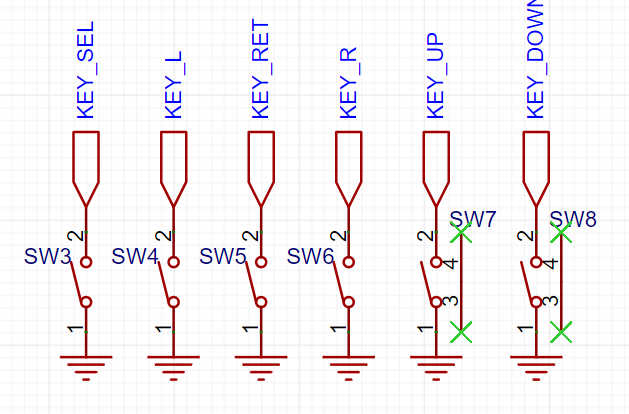
section uses six independent buttons, each with a function: confirm, cancel, up, down, left, and right. The buttons are scanned in a while loop within the main function to determine the pressed button and execute the corresponding program. The code snippet provided is:
`uint8_t Key_Scan(void)
{
if(HAL_GPIO_ReadPin(KEY_GPIOA,KEY_SEL_PIN)==0)
{
HAL_Delay(20);
if(HAL_GPIO_ReadPin(KEY_GPIOA,KEY_SEL_PIN)==0)
{
while(HAL_GPIO_ReadPin(KEY_GPIOA,KEY_SEL_PIN)==0);
return 1;
}
}else if(HAL_GPIO_ReadPin(KEY_GPIOA,KEY_RET_PIN)==0)
{
HAL_Delay(20);
if(HAL_GPIO_ReadPin(KEY_GPIOA,KEY_RET_PIN)==0)
{`
while(HAL_GPIO_ReadPin(KEY_GPIOA,KEY_RET_PIN)==0);
return 2;
}
}else if(HAL_GPIO_ReadPin(KEY_GPIOB,KEY_UP_PIN)==0)
{
HAL_Delay(20);
if(HAL_GPIO_ReadPin(KEY_GPIOB,KEY_UP_PIN)==0)
{
while(HAL_GPIO_ReadPin(KEY_GPIOB,KEY_UP_PIN)==0);
return 3;
}
}else if(HAL_GPIO_ReadPin(KEY_GPIOA,KEY_DOWN_PIN)==0)
{
HAL_Delay(20);
if(HAL_GPIO_ReadPin(KEY_GPIOA,KEY_DOWN_PIN)==0)
{
while(HAL_GPIO_ReadPin(KEY_GPIOA,KEY_DOWN_PIN)==0);
return 4;
}
}else if(HAL_GPIO_ReadPin(KEY_GPIOA,KEY_LEFT_PIN)==0)
{
HAL_Delay(20);
if(HAL_GPIO_ReadPin(KEY_GPIOA,KEY_LEFT_PIN)==0)
{
while(HAL_GPIO_ReadPin(KEY_GPIOA,KEY_LEFT_PIN)==0);
return 5;
}
}else if(HAL_GPIO_ReadPin(KEY_GPIOA,KEY_RIGHT_PIN)==0)
{
HAL_Delay(20);
if(HAL_GPIO_ReadPin(KEY_GPIOA,KEY_RIGHT_PIN)==0)
{
while(HAL_GPIO_ReadPin(KEY_GPIOA,KEY_RIGHT_PIN)==0);
return 6;
}
}
return 0;
}
Intercom module function settings
The walkie-talkie function settings use UART to communicate with the walkie-talkie module and set parameters via AT commands.
void Uart_TxData(uint8_t index, uint8_t level)
{
uint8_t *aTxBuffer;
uint8_t tx_len=0;
switch(index)
{
case 0://Volume
AT_CMD2[10] = 0x31+level;
aTxBuffer = AT_CMD2;
tx_len=13;
AT24CXX_WriteOneByte(ADDR_VOL, level);
break;
case 1://亚音
strncpy(AT_CMD1+30, subtone[level],2);
strncpy(AT_CMD1+33, subtone[level],2);
aTxBuffer = AT_CMD1;
tx_len=41;
AT24CXX_WriteOneByte(ADDR_SUB, level);
break;
case 2://RF switch
HAL_GPIO_WritePin(GPIOB, PD_PIN, level);
AT24CXX_WriteOneByte(ADDR_SW, level);
return;
break;
case 3://Scrambling frequency
AT_CMD4[16] = 0x30+level;
aTxBuffer = AT_CMD4;
tx_len=21;
AT24CXX_WriteOneByte(ADDR_SCR, level);
break;
case 4://Hands-free sensitivity
AT_CMD3[10] = 0x30+level;
aTxBuffer = AT_CMD3;
tx_len=13;
AT24CXX_WriteOneByte(ADDR_VOX, level);
break;
case 5://Squelch level
AT_CMD4[10] = 0x30+level;
aTxBuffer = AT_CMD4;
tx_len=21;
AT24CXX_WriteOneByte(ADDR_SQU, level);
break;
case 6://Microphone sensitivity
AT_CMD4[12] = 0x30+level;
aTxBuffer = AT_CMD4;
tx_len=21;
AT24CXX_WriteOneByte(ADDR_MIC, level);
break;
}
if (HAL_UART_Transmit_IT(&UartHandle, aTxBuffer, tx_len) != HAL_OK) {
Error_Handler();
}
} The CW2015 communicates with the main control chip via IIC to
read battery
information. Upon power-up, battery information is first set, and then the current battery level can be obtained by reading the value in the SOC register.
uint8_t CW2015_ReadOneByte(uint8_t ReadAddr)
{
uint8_t temp=0;
I2C_Start();
I2C_SendByte(0XC4); // Send data to device address 0XA0
I2C_WaitAck();
I2C_SendByte(ReadAddr); // Send data to low address
I2C_WaitAck();
I2C_Start();
I2C_SendByte(0XC5); // Enter receive mode
I2C_WaitAck();
temp=I2C_ReadByte(0);
I2C_Stop();// Generate a stop condition
The walkie
- talkie's channel and related function settings are stored in the AT24C02, enabling power-off memory storage. The AT24C02 communicates with the host via IIC. The specific storage format is as follows: | Address | Storage Content | Range | | --- | --- | --- | 0x00 | Volume | 0-7 0x01 | Sub-tone | 0-4 0x02 | RF Switch | 0-1 0x03 | Scrambling | 0-7 0x04 | Hands-free Sensitivity | 0-8 0x05 | Squelch Level | 0-9 0x06 | Microphone Sensitivity | 0-7 The core code uses `page_index` to determine whether the current page is the home page or the menu page. `current_index` and `temp_list_level` represent the currently selected function and its parameter level, respectively. Then, the OLED, UART, button GPIO, and CW2015 are initialized. Finally, a loop is entered, continuously checking the button press status to control the function. int main(void) { uint8_t page_index=0;//page index uint8_t current_index=0;//list index uint8_t temp_list_level = 0; uint8_t key_index = 0;//key index uint8_t i=0, list_len = (sizeof(list)/sizeof(MENU_LIST)); /* Initialize all peripherals, Flash interface, SysTick */ HAL_Init(); UART2_INIT(); Get_Init_Data(); Show_HomePage(list[0].current_level, list[2].current_level); CW2015_WriteOneByte(0x0a,0xff);//wake up cw2015 HAL_Delay(50); CW2015_WriteOneByte(0x0a,0x00);//wake up cw2015 HAL_Delay(50); uint8_t battary_data = 0; battary_data = CW2015_ReadOneByte(0x08); battary_data = battary_data & 0x02; HAL_Delay(50); if(battary_data == 0) { Update_Bat_Info(); } temp_list_level = list[0].current_level; while (1) { if(page_index == 0 && display_on) { OLED_ShowChar(8, 0, list[0].current_level + 0x30, 8, 1); battary_data = CW2015_ReadOneByte(0x04); HAL_Delay(50); OLED_ShowNum(127-24,0,battary_data,3,8,1); OLED_ShowChar(127-6,0,'%',8,1); OLED_Refresh(); } key_index=Key_Scan(); if(key_index == 1) { switch(page_index)//key_select { case 0://enter menu if(display_on){ page_index +=1; current_index=oled_showlist(list_len, current_index, (MENU_LIST *)list, 2); }else{ Show_HomePage(list[0].current_level, list[2].current_level); display_on = 1; } break; case 1://select setting list[current_index].current_level = temp_list_level;
Uart_TxData(current_index, list[current_index].current_level);
break;
default:
break;
}
}else if(key_index == 2)//key_return
{
switch(page_index)
{
case 0://none
display_on = 0;
OLED_Clear();
OLED_Refresh();
// current_index=oled_showlist(list_len, current_index, (MENU_LIST *)list, 1);
break;
case 1://return home page
page_index -= 1;
Show_HomePage(list[0].current_level, list[2].current_level);
current_index=0;
break;
default:
break;
}
}else if(key_index == 3)//key_up
{
if(page_index == 1)//current is menu page
{
current_index=oled_showlist(list_len, current_index, (MENU_LIST *)list, 0);//previous(up)
temp_list_level = list[current_index].current_level;
}else
{
Set_Level_Silent((MENU_LIST *)list, 0, 1);
Uart_TxData(0, list[0].current_level);
}
}else if(key_index == 4)//key_down
{
if(page_index == 1)
{
current_index=oled_showlist(list_len, current_index, (MENU_LIST *)list, 1);//next(down)
temp_list_level = list[current_index].current_level;
}else
{
Set_Level_Silent((MENU_LIST *)list, 0, 0);
Uart_TxData(0, list[0].current_level);
}
}else if(key_index == 5)//key_left
{
if(page_index == 1)
{
temp_list_level= Set_Level((MENU_LIST *)list, current_index, temp_list_level, 0);
}else{
channel_index = Uart_SetFreq(channel_index, 0);
}
}else if(key_index == 6)//key_right
{
if(page_index == 1)
{
temp_list_level = Set_Level((MENU_LIST *)list, current_index, temp_list_level, 1);
}else
{
channel_index = Uart_SetFreq(channel_index, 1);
}
}
key_index = 0;
}
}
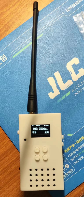
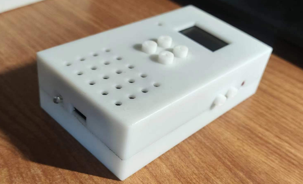
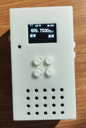
Physical Demonstration
Physical Function Introduction

Physical Appearance Demonstration

Design Notes
The circuit design does not include a lithium battery protection circuit. It is recommended to purchase a lithium battery with a protection circuit to ensure safe use.
When programming, it is recommended to use the DAPLink debugger (theoretically, programming can also be done via serial port). When using DAPLink for programming, ensure that the programmer's 3V3 and GND are connected to the board to avoid the possibility of programming failure. If programming failure occurs, you can appropriately reduce the programmer's clock frequency and try again.
When using CW2015, you need to write the battery information first and then read the SOC to ensure that the read SOC value is accurate. For details, please refer to: CW2015 Fuel Meter Usage
Notes The EN pin of the SX1308 chip controls a voltage conversion switch, not an output switch. When the EN pin is connected to a low level, the chip will still output voltage. This issue may not have been noticed in the initial design; it has been corrected in the schematic and PCB layout.
The antenna matching circuit should be soldered as needed. If impedance matching is unavailable, a 0-ohm resistor can be used to short-circuit it, which has been verified to achieve communication over longer distances.
Do not press the PTT button when the antenna is not connected, as this may cause unforeseen consequences.
The dimensions and wiring sequence of the soft-pack lithium battery interface are: 1.25mm black and red
. **Important Note:**
This project is for educational and communication purposes only. Please comply with relevant laws and regulations when using it for testing! [Related links:
Regulations of the People's Republic of China on Radio Management, Notice
on Issues Concerning the Management of Public Walkie-Talkies ]


 京公网安备 11010802033920号

 1N6107USX


