I. Design Objectives
and Basic Requirements
: Motion Function: Able to flexibly turn, move forward and backward smoothly at an appropriate speed, and complete the entire tracking route within two minutes;
Automatic Control Function: Able to automatically move forward along a white background and black tracking line; Able to identify obstacles on the obstacle avoidance route and avoid them along a reasonable path, automatically returning to the tracking route after avoidance; Stops and sounds the horn at designated markers, simulating an intersection warning function;
Additional Functions
: Can be switched to an external remote controller, such as using Bluetooth, Wi-Fi, or 2.4G remote control, to control the car's movement;
Visually appealing with aesthetic value;
The car body has sufficient strength and load-bearing capacity.
II. Hardware Design
Completer: YiRen
Mechanical Structure:
Overall Frame:
Base Plate + 4 Motors + Tracking and Obstacle Avoidance Module + Battery Box + Main Control Board + Connecting Cables
Base Plate:
No separate base plate shell is made; a 1.6mm thick PCB circuit board (FR-4 fiberglass) with sufficient strength is used. The white silkscreened square marked "n20 Motor Position" on the base plate is used to reserve the position for installing the motor on the top of the base plate; the larger white rectangle in the middle section is the position of the battery box, and the smaller white rectangle is used to install the DC-DC step-down module; the rear wheels of the car are installed on both sides of the narrower area on the left, and the right side is used for... The front wheels are installed in a flexible position, potentially in the central empty area. In this case, a shorter coupling is used for the rear wheels, significantly reducing the vehicle's width and improving aesthetics while also reducing size. However, this compromises differential steering and requires a higher-powered motor. Considering the relatively low-power motor used in this project, the front wheels are mounted on the outer side of the base plate, while the rear wheels use an extended coupling to increase the vehicle's steering flexibility. The central empty area is used to install a load box and can also accommodate additional functional loads such as a spare battery, camera, or audio system. Holes in the base plate are used to secure components with nylon posts.

Motor:
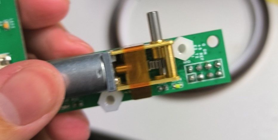
After research and discussion, an N20 geared motor was chosen for its simple structure, small size, strong driving force relative to its weight, and high torque. Steering is achieved using differential steering on both side wheels.
The initial design concept was to create a motorcycle-like appearance with a narrow body. Therefore, a modified N20 motor with a worm gear drive was chosen, where the rotating rod is located on the side of the motor. This reduced the width of the vehicle and facilitated a closer fit of the wheels to the base plate, further reducing the width. However, due to revisions in the final design, this width-reduction advantage was not realized. Furthermore, since worm gears have power losses, replacing them with a standard N20 motor would improve the vehicle's performance, but would require modifications to the mounting holes.
The group tested two models of N20 worm gear motors at 12V: one with a 381 RPM reduction ratio of 42 and the other with a 60 RPM reduction ratio of 236. The former could reach speeds approaching one meter per second, but stopped abruptly in differential steering mode due to insufficient torque. The latter, while slower, offered stable steering. Ultimately, the latter was chosen to ensure the stability of differential steering.
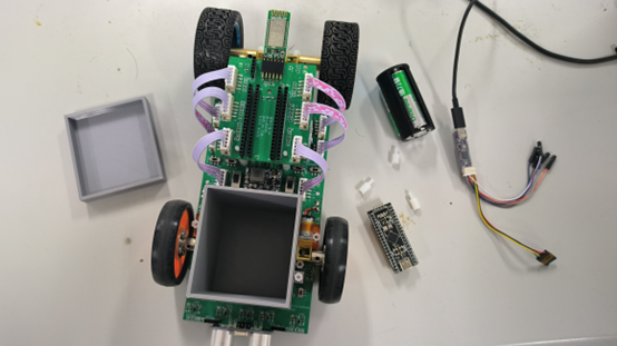
Regarding motor mounting, a motor bracket specifically designed for the N20 worm gear motor was unavailable, and the author had not yet mastered 3D printing technology when creating the PCB. A sudden inspiration led to the use of two nylon pillars for positioning, with the motor secured to the PCB baseboard using cable ties (as shown in the image below). Testing revealed excellent fixation.
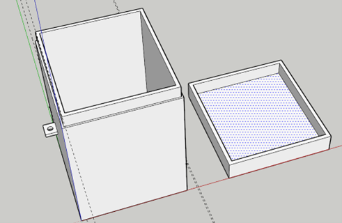
Load Box:
After modifying the tire position, to fully utilize the remaining space on the baseboard, an expansion function was designed in the area originally reserved for the front wheels. This was achieved by adding an expansion block using the copper pillar mounting holes on the baseboard. This location can be used to install cameras, speakers, and various environmental detection modules, etc. To simulate this expansion capability, a square load box was designed here. The load box is made of PLA and manufactured using 3D printing. The mounting components are side lugs with mounting holes on both sides of the box, which are fixed to the base plate with studs. The 3D model and the actual product are shown below:
Battery Box:
Initially, two 3.7V minimum voltage, model 14500 lithium batteries were used for power supply. Later, to enhance forward momentum and steering speed, three 3.7V batteries were used. After purchasing a cylindrical three-cell battery box connected in series, a 3D-printed battery box of suitable size, sufficient strength, and lightweight design was used to accommodate and connect the cylindrical three-cell batteries. The material is PLA, and the bottom has many cutouts for easy hot melt adhesive filling.


Wheels:
The rear wheels use 65mm diameter wide rubber wheels to enhance grip. An extended hexagonal coupling connects the wheels to the motor, increasing the rear wheel clearance. The front wheels use high-strength silicone narrow wheels to reduce friction and increase load-bearing capacity. In actual testing, the load box can move forward without deceleration when carrying a 500g load. The front wheels are connected to the motor using a matching flange coupling.
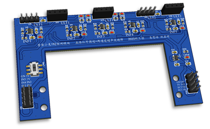
Line tracking and obstacle avoidance module:
The main body of the line tracking and obstacle avoidance module is a wide U-shape, with the same width as the main board. The mounting holes are designed according to the main board. It can be connected to the 5V power supply network of the car's chassis through a 2.54mm-8P interface. Through this interface, the detection signal is transmitted to the microcontroller through the chassis socket and ribbon cable. The line tracking part is designed with five-channel infrared line tracking, and the obstacle avoidance part is designed with dual channels and five connectors. From left to right, sockets 1, 2, and 3 are channel one, and 4 and 5 are channel two. It can realize single-channel or dual-channel ultrasonic ranging and obstacle avoidance. The front of the line tracking module uses a high-brightness LED as a headlight.
Connection components:
The multi-channel signal connection between modules across boards uses 2.54mm-8P pins, 2.54mm-6P-XH ribbon cables, and matching sockets, and is mechanically fixed with nylon pillars, copper pillars, and nuts.
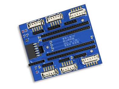
Main Control Module:
To facilitate the replacement of the main control chip and subsequent improvements, and to allow the Bluetooth communication module to receive signals from the roof, the main control chip is separated from the baseboard. An expansion PCB for the main control module is designed, which is fixed to the baseboard with nylon pillars through three limiting holes. A 6-pin ribbon cable is used to exchange signals with the baseboard. The main control chip is STM32F411CBU6. The core system module of the expansion PCB is placed on the connector pins. There is a row of connector pins on each side to expand its pins. 0-ohm surface mount resistors are used where the connector pins connect to the ribbon cable socket to facilitate disconnection during debugging and changing the connection pins of the socket with DuPont wires. A Bluetooth module socket is reserved on the board.
Circuit Design:
Baseboard:
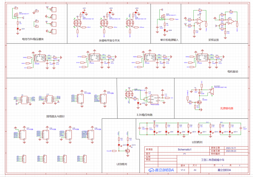
Power Supply:
The power supply section uses three 3.7V lithium batteries in series (12.6V when fully charged) as the total input. A 5V (5A) power supply network is generated by a SY8205 switching step-down circuit. A 3.3V (0.5A) network is obtained by an RT9013-33 linear regulator circuit. A switch is placed to control the total input and the 5V network input to the main control.
Toggle Switch Set:
Three toggle switches control the microcontroller pins to connect to a 3.3V high level or remain idle, respectively toggling the software-level Bluetooth, line tracking, and obstacle avoidance functions.
Motor Driver:
The AT8236 motor driver chip is used, with the circuit topology designed according to the datasheet reference. It can withstand a maximum current of 6A, with a 3A current threshold set to prevent stalling and burnout of the motor and driver chip. The motor driver circuit is placed under the chassis where airflow is frequent to ensure good heat dissipation.
Sampling Amplifier:
One differential amplifier reduces the battery voltage by 5.1 times and outputs it to the microcontroller's DAC to obtain the battery status. Another differential amplifier converts 5V to 3.3V to generate a reference level.
Passive Buzzer:
The microcontroller controls the MOSFET's conduction and cutoff via PWM waves to vibrate the buzzer and generate sound.
Line Tracking and Obstacle Avoidance Module:

Power Supply:
Connected to the chassis's 5V power supply network. The 5V powers the ultrasonic module and the LEDs of the infrared switch pair. An RT9013-33 linear regulator chip generates the 3.3V power supply for the module.
Infrared Tracking Module:
The infrared photoelectric switch uses an ITR9909, with the transmitting tube powered by 5V and the receiving tube by 3.3V, adapting to the input range of the subsequent comparator signal. The comparator is a TLV3201 push-pull high-speed comparator, with a 3.3V power supply to adapt to the input range of the microcontroller pins. Two 0603 surface-mount resistors are used at the negative input terminal instead of a potentiometer to adjust the comparison voltage, saving space. When the photoelectric switch scans a black line, it outputs a high level; when it scans a white area, it outputs a low level.
Ultrasonic Obstacle Avoidance Module:
An HC-SR04 ultrasonic ranging module is used. After a short high-level activation, it outputs a high-level signal with a duration proportional to the distance. It is connected to the module via a 4P header and powered by 5V.
Main Control Module:

The main control module primarily expands the functionality of the MCU core board. The main components are a 20P header for connecting to the core board, an XH-2.54-6P socket, and a 0-ohm resistor. A header is also reserved for connecting a Bluetooth module, and LEDs and MOSFET switches are provided to indicate the Bluetooth connection status. The core board selected is the F411CEU6 core board from Micro-Motion Studio, and the Bluetooth module is the Huicheng HC08 Bluetooth module.
III. Software design
completed by: Antimo.
The software part of this innovative project adopts the CubeMX generation framework and is programmed using the Keil integrated development environment. In the "Code Generator" section, you can set the file generation method: check "Generate peripheral initialization as a pair of '.c/.h' files per peripheral", so that CubeMX generates a pair of `.c` and `.h` files for each peripheral, which is convenient for subsequent personalized configuration of peripherals.
The following details the program implementation of infrared tracking and ultrasonic obstacle avoidance, and briefly explains the implementation of other peripherals.
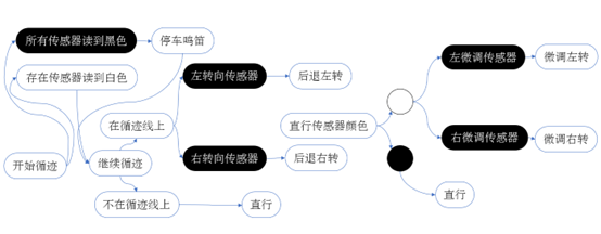
Infrared tracking
This project uses five-way tracking. The tracking sensors are divided into three categories: straight-line sensor (3), fine-tuning sensor (2, 4) and steering sensor (1, 5), which are installed in the center of the front of the car, on both sides of the straight-line sensor, and on the left and right corners of the front of the car, respectively.
In addition, the driving system of the car is briefly explained here, and will not be repeated later. The car uses a worm gear 1218-N20 reduction motor with two electrodes. The effects of different input levels or PWM waveforms are as follows [3]:
IN1
IN2
Motor effect
Low level
Low level
Smooth forward
High
level Low level Forward rotation Low level High
level Reverse high level High level Lock PWM 0 Forward rotation, fast decay 1 PWM Forward rotation, slow decay 0 PWM Reverse rotation, fast decay PWM 1 Reverse rotation, slow decay In actual use, we use PWM to control the motor speed so as to control the car speed more flexibly. The PWM input of the motor can be changed using the __HAL_TIM_SET_COMPARE function. In fact, an inline statement can be used to write a function body in the USER CODE area to enhance the readability of the code, but since this operation is really optional, we did not do it. The advantage of marking five-way tracking onTest is that if the straight sensor detects the tracking line, the car will go straight at full speed regardless of the detection of other sensors. This can greatly save the number of times the PWM duty cycle is changed and save memory space. The tracking algorithm first needs to determine whether the car is on the tracking track, and then it can move according to the rules. We use OnTest to indicate whether the car is on the track. If all five pins read white, there are two possibilities: the car is not on the track, or the car is on the track but the tracking line is stuck between two sensors and the car's direction of travel is parallel to the tracking line. If these two situations are not distinguished, the car will not know its state (because all states of infrared tracking require a sensor to read black), leading to errors. Therefore, we must clarify these two states. Based on the above requirements, we can design the OnTest check as follows (this is the design we are most proud of in this algorithm section): If all five pins read white and OnTest == 1, we let the car rotate randomly by a small angle (lines 213-236 in main.c), so that the car is no longer parallel to the tracking line. After this, if all five pins still read white, it proves that the car is indeed outside the tracking line, and OnTest = 0. When the car is not on the track, we let the car move straight until it finds the tracking line. That is, until one of the car's sensors reads black, OnTest becomes 1. During debugging, since we can't always be aware that we've perfectly positioned the car on the tracking line, this method of letting the car move forward to find the tracking line is very useful. When the car is on the track, it performs normal tracking. If all five pins read white, as mentioned earlier, we can turn the car slightly so that its path is no longer parallel to the tracking line, allowing it to automatically move onto the tracking line. It's important to note that when turning the car slightly, the motor needs to maintain the steering state for a period of time (lines 224 and 234), otherwise the car will revert to straight-line mode the instant it turns, causing steering failure. Tracking Algorithm Implementation: When the car is on the tracking line, we use a general tracking algorithm, continuously correcting the car's direction to maintain its movement on the tracking line. Straight-line sensor reads black (lines 302-311 in main.c). This indicates that the car is on the tracking line and moving along its direction. Due to the characteristics of five-way tracking, we don't need to change the car's direction; it can simply move in a straight line at full speed. Straight-line sensor does not read black. (Lines 312-334 of main.c) If the straight-line sensor does not read the black line, but the adjacent fine-tuning sensor does, it means the car's direction has deviated from the tracking line and fine-tuning is needed. For precise fine-tuning, we keep one motor running normally while stopping the other, thus achieving differential steering. For example, when pin 2 (the left fine-tuning sensor) reads black, the car should turn slightly to the left. At this time, the left motor stops, and the right motor continues at its original speed. When pin 3 reads the black tracking line again, the car resumes straight-line driving. In practice, it's best not to stop one motor for differential steering, as excessive changes in the PWM duty cycle can reduce motor lifespan. However, in reality, reducing the PWM on the differential side to 70% can cause the fine-tuning speed to be too fast, causing the car to run off the tracking line and ultimately fail to track. When encountering curves or even right-angle turns, ordinary differential steering cannot be achieved. This is where the steering sensor comes in handy. Therefore, the steering sensor has higher priority than the straight-line and fine-tuning sensors.
The steering sensor reads black. (Main.c lines 274-300) Due to uneven friction on the ground, the car's axis is not constant during differential steering; sometimes the car will move backward, but the general trend is forward. If the car continues to move forward when making a sharp turn, it will inevitably run off the tracking track, resulting in immediate failure. Therefore, we need to design the steering to allow the car to move backward. When the steering sensor reads black, we reverse the PWM on the centripetal side with 90% and rotate the PWM on the opposite side with 50% forward, thus enabling the car to steer backward. The reason for not setting the PWM to 100% is to prevent excessive friction from the tires, which could lead to excessive torque and cause the car's structure to disintegrate, and to protect the motors and extend their lifespan.
Furthermore, according to track requirements, the car needs to stop and sound its horn when encountering a stop indicator (lateral tracking line). Therefore,
when all sensors read black, the car stops and sounds its horn for 5 seconds. (main.c lines 250-272) The horn uses PWM to control the horn volume, and the horn frequency is determined to be 3000Hz by a preset period.
Infrared Tracking Flowchart
The room for improvement of infrared tracking
In the process of implementing the current version of infrared tracking, we have not given up thinking about how to improve the infrared tracking algorithm.
We found that directly modifying the PWM operation will damage the motor and cause the car to bump a lot during the movement (if there are passengers in the car, they will definitely feel dizzy from the multiple short intervals of acceleration change), so there is a lot of room for improvement. Our proposed subsequent improvement method is to make the acceleration of the car change continuously. For example, the PWM changes by 1% every 10 microseconds.
Further exploring this idea, we believe that if a gyroscope or speed detection device is added with sufficient funds, and a negative feedback system is used when changing the speed, it may make the change of the car speed smoother.
Ultrasonic obstacle avoidance
In ultrasonic obstacle avoidance, we refer to and implement our own ultrasonic ranging function based on the example given by CSDN[1]. For
ultrasonic ranging,
we use the HC-SR04 component. Its principle is as follows:
Transmitting an ultrasonic pulse: The HC-SR04 module generates a short ultrasonic pulse through its transmitter.
Receiving the ultrasonic echo: The transmitted ultrasonic pulse propagates to the surface of the target object and is reflected back. The receiver on the HC-SR04 receives this echo.
Time measurement: After the ultrasonic wave is transmitted, the HC-SR04 starts timing until the echo is received. It measures the time interval between the transmission and reception of the ultrasonic pulse.
Distance calculation: Using the known speed of sound (approximately 340 m/s in air), the module converts the received time interval into the distance between the target object and the sensor. Typically, this time interval multiplied by half the speed of sound gives the distance to the target object.
The HC-SR04 module calculates the distance by measuring the sound wave propagation time and then transmits the distance information to a connected microcontroller, enabling it to perform corresponding operations or control other devices. This module is simple and easy to use and is widely used in obstacle avoidance, ranging, and positioning.
Ultrasonic ranging is implemented using PWM interrupts and microsecond-level timers. See hc-sr04.h for details, which will not be elaborated upon here. Due to the complex obstacle
avoidance
environment in actual testing, including non-target obstacles such as table corners and walls, and with limited budget and technical resources, we could only guide the car to avoid obstacles in areas with minimal interference. By setting the parameter Turned to 1 (line 51 of main.c) and controlling the limitation in line 155 of main.c, we ensured that the car only avoided an obstacle once per startup.
Due to the characteristics of the HC-SR04 module, it randomly returns a small distance upon startup, which might cause the car to perceive an obstacle ahead. To address this, we wrote a filtering function (lines 48-68 of hc-sr04.c) and output the filtered value each time the distance is read (line 139 of hc-sr04.c).
The obstacle avoidance method used in testing pre-defined obstacle avoidance routes: when the distance to an obstacle is 10cm, the car avoids it by turning left, going straight around it, and then turning right back to the track. Through repeated testing, we obtained the following specific data: left turn 1.9s, straight ahead leaving the track 2.7s, right turn 2.15s, straight ahead returning to the track 2.4s. (main.c lines 155-200)
Ultrasonic Obstacle Avoidance Flowchart.

Improvement of Ultrasonic
Obstacle Avoidance: The disadvantage of preset obstacle avoidance routes is that the obstacle avoidance location and the type of obstacle are limited; basically, it can only avoid our preset small box obstacles within our preset area. Considering this, we came up with the following improvement method:
add an ultrasonic module and change the position of the ultrasonic ranging module so that it can measure the distance from the left and right sides of the car to the obstacle. Use a timer interrupt to maintain the distance from the side of the car to the obstacle always greater than 10cm. In this way, the car will walk close to the edge of the obstacle until it returns to the tracking line.
Since we reserved two input/output pins for ultrasonic sensors in the initial design of the base plate and set 5 positions for installing ultrasonic sensors on the portable module, this method can theoretically be implemented on our car. However, although this method is excellent, due to time constraints and our lack of experience in interrupt programming, it could not be completed before testing. However, we will still explore this method.
Other peripherals:
The hardware and software implementation of some other peripherals are briefly introduced below.
Status control and detection:
In the initial design of the baseboard, we reserved status detection interfaces for each module to facilitate timely judgment of whether each module is operating normally during actual use.
Among them, 3V3REF can detect whether the infrared module and ultrasonic obstacle avoidance are ready. If they are not ready, functions such as line tracking and obstacle avoidance cannot start. At this time, we make the car move straight to test whether the car can run, because when initially testing whether the car can move, we need to eliminate interference from other modules to the car's motion system; 3V3 returns whether the motor is enabled. If so, it can rule out the car not moving due to the motor not being turned on (and in fact, we did encounter this situation, and we quickly found the problem when the driver module was not connected to the motherboard).
OPINF and OPULT are for infrared line tracking and ultrasonic obstacle avoidance ready, respectively. The corresponding functions can only be performed after they are ready. OPBLUE is for Bluetooth connection. If Bluetooth is connected and an AT command is entered, Bluetooth control mode can be enabled. ALLLED provides feedback on whether the LEDs in the circuit are working properly. If an LED fails to light up when it should, it may not be due to a failure of its associated peripheral, but simply a failure of the LED itself. The VMES series pins
for power detection
can read the battery level from the preset ADC input and provide real-time feedback, making it easy to detect if insufficient battery power is the cause when the car stops moving. The battery level is transmitted in real-time to the Bluetooth control center on the mobile phone via the Bluetooth module . The CONBUZ pin of
the buzzer outputs a PWM signal to control the volume of the car's buzzer. The buzzer
frequency is preset to 3000Hz in CubeMX. The car uses the USART6 pin for Bluetooth communication. Bluetooth communication allows for debugging using the printf function, greatly speeding up the debugging process. IV. Hardware and Software Integration Completed by: Antimo & YiRen Microcontroller Pin Assignment and Corresponding Naming: See Appendix 1:
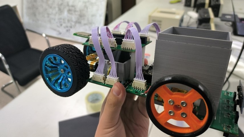
V. Actual Product
VI. Product Testing
In the actual testing phase, the product completed the prescribed track, including one obstacle avoidance maneuver, a right-angle turn, and a 5-second stop at a traffic light. The self-test time was 1 minute and 21 seconds. During the assessment phase, the battery level decreased, and the completion time was 1 minute and 31 seconds.
VII. Costs and Actual Expenses
Note: This cost estimate only considers a single product and does not include other costs and contingencies incurred during the design phase.
Rubber rear wheels 2*6=12;
Silicone high-strength wheel hubs front wheels 2*28=56;
Worm motor and coupling 4*20=80;
Delipe 14500 lithium battery 3.7V 10*3=30;
Three cylindrical battery holders 1*5=5;
TL082 op-amp, socket, four-color LED, TLV3201 comparator total 34;
STM32F411CEU6 core board 1*23=23;
5V switching power supply step-down module 1*11=11;
HC-08 Bluetooth module including debugging rack 1*28=28;
Nylon pillars, copper pillars, ribbon cables, nuts, ultrasonic ranging module total 25;
Motor driver chip, switch, socket, linear regulator, infrared switch, buzzer total 60;
Car chassis PCB board making fee (minimum order 5 sheets) 66;
The total cost of the above 12 items is 430 yuan.
Other:
In the early design stage, during the exploration of motorcycle structure, we purchased many kinds of wheels, connectors, mechanical bogies, servos and accessories, etc., which cost an additional 160 yuan. At the same time, we tried a high-speed low-torque motor (including its mounting bracket) which cost an additional 60 yuan. Therefore, the design cost of this industrial innovation activity group was around 650 yuan.
Appendix 1: Naming, Functions, and Microcontroller Pin Correspondences of Each Interface of the Car
Car-Control Board Interaction Port Information:
Format: Port Name - Output/Return (for Microcontroller) - Meaning - Type
3V 3REF Returns true value 1 indicates the infrared module and ultrasonic obstacle avoidance are ready. High/Low Level (IO)
Infrared Tracking Section:
INF1 Returns the first infrared sensor from the left, black corresponds to high level; white corresponds to low level. High/Low Level (IO)
INF2 Returns the second infrared sensor from the left, black corresponds to high level; white corresponds to low level. High/Low Level (IO)
INF3 Returns the third infrared sensor from the left, black corresponds to high level; white corresponds to low level. High/Low Level (IO)
INF4 Returns the fourth infrared sensor from the left, black corresponds to high level; white corresponds to low level. High/Low Level (IO)
INF5 Returns the fifth infrared sensor from the left, black corresponds to high level; white corresponds to low level. High/Low Level (IO)
Ultrasonic Obstacle Avoidance Section:
TR1 Outputs the first ultrasonic sensor from the left, high level for more than 10us triggers the periodic signal (Timer - duty cycle).
ECH1 Returning to ultrasonic sensor #1 from the left, the high-level duration represents the distance high/low level (IO interrupt).
TR2 outputs ultrasonic sensor #2 from the left, a high level above 10µs triggers a periodic signal (Timer - duty cycle)
. ECH2 returns to ultrasonic sensor #2 from the left, the high-level duration represents the distance high/low level (IO interrupt).
Motor control section:
M1N1 outputs left front wheel motor IN1 high/low level (IO) or PWM (timer-pwmout).
M1N2 outputs left front wheel motor IN2 high/low level (IO) or PWM (timer-pwmout).
M2N1 outputs left rear wheel motor IN1 high/low level (IO) or PWM (timer-pwmout).
M2N2 outputs left rear wheel motor IN2 high/low level (IO) or PWM (timer-pwmout).
M3N1 outputs right front wheel motor IN1 high/low level (IO) or PWM (timer-pwmout).
M3N2 outputs right front wheel motor IN2. High/Low Level (IO) or PWM (timer-pwmout)
M4N1 Output Right Rear Wheel Motor IN1 High/Low Level (IO) or PWM (timer-pwmout)
M4N2 Output Right Rear Wheel Motor IN2 High/Low Level (IO) or PWM (timer-pwmout)
Status Control and Feedback Section:
3V3 Returns motor enable truth value 1 indicates ready High/Low Level (IO)
VMES Returns battery power detection voltage / 3.3 Ω (below 7.7 Ω indicates low battery) ADC signal
OPINF Returns high level to enable infrared tracking High/Low Level (IO)
OPULT Returns high level to enable ultrasonic obstacle avoidance High/Low Level (IO)
OPBLUE Returns high level to enable Bluetooth High/Low Level (IO)
ALLLED Outputs high/low level signals to illuminate one LED High/Low Level (IO)
CONBUZ Outputs PWM signal (timer-pwmout) to drive the buzzer
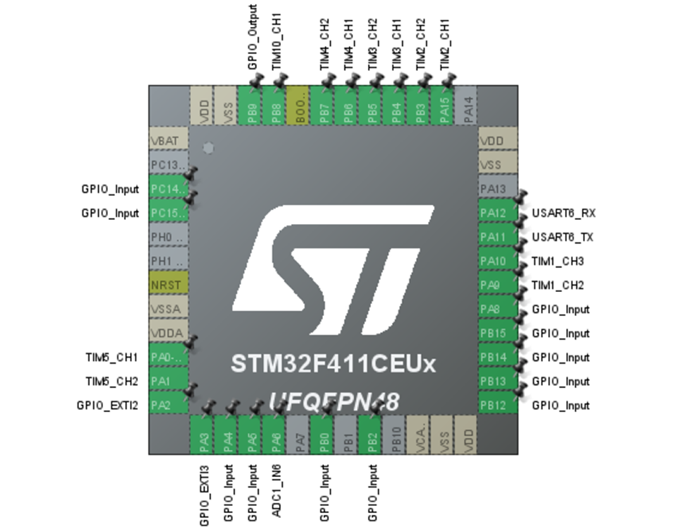
STM32F411CEU6 Pin Assignment and Signature (Pin-Option-Function)
PB12-GPIO_INPUT-INF1; PB13-GPIO_INPUT-INF2; PB14-GPIO_INPUT-INF3;
PB15-GPIO_INPUT-INF4; PA8-GPIO_INPUT-INF5;;
PA9-TIM1_CH2-M1N1; PA10-TIM1_CH3-M1N2;
PA15-TIM2_CH1-M2N1; PB3-TIM2_CH2-M2N2;
PB4-TIM3_CH1-M3N1; PB5-TIM3_CH2-M3N2;
PB6-TIM4_CH1-M4N1; PB7-TIM4_CH2-M4N2;
PB8-TIM10_CH1-CONBUZ; PB9-GPIO_OUTPUT-ALLLED
PC15 - GPIO_INPUT - OPINF; PC14 - GPIO_INPUT - OPULT;
PB0 - GPIO_INPUT - OPBLUE;
PA0 - TIM5_CH1 - TR1; PA1 - TIM5_CH2 - TR2;
PA2 - GPIO_EXTI2 - ECH1; PA3 - GPIO_EXTI3 - ECH2;
PA4 - GPIO_INPUT - 3V3REF;
PA5 - GPIO_INPUT - 3V3; PA6 - ADC1_IN6 - VMES;
Pin assignment diagram (excluding Bluetooth communication section)
Bluetooth pins:
PB2 - GPIO_IN - Bluetooth state - High level indicates connected, low level indicates not connected.
PA12 - USART6_RX (Asyn) - Connects to Bluetooth module. TX - Serial communication.
PA11 - USART6_TX (Asyn) - Connects to Bluetooth module. RX - Serial communication.


 京公网安备 11010802033920号

 1N4004AT-93X


