Project Overview:
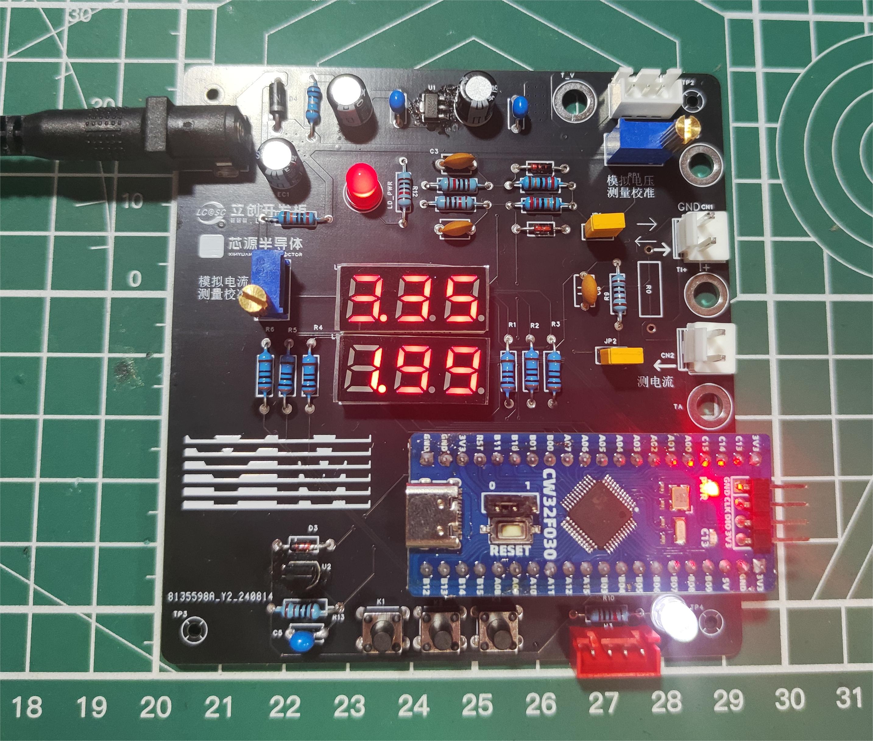
This project is a voltage and current meter based on the CW32 microcontroller.
Through the JLCPCB training camp, this project aims to provide practical experience in the entire process of circuit design, PCB layout, PCB prototyping, component selection, soldering, programming, and debugging, thereby achieving the goal of introducing beginners to electronic project design and fabrication.
The digital voltage and current meter project covers multiple aspects, including microcontroller circuit design and implementation, signal acquisition and processing circuit design, user interface development and optimization, and product appearance design, integrating knowledge from multiple fields such as electronics, microcontroller programming, circuit design, and industrial design. It is highly suitable for beginners in electronics and those who want to delve deeper into microcontroller applications. This project has the following highlights:
It adopts a core board plus expansion board design concept and uses plug-in components, making learning simpler and exploration more in-depth;
the core board uses the domestic Wuhan Xinyuan Semiconductor CW32 as the main controller, while also being compatible with other similar development boards; however, the CW32 has advantages.
The project has a high degree of integration and strong practicality; after completion, it can be used as a desktop everyday instrument;
the project has abundant learning materials, including circuit design tutorials, PCB design, code programming learning, and training for engineers' debugging skills.
Project Functionality:
This voltmeter and ammeter project features both analog and real-world voltage and current measurement capabilities.
It utilizes a voltage divider circuit for high-voltage acquisition, designed to acquire up to 100V, with a current configuration of 0-30V. Two voltage ranges are available with automatic switching. The
designed sampling current is 3A. No operational amplifier is used in this project, resulting in a gain of 1. To handle different operating environments, especially high-current scenarios, resistor R0 can be replaced with constantan wire or a shunt, allowing for selection based on specific application scenarios.
Cost Calculation:
The development board is sponsored by LCSC, originally priced at 9.9 RMB, discounted to 0.9 RMB (shipping costs not included).
The PCB is provided free of charge by JLCSC with free prototyping and shipping.
Components purchased from the LCSC online store originally cost approximately 100 RMB; LCSC sponsored a 50 RMB component coupon, bringing the price down to approximately 50 RMB. The actual component cost is less than one-tenth of the original price.
The total cost per unit is approximately 20 RMB or less.
Principle Analysis (Hardware Description)
This project consists of the following parts: power supply, voltage sampling circuit, current sampling circuit, digital tube display, voltage measurement calibration or reference circuit, and the Diwenxing development board as the main controller.
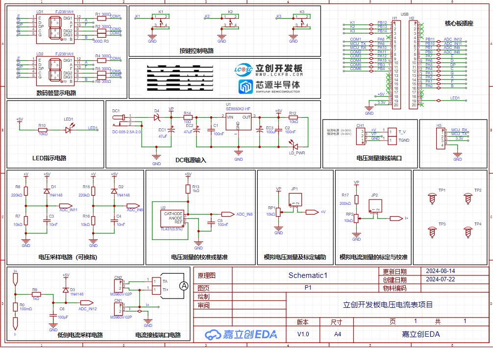
Example Figure 1 - Schematic Diagram
Power Supply:
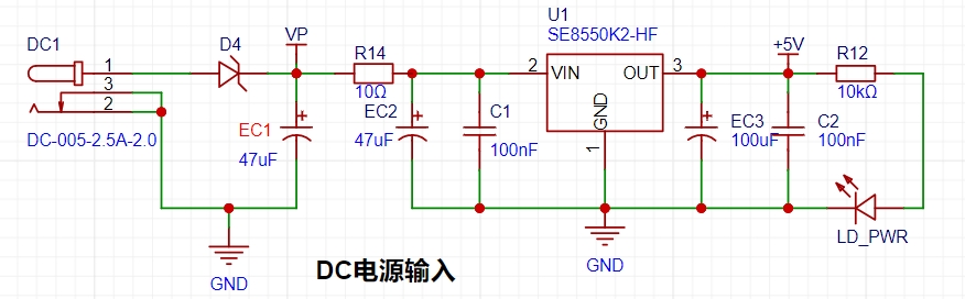
This project uses a DC interface as the power supply interface and an LDO as the power supply. Considering that most actual voltmeter products are used in industrial scenarios with 24V or 36V power supply, this project selected the SE8550K2 with a maximum input voltage of up to 40V as the power supply. The main reason for not using a DC-DC step-down circuit to deal with large voltage differences is to avoid introducing DC-DC ripple interference during the design process, and the secondary reason is to reduce project costs.
Voltage Sampling Circuit
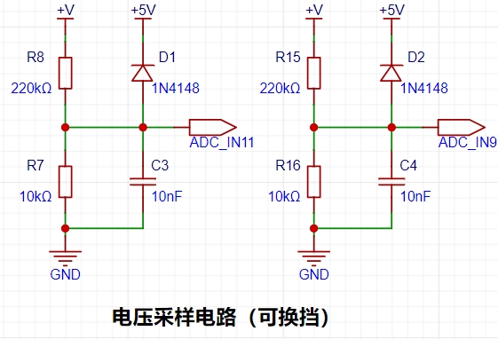
In this project, an additional voltage sampling circuit is added. Implementing this function requires a combination of hardware and software. When the ADC_IN11 channel measures a voltage within 30V, if the measured voltage is within 0~3V, the ADC_IN9 channel is used for measurement. At this time, due to the reduced voltage division ratio, the measurement accuracy is greatly improved.
The current sampling circuit
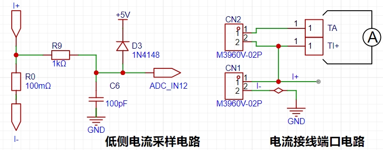
in this project uses a low-side current sampling circuit for current detection. The low-side of the sampling circuit shares a common ground with the meter interface on the development board. When learning, please do not solder R0!
Since this project does not use an amplifier circuit, a larger sampling resistor is needed to obtain a higher measured voltage for measurement. Considering that a larger resistor will result in a larger voltage drop and higher power consumption, an unlimited selection of a larger resistor is not possible. This project uses a 1W package resistor, corresponding to a 1W power rise.
Based on the above data, a 100mΩ current sensing resistor was chosen for this project.
To handle different operating environments, especially high-current scenarios, the R0 resistor can be replaced with constantan wire or a shunt. The choice of alternative can be based on the actual application scenario.
For the digital tube display,

two 0.28-inch three-digit common-cathode digital tubes are used as the display devices in this project. The display devices are flexible, but as this is my first time building one, my abilities are limited. I hope to use a more refined screen display next time. This project includes an additional
TL431 circuit for voltage measurement calibration.

It provides a 2.5V reference voltage, serving as an external voltage reference for calibrating the ADC. From a product design perspective, the CW32's inherent ADC performance advantage necessitates this circuit. This circuit was designed on a development board to learn relevant application principles.
The TL431 is a precision programmable reference with highly accurate output voltage. I used a ±0.5% accuracy TL431, which measured 2.495V on the board at room temperature. This is a vast difference in accuracy compared to common Zener diodes. The adjustable output voltage ranges from Vref to 36V; we used the Vref output voltage in this project. Vref is approximately 2.5V, hence the 2.5V used in the description.
Acknowledgements
:
Thanks
to LCSC Development Board and Sinyuan Semiconductor for organizing and sponsoring this training camp. Thanks to the group members for their enthusiastic answers and selfless help in resolving my beginner-level problems day and night. My abilities are limited, and this training camp project is almost entirely a replica of the LCSC development board training camp project. If anyone is interested in replicating it because of my open-source documentation, please refer to the official LCSC development board open-source documentation cited in the references.
Reference:
[CW32 Digital Voltmeter and Ammeter Training Camp Project Tutorial Documentation]
LCSC·Diwenxing CW32 Digital Voltmeter and Ammeter Expansion Board


 京公网安备 11010802033920号

 FREQ692SMX/20/150/0+45/32pF


