The combat robot's functions are achieved through the combination of various modules. The main control
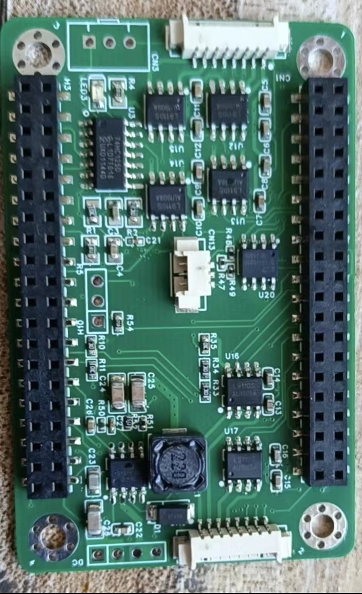
board (the robot's brain) uses the Liangshanpai development board, with the GD32F470 as its main control chip. The GD32F470 has rich peripherals and a 240MHz clock speed, potentially perfectly supporting the robot's various functions. An expansion board was added to the main control board to allow communication between the components on the main control board and the expansion board. The expansion board diagram is shown below.
The
robot uses 7 modules and 7 drive circuits. These modules include a stepper motor module, a bus servo module, a 0.96-inch OLED module, a MAX7219 dot matrix screen module, an HLK-V2.0 offline interface module, a WS2812 LED, an MPU6050 attitude sensor, a CAN bus circuit, a digital transistor drive circuit, a 5V power supply circuit, a buzzer drive circuit, an ADC battery detection module, a 9G servo drive, and a button detection module. Commonly used modules are not described here, as they are all from the Liangshanpai porting manual, and the programs are also copied from the source code. Let me focus on the parts not mentioned in the manual or that have undergone significant changes in the program:
1. Power Supply:
The power supply is the core of the robot. Without sufficient power, the robot cannot move. The 25 WS2812 5050 batteries used for the LED lights and dot matrix screen are very power-intensive, with the total current expected to reach around 1A. The SGM6132 power chip from Sanbang Microelectronics, used in the medicine delivery cart in the electronics competition, can reach up to 3A, and the voltage is adjustable. As shown in the diagram,

each module uses a 5V power supply, directly through R1, R2, R3, and C3. The output power voltage is adjusted. The 3.3V is output through the Liangshanpai development board. The power circuit is shown in the diagram.
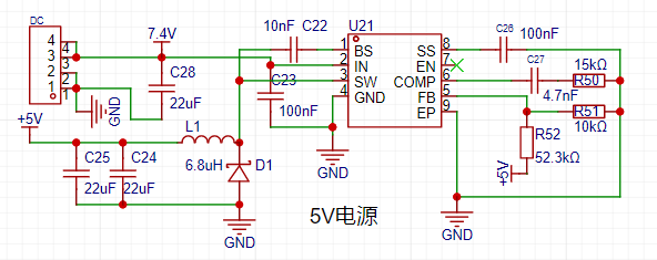
Two 18650 2000MA batteries are used, powered by a 16A switch to supply the power chip. See the diagram.

2. Bus Servo:
The main component of the robot is the servo motor. A UBTECH bus servo motor from UBTECH was used. This servo motor was a previously purchased second-hand unit; new bus servos are quite expensive. Ten servos were used. Eight were used for the leg joints, and two for weapon lifting. This bus servo used half-duplex serial communication. The Liangshan School (a computer programming language) can also configure the serial port for half-duplex communication, but I haven't done it before, so I don't know if it will work. I'll try it when I have time. For now, I'll use the circuit I've already tested, which will save time and avoid some detours. See the diagram.

The data for this bus servo is in the file below. You can download it if needed. Importantly, this bus servo sends hexadecimal data via serial port. I'll explain the data structure; following this structure will successfully control the servo. You can also refer to my program. The angle reading wasn't implemented; I don't know where the problem is. I'll investigate it later. The data structure is shown in the diagram.
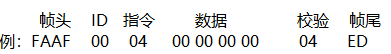
The check bit is the sum of ID + instruction + data.
3. 0.96-inch OLED screen.
The OLED screen circuit is nothing special. The key is that I ported the Arduino U8G2 library to the Liangshan School. This makes it very convenient to call U8G2 library functions. Software I2C driver was used. The LCSC development board's logo and battery level display were implemented using the U8G2 library functions, as demonstrated in the video. I originally wanted to create a cool menu, but didn't have time to debug the program; I'll add the menu items later.
3. MAX7219 Dot Matrix Screen Module:
The dot matrix screen only uses two 37*37 dot matrix panels, mainly displaying the robot's eye expressions.
4. Offline Voice Module:
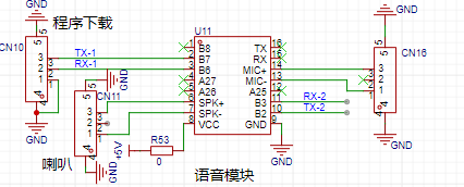
The voice module also uses the Hailink V2.0 module. This voice module is explained in detail in the smart curtain video tutorial. The voice module is quite useful. Five commands were created on the voice module for testing purposes. The circuit diagram is shown in the figure.
Robot Structure Description:
1. Servo Distribution ID Description

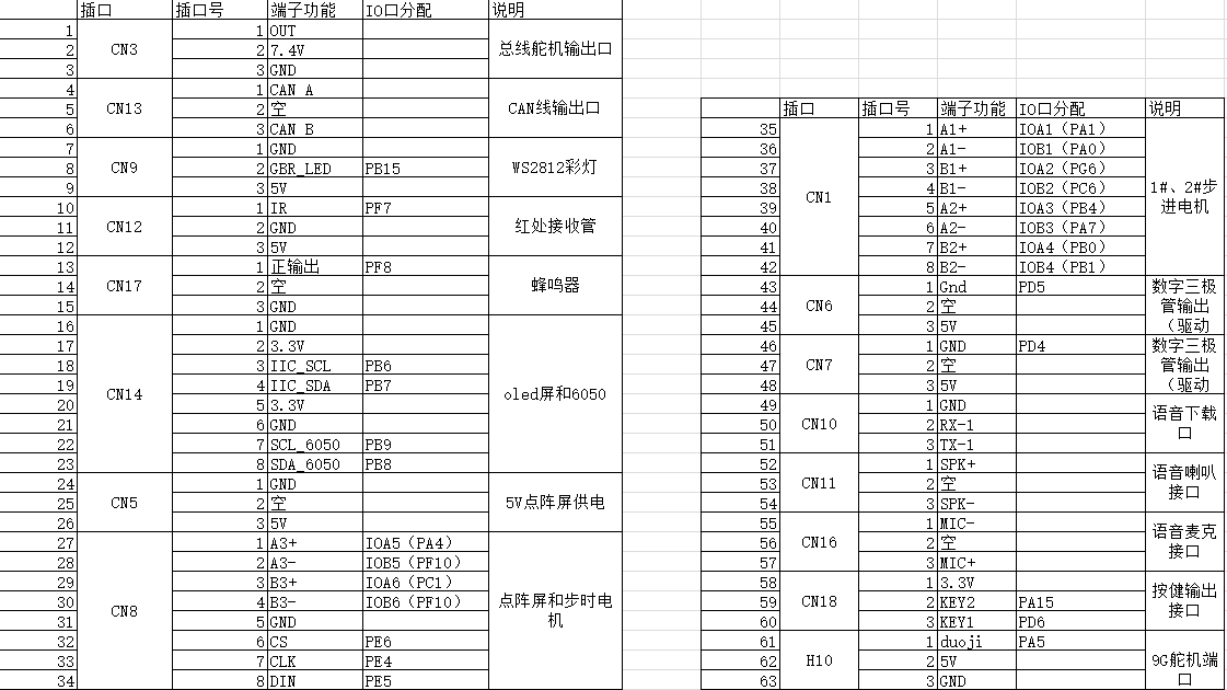
; 2. Robot Module Connection IO Table;
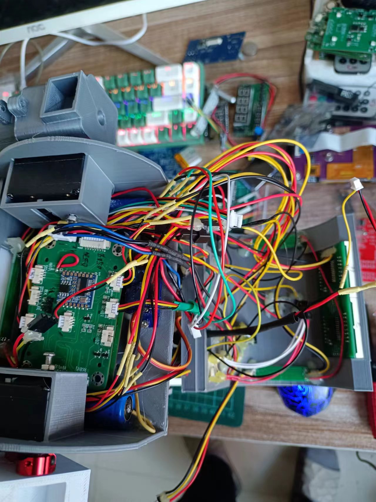
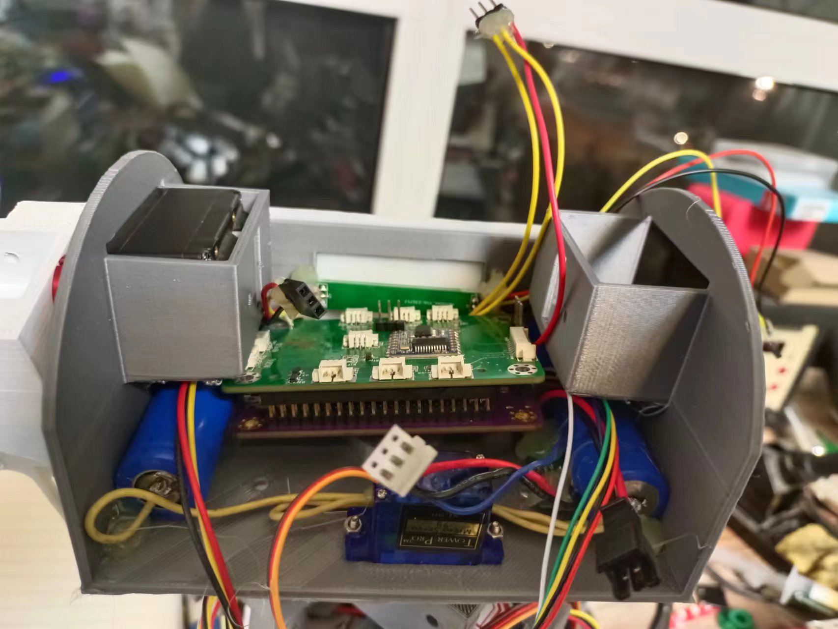
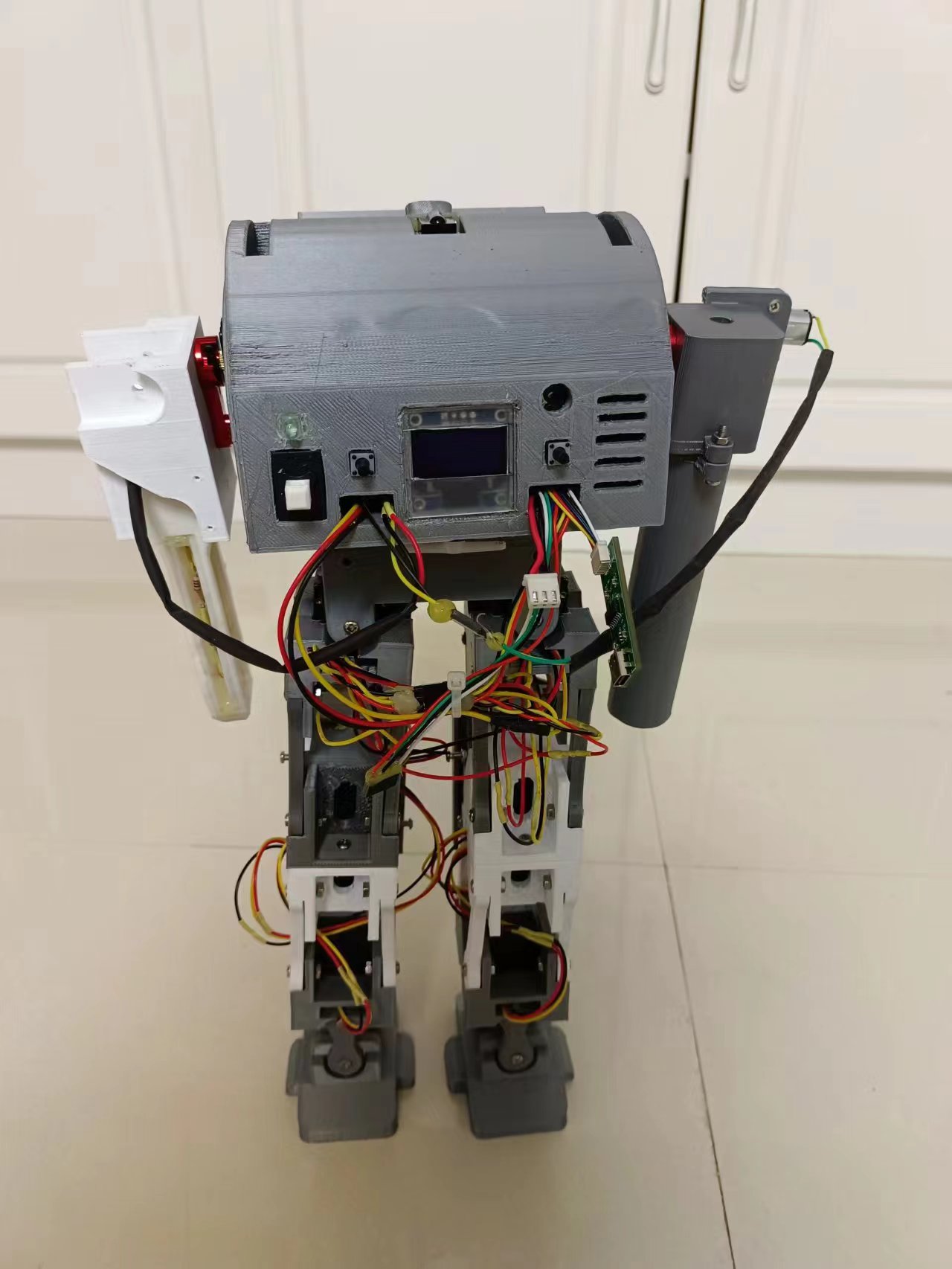
3. Robot Internal Images;
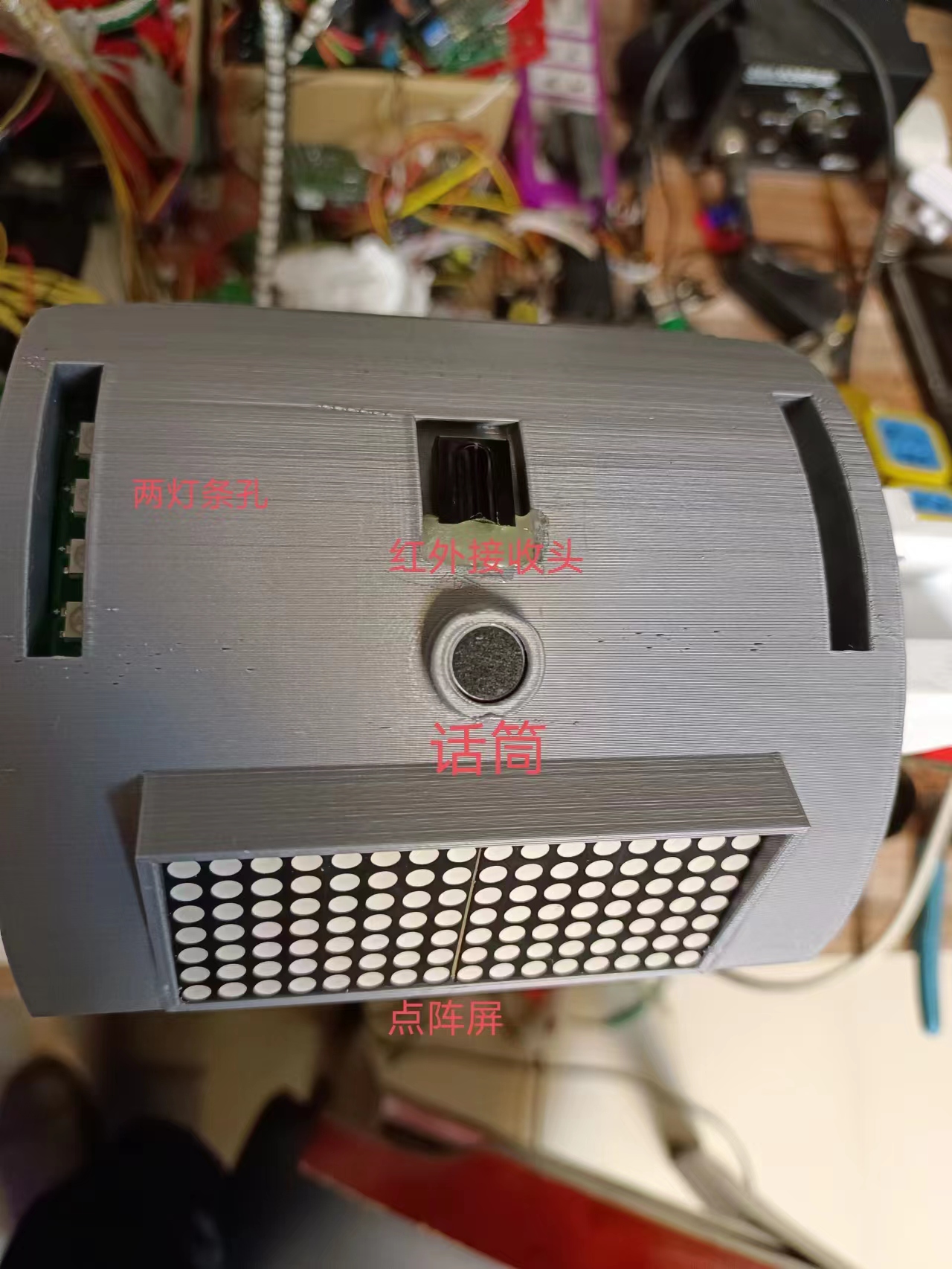
4. Component Positions in the Robot Head;

5. Full Robot Image

(Bilibili Video Address)
: [Combat Robot, main control uses Liangshanpai development board]. [https://www.bilibili.com/video/BV1VG41127Dq/?share_source=copy_web&vd_source=c4ac3c1e03440fed67ffc76ecb6d23d1](https://www.bilibili.com/video/BV1VG41127Dq/?share_source=copy_web&vd_source=c4ac3c1e03440fed67ffc76ecb6d23d1)
In summary
, bus servos have many advantages in use. Parallel operation saves on wiring and reduces the number of I/O ports required. Speed can also be controlled. Two months were spent completing the 3D model and debugging each module, but the program hasn't been properly debugged yet; the time allotted for program adjustments is too short. The walking posture is still not well-tuned; it's not as easy to adjust as I imagined. Further program updates will be made when time permits.


 京公网安备 11010802033920号

 EQRA12S1H-14.8456M TR


