0. Video Demonstration:
Click to watch the video
. 1. Project Function Introduction:
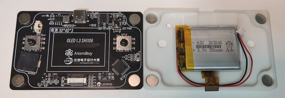
This is a credit card-sized mini game console based on Renesas MCUs, featuring a 128*64 resolution OLED screen, seven built-in mini-games, a rechargeable 350mAh lithium battery, an operating current of approximately 15mA, and a standby current of less than 100μA. It has an onboard DAP-LINK. Built-

in Games:
[x] Dinosaur Game [
x] Flappy Bird [x] Snake
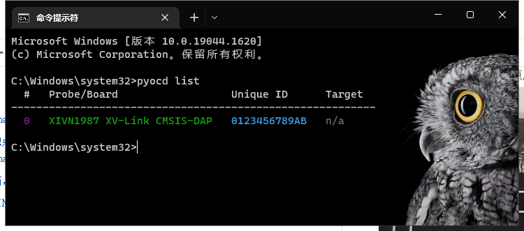
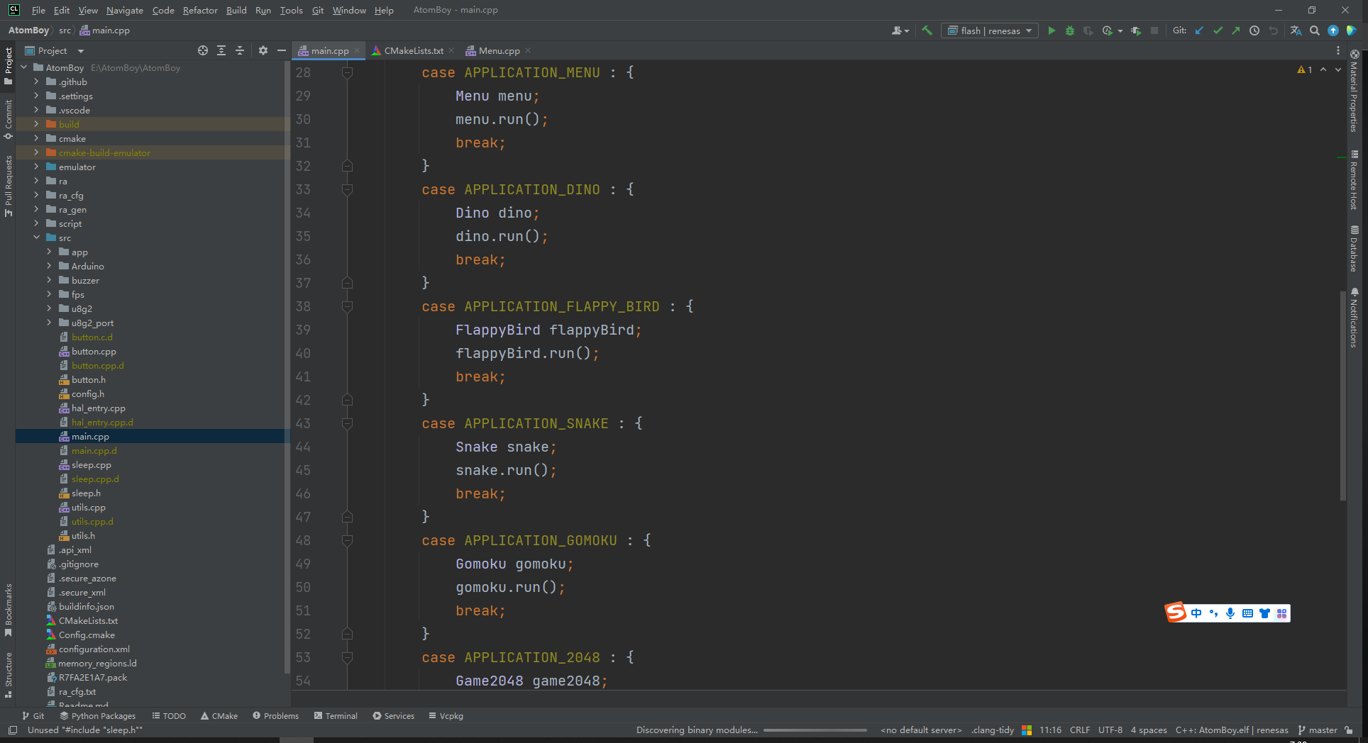
[ x] Gomoku [x] 2048 [x] Space Invaders [x] IKUN Function [x] Long Standby Time [x] Saves Game Progress in Standby [x] Onboard DAP-LINK 2. Project Attributes: First time publicly revealed, original work. 3. Open Source License: The GNU General Public License v3.0 4. Hardware: The hardware is relatively simple. Current from the USB port charges the lithium battery through an ETA6002 microcontroller. The ETA6002 also handles battery discharge, which is divided into two paths: one supplies the MCU (Microcontroller Unit) continuously; the other supplies the OLED and buzzer, with the MCU controlling the corresponding LDO (Logical Design Object) to disconnect their power supply in sleep mode. Additionally, the USB port powers and exchanges data with the onboard DAPLINK, which connects to the RA (Radar Interface) microcontroller via an SWD interface. The OLED connects to the MCU via SPI. The buzzer is controlled by a transistor, with the MCU outputting a 4000Hz PWM signal. | Main Chips | Functions | | --- | --- | | R7FA2E1A72DFL | Main control MCU, M23 core 48M, 16kb+64kb | | SH1106(CH1116) | 1.3-inch OLED screen | | ETA6002 | Lithium battery charging and discharging | | ME6211C33M5G-N | LDO | | CH32V203F6P6 | daplink | Magnets are attached to the four corners of the circuit board and the panel, respectively. The 3D printed interlayer is held in place by magnetic attraction. The magnetic design eliminates the need for screws on the outer shell and makes it easy to disassemble. Currently, the 3D shell cannot be exported; we are waiting for LCSC EDA to fix the bug. This bug is related to the side openings. Deleting the side openings allows exporting, but the USB port opening also disappears. The temporary solution is to manually sand it after receiving the 3D printed shell. It has been redrawn in SolidWorks; see attachment. 5. Software code acquisition: The code is hosted on GitHub: https://github.com/liux-pro/AtomBoy. Additionally, the DAPLINK firmware uses the firmware from @XIVN1987, whose open-source address is https://github.com/XIVN1987/DAPLink. This is the firmware for burning the onboard DAPLINK (this step can be skipped; the firmware in the attachment can be used directly). Download the DAPLINK code and compile the DAPLINK firmware using Mount River Studio. Download and install the WCH microcontroller programming tool . As shown in the image, select CH32 programming. In step six of the image, select CH32V203_DAPLink_aa14c15.hex from the attachment and short the DAP BOOT contact on the PCB. Connect the PCB to the computer via USB cable; the software will automatically burn the DAPLINK firmware. DAPLINK is now ready. Renesas RASC was used to generate project files based on CMake, which need to be compiled using ARM GCC. If you want to compile on your own computer, first install CMake and Ninja, then download ARM GCC and execute the following compilation command. Assuming the gcc toolchain is extracted to the root directory of drive D. ` cmake -B build -G Ninja -DCMAKE_FIND_ROOT_PATH=D:/gcc-arm-none-eabi-10.3-2021.10-win32/gcc-arm-none-eabi-10.3-2021.10/bin cmake --build build` For flashing the AtomBoy , since it has an onboard DAP-LINK, an external flashing device is not needed. Python 3 is pre-installed, and pyocd is installed via pip. After `pip install pyocd` , connect the USB to the computer and flash the program directly through the onboard DAP-LINK. `cmake --build build --target` For the flash emulator , to facilitate debugging and avoid re-flashing after each modification, an additional emulator was written so that most of the code can run on the computer. Install the msys2 environment (optional). Use msys2-mingw64 to execute `sed -i "s#mirror.msys2.org/#mirrors.ustc.edu.cn/msys2/#g" /etc/pacman.d/mirrorlist*`. Switch to a domestic mirror. Use msys2-mingw64 to execute `pacman -S mingw-w64-x86_64-SDL2` to install SDL2. Use msys2-mingw64 to execute `pacman -S mingw-w64-x86_64-toolchain`. `cmake make ninja git` to install the compiler, etc. `cd emulator && cmake -G Ninja -B build` `cd build && ninja ./AtomBoyEmulator.exe`. Use CLion . Using CLion can speed up development efficiency and avoid manually typing commands. If it's not clear, watch the video. The video demonstrates how to compile, flash, and use the emulator. https://www.bilibili.com/video/BV1Nx4y1X7iN/ Code Structure Directory ├─.github


│ └─workflows # Github Actions for automatically building hex files
├─cmake # CMake script, automatically generated by RASC
├─emulator # SDL-based simulator
├─ra # System code, automatically generated by RASC
├─ra_cfg # System code, automatically generated by RASC
├─ra_gen # System code, automatically generated by RASC
├─script # Linker script, automatically generated by RASC
└─src # Source code
├─app # Application
├─Arduino # Simulates Arduino
├─buzzer # Buzzer
├─fps # Controls screen refresh, provides system tick
├─u8g2 # u8g2 source code
└─u8g2_port # u8g2 port
└─main.cpp # Main function entry point
└─button.cpp # Button scanning
└─sleep.cpp # The basic structure of the low-power mode
RASC-generated
code is generated using RASC. This project can be imported via RASC to configure the pins, clock, peripherals, etc. of the Renesas MCU. The compilation process does not require RASC involvement.
The CMake files generated by the current version of RASC (v4.5) have various issues, which have been corrected in this project; please be aware of this when generating new projects.
[https://github.com/renesas/fsp/issues/256](https://github.com/renesas/fsp/issues/256
) [https://github.com/renesas/fsp/issues/280](https://github.com/renesas/fsp/issues/280) The overall architecture
uses a timer to generate a 1ms clock source, updating the flag bit approximately every 16ms. The main loop polls the flag bit and refreshes the frame, ensuring a stable frame rate when sufficient computing power is available.
The OLED screen is driven using U8G2, and the porting uses hardware SPI.
Each button is directly connected to a GPIO, with internal pull-up enabled. The button state is updated with the screen refresh; a low-level transition of the GPIO indicates a button press. There is no debouncing. In the game, a scan function is called every frame to update the button state.
Each game (including the main menu) is considered an app. The main loop determines which app to enter based on the variable `nextApplication`, defaulting to the main menu.
Each app implements the `run` abstract method, internally using u8g2 to manipulate the screen and implement game logic. After the `run` method returns, it re-enters the main loop.
In the menu app, after selecting an item, `nextApplication` is modified and then returned; the next loop enters the selected game based on the modified `nextApplication`.
The power button implements short press and long press; anything over 500ms is considered a long press. A long press restarts the system. A short press enters low-power mode, and pressing the power button again wakes the system.
Entering low-power mode via the `goSleep` function disables irrelevant LDOs. Upon waking, the OLED is restored, the buzzer is powered, and the OLED is reinitialized to continue executing the current logic. After
5 minutes of inactivity, it automatically enters low-power mode.
Overall, clock stability requirements are not high, so a built-in oscillator is used.
Global variables are avoided within each app as much as possible. Heap memory is not enabled; 14000kb of stack memory is allocated.
Note: If your project involves software development, please upload the corresponding project source code as an attachment. This section allows you to detail your software flowchart, functional module diagram, explanations or popular science explanations of relevant algorithms, source code structure, compilation environment setup and configuration, source code compilation methods, and program burning methods. We recommend presenting your ideas in a visually appealing format with illustrations.
6.
Most components in the BOM list can be purchased from the LCSC online store. All components in JLCSC EDA have been standardized and linked to their LCSC online store serial numbers. Links to other accessories are provided below.
| Components | Specifications | Purchase Link | Notes |
| --- | --- | --- | --- |
| OLED Screen | 16PIN White Backlight | https://item.taobao.com/item.htm?id=661586745978 |
| Lithium Battery | 303040-350mAh | https://item.taobao.com/item.htm?id=578342493353 | Ask the seller to include a 1.25mm forward plug |
| Joystick | 10109MM | https://item.taobao.com/item.htm?id=595134302480 | Buy keycaps as well; buy two sets |
| CH32V203F6P6 | CH32V203F6P6 | https://item.taobao.com/item.htm?id=689965812965 | |
Magnets | 50 pieces 8*2mm | https://item.taobao.com/item.htm?id=44141739720 | High temperatures will demagnetize the magnets |
7. Competition LOGO verification

8. Demo your project and record it as a video to upload
https://www.bilibili.com/video/BV1Th4y117CR/
9. Powered by open-source software Open source links
OLED driver https://github.com/olikraus/u8g2 DAPLink firmware https://github.com/XIVN1987/DAPLink Gomoku AI algorithm https://gitlab.com/nowozin/maxigoarduboy ikun animation compression algorithm https://www.quicklz.com/ (Official website is inaccessible) Dinosaur game assets https://github.com/chromium/chromium Renesas SDK https://github.com/renesas/fsp 10. Optimizable parts
The components were rearranged to eliminate components within 1mm of the battery, reducing assembly difficulty.
The USB port is now located on the left or right side, instead of the top or bottom long edges. The existing Type-C port area is too thin and lacks strength. A small iron rod could be embedded for reinforcement.
The adhesive used for the panel magnets has been replaced with AB glue, as the included 3M adhesive is insufficient for strong magnets.
The joystick is too small, making directional control difficult.
The battery level and charging status are not displayed.


 京公网安备 11010802033920号

 1.5KE62CE3/100


