Output current: 3A
adjustable; soft-start function
; 100mΩ internal power MOSFET switch
with low ESR; output ceramic capacitor ensures stable operation with
efficiency up to 95%
; 20μA shutdown mode;
385kHz fixed frequency
over-temperature shutdown protection; cycle-by
-cycle overcurrent protection;
wide operating input voltage range: 4.75V to 28V
; adjustable output voltage from 1.22V
; undervoltage lockout (UVLO) protection;
uses an 8-pin SOIC package;
tested without issues with 24V, 3A input load; heat sink required for long-term full-load operation.

MP1593 Datasheet.pdf
PDF_MP1593DN step-down module.zip
Altium_MP1593DN step-down module.zip
PADS_MP1593DN step-down module.zip
BOM_MP1593DN step-down module.xlsx
95785
DRV8313 low-power FOC driver board
Low-power FOC driver board based on DRV8313
For those interested in learning FOC, you can check out the repository at https://gitee.com/HappyAncia. It contains FOC code I wrote based on this driver board and a found STM32F103C8T6 minimum system board. Feel free to learn together!
Closed-loop position FOC.mp4
Closed-loop current FOC.mp4
PDF_DRV8313 Low-Power FOC Driver Board.zip
Altium_DRV8313 low-power FOC driver board.zip
PADS_DRV8313 low-power FOC driver board.zip
BOM_DRV8313 Low Power FOC Driver Board.xlsx
95786
Electronic Butterfly
Based on the principle of free access, an improved "breathing" electronic butterfly has been created, capable of blinking without any code. Original author: [Xiao Jun Chou], LCSC Open Source Platform.
I.
The overall schematic diagram of the LED blinking device is as follows:
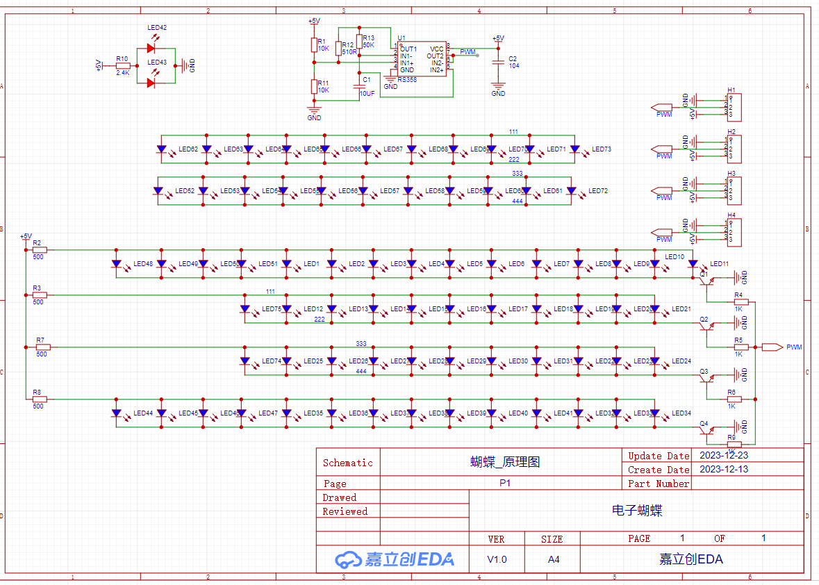
Working principle: The operational amplifier U1 continuously charges and discharges capacitor C1, resulting in a triangular wave (red waveform) as shown in the diagram. This triangular wave is then used to control the switching on and off of the transistor, thus achieving LED blinking.
The blinking speed is determined by the capacitor's charging and discharging cycle, which is three times the time constant (it is generally believed that the capacitor is fully charged or discharged after three times the time constant).
Therefore, adjusting the LED blinking speed only requires changing the values of R13 and C1. Try it out yourself!
PS: The PWM logo on U1 is just a random name I made up; the actual waveform is also a triangular wave, but I added a voltage follower stage to increase the load-driving capability of the triangular wave. For

PCB soldering, refer to the original author's instructions; I'm too lazy to write it out. II. The schematic diagram of
the PCB support bracket is as follows: Working principle: H1 is a 5V external power socket (why leave a socket? Because freebies make me happy); an additional Type-C interface is reserved, but only the 5V power supply pin is connected. Either power interface can be selected, or both can be plugged in simultaneously. There is a diode for reverse polarity protection, so don't worry. PCB Soldering Instructions: III. Material Preparation: 1. All electronic components, sourced from [company name] for free; 2. PCB, sourced from JLCPCB for free; 3. Soldering tools, sourced from [company name] for free; although I also have some in stock, getting things for free makes me happy (doge emoji for protection). IV. See attached project files for physical demonstration . Video on Bilibili: https://www.bilibili.com/video/BV1he41127hb/?vd_source=bc354c22d786c4e0b934a0e443fd6509


Breathing Electronic Butterfly [Project File].epro
PDF_Electronic Butterfly.zip
Altium_ElectronicButterfly.zip
PADS_Electronic Butterfly.zip
BOM_Electronic Butterfly.xlsx
95787
Intelligent LED Strip System - Aurora
The ESP32-based smart light strip system, based on Blinker, supports: Xiao Ai voice assistant, flowing light effects, weather and time display, sedentary reminder, and computer shutdown.
This smart light strip system, based on ESP32 and Blinker, supports: Xiao Ai voice assistant, flowing light effects, weather and time display, sedentary reminder, and computer
shutdown. The project is open-source at https://github.com/bszydxh/smart_light_system
and includes an Android and PC client.
This board is only a data board and cannot be used to directly drive the light strip.
Video 1 demonstrates the flowing light effects;
Video 2 demonstrates computer-controlled light strip operation.
208168212-7c93ab88-0b14-446b-8acc-c92a9ee06c3b.mp4
208168375-cefdf474-2f2c-4264-8bb8-2c2823d160cd.mp4
PDF_Intelligent LED Strip System - aurora.zip
Altium Smart LED Strip System - aurora.zip
PADS Smart LED Strip System - aurora.zip
BOM_Intelligent LED Strip System-aurora.xlsx
95788
electronic


 京公网安备 11010802033920号

 19-002-107


