Project Name: ESP32-Type-C Ammeter (with PD Spoofing Function)
Project Description:
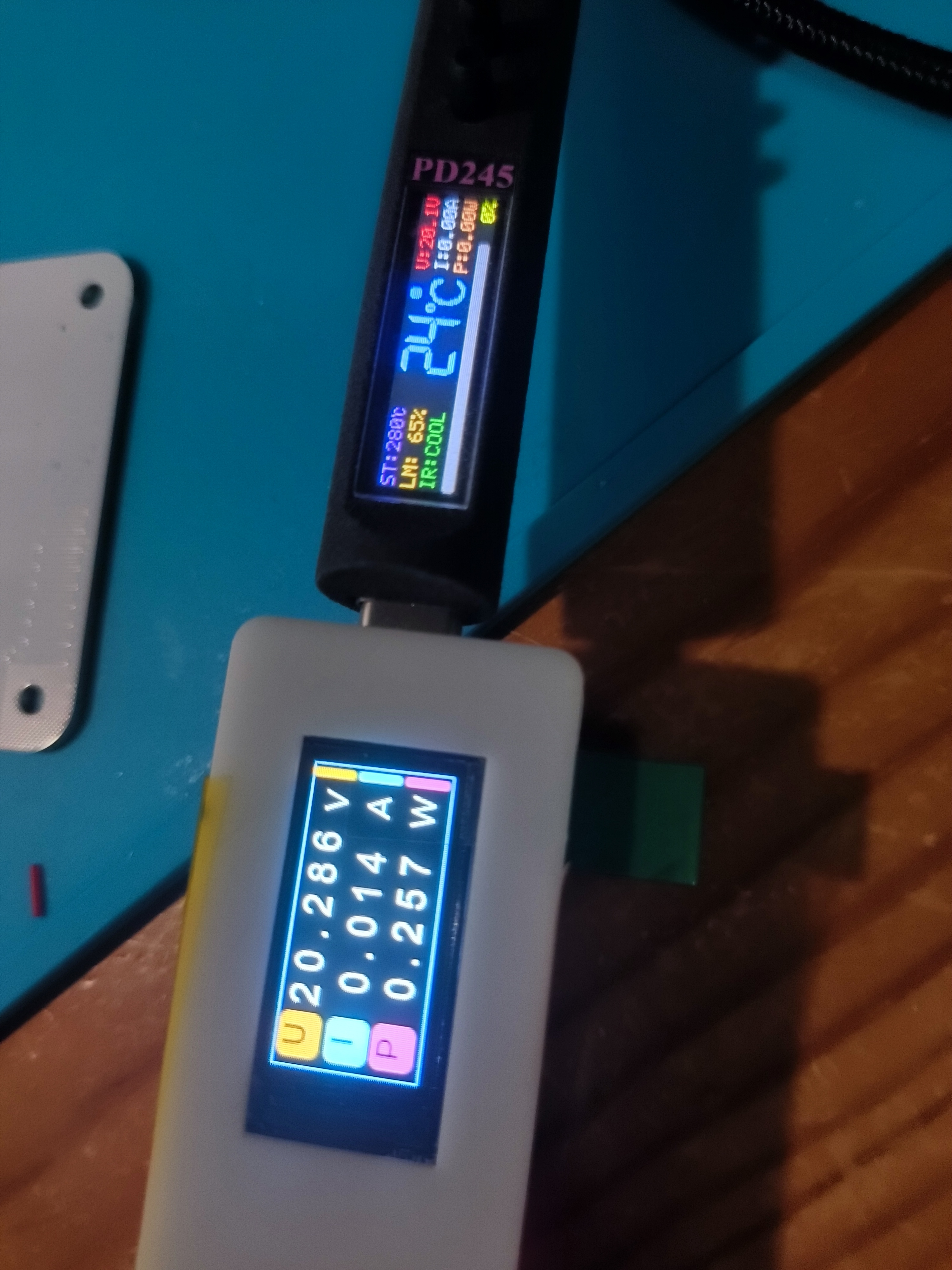
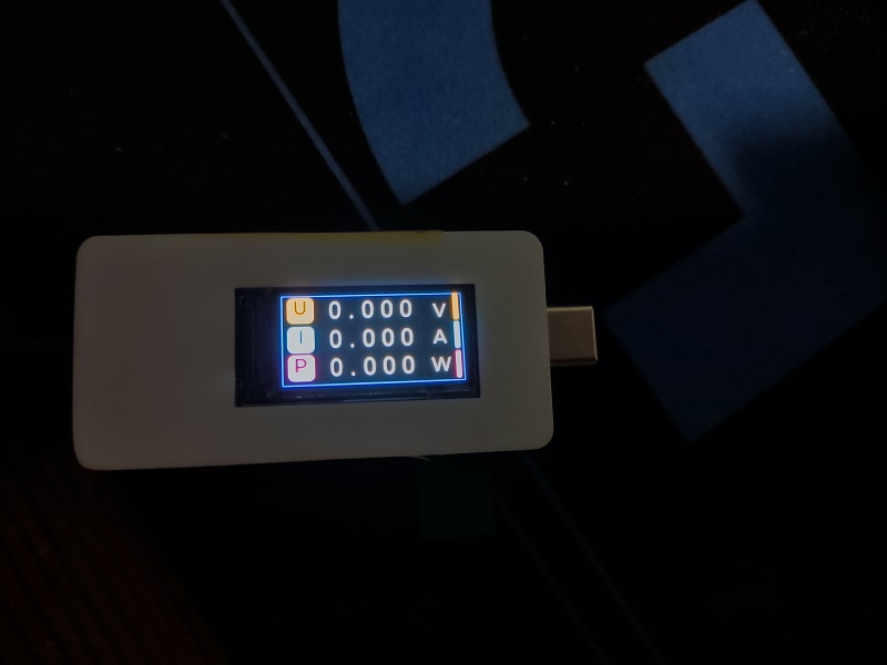
This project is a Type-C ammeter based on the ESP32 microcontroller, using a button and a CH224 chip for PD (Power Delivery) spoofing. It implements PD protocol power management through the Type-C interface, monitors current and voltage in the circuit in real time, and displays the data on a 0.96-inch TFT screen. The project integrates a TI INA226 sensor for high-precision current and voltage acquisition, providing accurate reference for power management of USB devices.
Hardware Components:
ESP32 Microcontroller:
- Model: ESP32S3R8N8
- Provides Wi-Fi and Bluetooth functionality, with rich peripheral interfaces.
- Communicates with the INA226 sensor via I2C and drives the TFT screen via SPI.
TFT Screen:
- Size: 0.96 inches
- Interface: SPI
- Function: Displays parameters such as voltage, current, and power.
TI INA226 Current Sensor:
- Function: Used for accurate measurement of current and voltage.
- Features: Supports I2C communication, built-in 10 milliohm sampling resistor.
USB Type-C Interface:
- Connects devices via the USB-C interface for current and voltage monitoring, and supports PD protocol power management.
CH224 PD Spoofing Chip:
- Function: Triggers the PD protocol, simulating device PD fast charging voltage selection.
- Features: Can be triggered by a button to select different voltage levels, spoofing the device to output a specified voltage (e.g., 5V, 9V, 12V).
Buttons:
- Two physical buttons are designed:
1. Voltage Level Selection: Used to select different voltage levels for the PD fast charging protocol.
2. Display Mode Switching: Used to switch the content displayed on the TFT screen (e.g., display modes for different parameters such as voltage, current, and power).
Working Principle:
Data Acquisition: The INA226 sensor communicates with the ESP32 via I2C to acquire voltage and current data in the circuit in real time.
PD Spoofing Function: Through the PD spoofing function of the CH224 chip, users can select different voltage levels by pressing a button to simulate the device's request for a fast charging power source.
Data Processing: The ESP32 processes the acquired data and displays the current voltage, current, power, and other information in real time on the TFT screen.
Type-C Interface Monitoring: Power and data transmission are handled via the Type-C interface, monitoring the current and voltage passing through this interface.
Project Features:
PD Spoofing Function: Using the CH224 chip, a button allows for PD protocol fast charging voltage selection, enabling users to choose different charging voltages for monitoring.
Button Interaction: Two buttons switch between PD voltage levels and TFT screen display modes, increasing user interaction flexibility.
High-Precision Current and Voltage Monitoring: The TI INA226 sensor ensures high-precision current and voltage measurements.
Real-Time Display: Power, current, and voltage information are intuitively displayed on a 0.96-inch TFT screen.
Application Scenarios:
USB PD Charger Testing: Can be used to test whether USB chargers supporting the PD protocol correctly output the target voltage.
Electronic Device Power Consumption Monitoring: Monitors the power consumption of various PD devices.
Development and Debugging: Suitable for developing and debugging electronic devices requiring PD spoofing functionality, facilitating verification of power consumption performance under different voltages.
By integrating the PD spoofing function, this project not only monitors current and voltage but also has PD protocol voltage selection capabilities, suitable for scenarios requiring fast charging management.
firmware.bin
PDF_ESP32-Typec Ammeter.zip
Altium_ESP32-Typec Ammeter.zip
PADS_ESP32-Typec Ammeter.zip
BOM_ESP32-Typec Ammeter.xlsx
91536
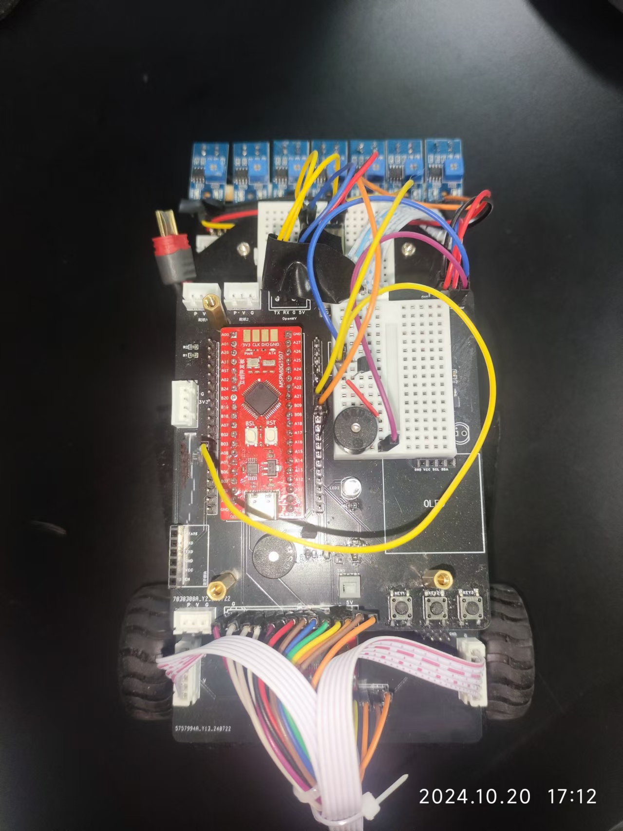
An autonomous driving vehicle based on the Earth Spirit Star MSPM0G3507
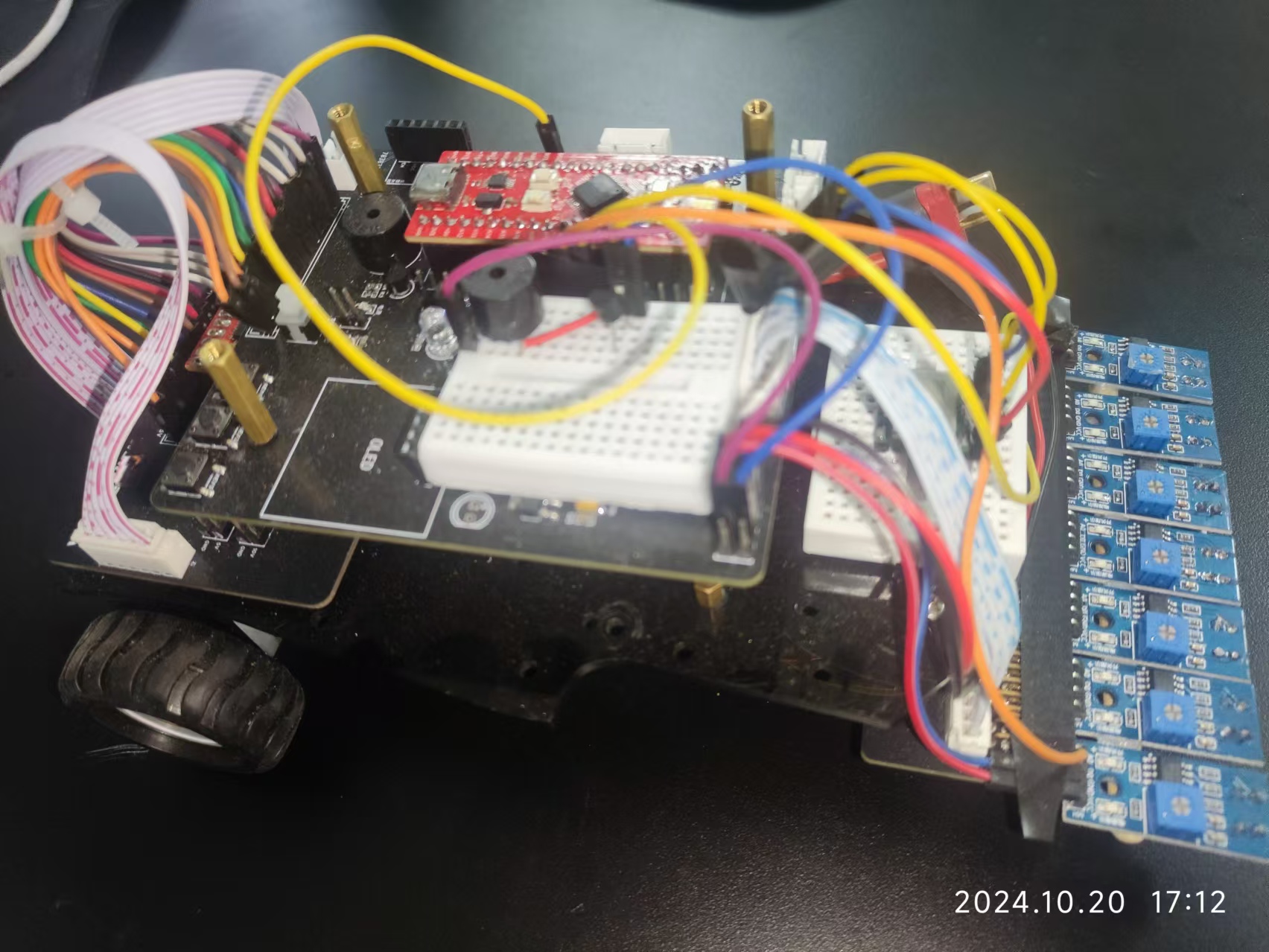
This project, based on the LCSC MSPMOG3507 development board, fabricated a car's power supply board, main control board, and tracking board, suitable for the 2024 Provincial Electronics Competition, Problem H.
I. Awards
This work won the second prize in the Jiangxi Division of the 2024 National Undergraduate Electronic Design Contest.
II. Topic Requirements

III. Design Summary
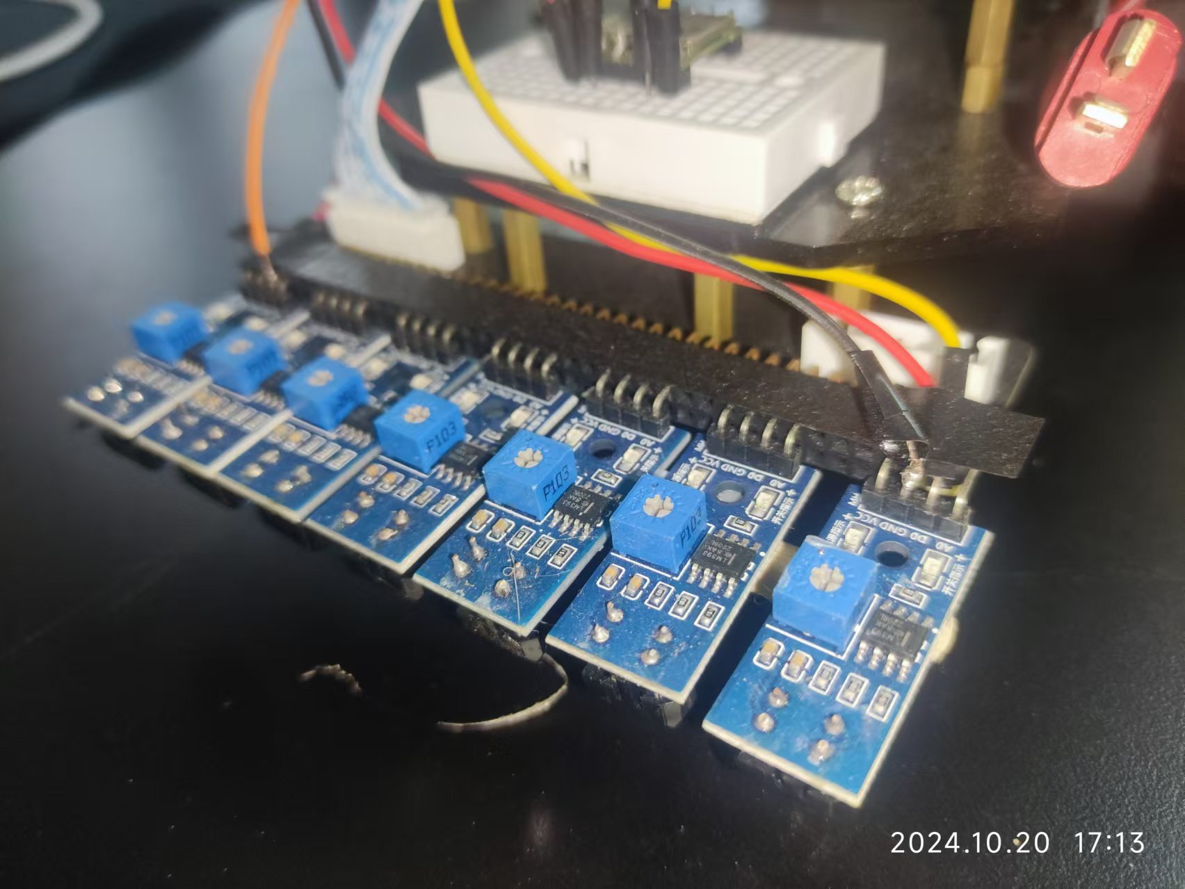
This work adopts a modular design. The control board uses the LCSC development board MSPMOG3507 as the main controller, integrating common modules such as OLED display module, buttons, and buzzer; the power board uses two adjustable switching power supplies to step down the 12V power input to 10V and 5V, and uses a TB6612 motor driver to drive two MG310 motors; the tracking board simply places two rows of corner headers, and infrared tracking or grayscale sensors can be freely added as needed.
IV. Physical Demonstration

V. Precautions
For better results, an external Witt serial port gyroscope was also connected.
VI. Demonstration Video
See the attached video for the demonstration video.
VII. Code
The software part of this project was developed using the CCS Theia platform. The program was burned using the Type-C port on the Dimengxing development board. The burning tool was UniFlash.
Part of the code is given below; the complete code is in the attached file. Car_v4.1
{
SYSCFG_DL_init(); // Chip initialization
DL_TimerG_startCounter(Motor_PWM_INST); // Motor PWM enable
NVIC_EnableIRQ(TIMER_Encoder_Read_INST_INT_IRQN); // Encoder timer enable NVIC_EnableIRQ(
GPIO_MULTIPLE_GPIOA_INT_IRQN); // GPIOA interrupt enable
DL_Timer_startCounter(TIMER_Encoder_Read_INST); // Start encoder timer
NVIC_ClearPendingIRQ(UART_0_INST_INT_IRQN); // Clear UART0 interrupt flag
NVIC_EnableIRQ(UART_0_INST_INT_IRQN); // Enable UART0 interrupt
NVIC_ClearPendingIRQ(UART_1_INST_INT_IRQN); // Clear UART1 interrupt flag
NVIC_EnableIRQ(UART_1_INST_INT_IRQN); // Enable UART1 interrupt
NVIC_EnableIRQ(ADC12_1_INST_INT_IRQN); // Enable ADC interrupt
OLED_Init(); // Hardware I2C-OLED initialization
OLED_Clear(); // OLED screen clear
control_PID_Init(); // PID controller initialization
motor_Direction_Set(0,0); // Motor initialization
tracking_Init(); // Tracking initialization
/* Task system time initialization */
current_time = Get_Tick();
uint32_t last_task01_time = current_time;
uint32_t last_task02_time = current_time;
Mode = 0; //test
while (1)
{
control_Proc(); //main control process
display_Remind_Proc(); //audio-visual prompt process
com_UART0Receive_Handle(); //data processing after the UART0 data packet reception success flag is set
current_time = Get_Tick();
/*button process*/
if(current_time - last_task01_time >= TASK_BUTTON_DELAY)
{
// TODO Task01
last_task01_time = current_time;
button_Proc();
}
/*OLED process*/
if(current_time - last_task02_time >= TASK_OLED_DELAY)
{
// TODO Task02
last_task02_time = current_time;
display_OLED_Proc(display_OLED_mode);
}
}
}
Demo video.mp4
Car_v4.1.zip
PDF_Autonomous Driving Car Based on MSPMOG3507.zip
Altium-based autonomous vehicle (based on the MSPMOG3507).zip
PADS_Autonomous Driving Car Based on MSPMOG3507.zip
BOM_Automatic Driving Car Based on Earth-based MSPM0G3507.xlsx
91537
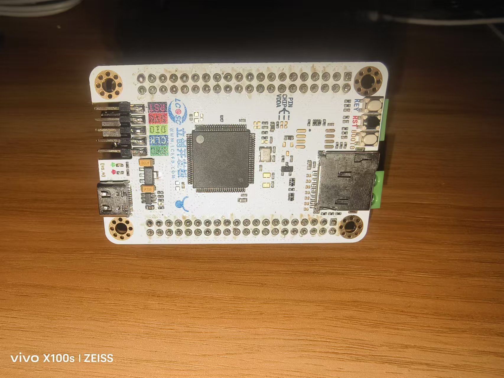
A simple waveform generator based on LCSC SkyStar
Using LCSC SkyStar as the main controller, an extended version was designed to support the generation of waveforms such as sine waves, square waves, triangle waves, and noise waves of different frequencies.
Output channels: 2 (independently controlled)
; Duty cycle: 0-100%;
Output range: -3.3V to +3.3V.
To optimize cost, parameters such as frequency and duty cycle are all software-controlled. Amplitude is controlled via a PCM5102APW chip. Multiple expansion options are available for ease of use.
Two rotary encoders are used to adjust various parameters, including waveform type, duty cycle, amplitude, and frequency. A 0.96-inch OLED screen displays parameter information. The expansion board provides various output interfaces for convenient use.
Simple Waveform Generator Demonstration Video.mp4
Simple waveform generator source code.zip
PDF_Simple Waveform Generator Based on LCSC SkyStar.zip
Altium - A Simple Waveform Generator Based on LCSC Skystar.zip
PADS - A Simple Waveform Generator Based on LCSC Skystar.zip
BOM_Simple Waveform Generator Based on LCSC SkyStar.xlsx
91538
Traffic lights at an intersection, first association training session
A very simple PCB for a traffic light at an intersection.
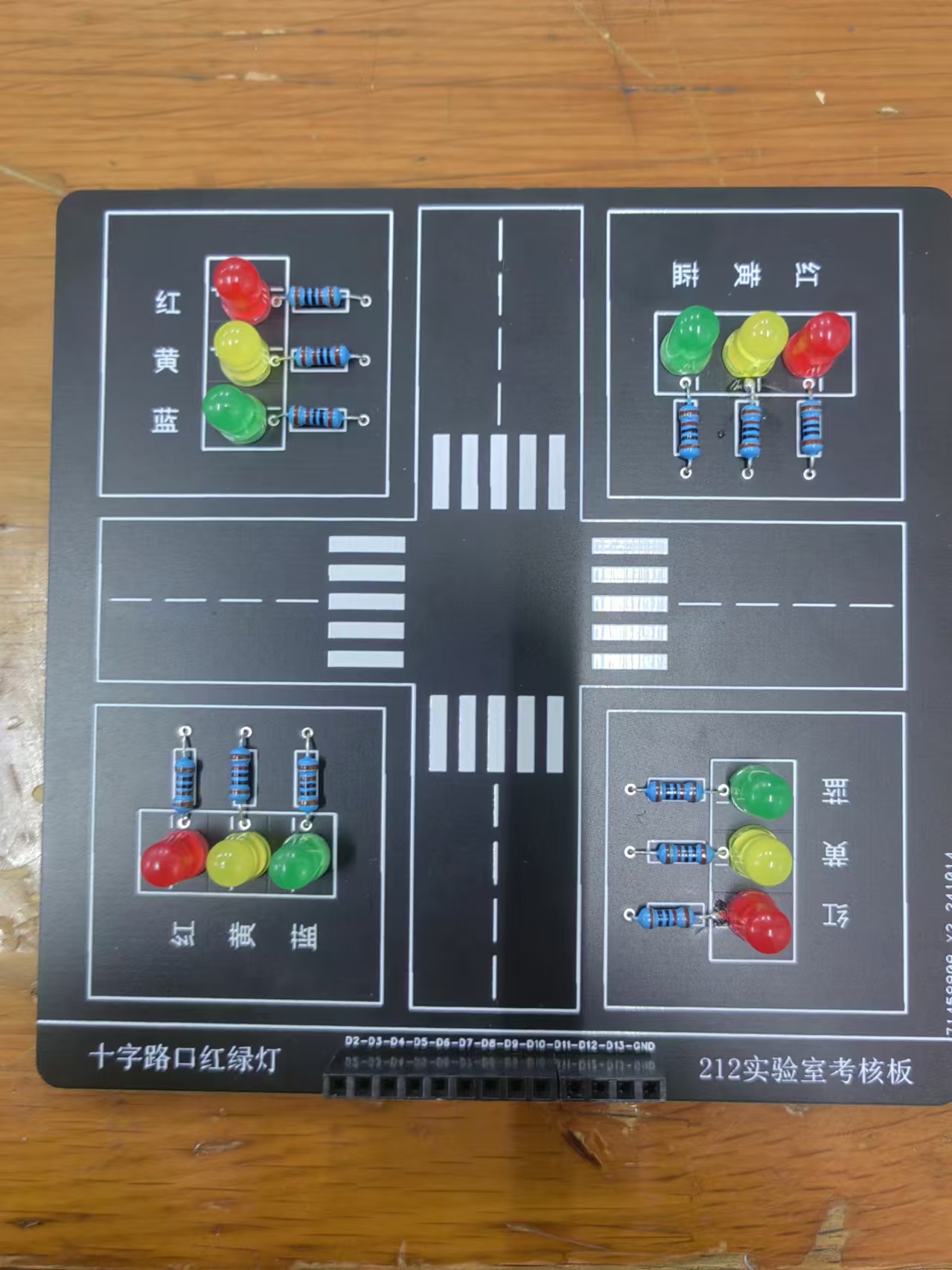
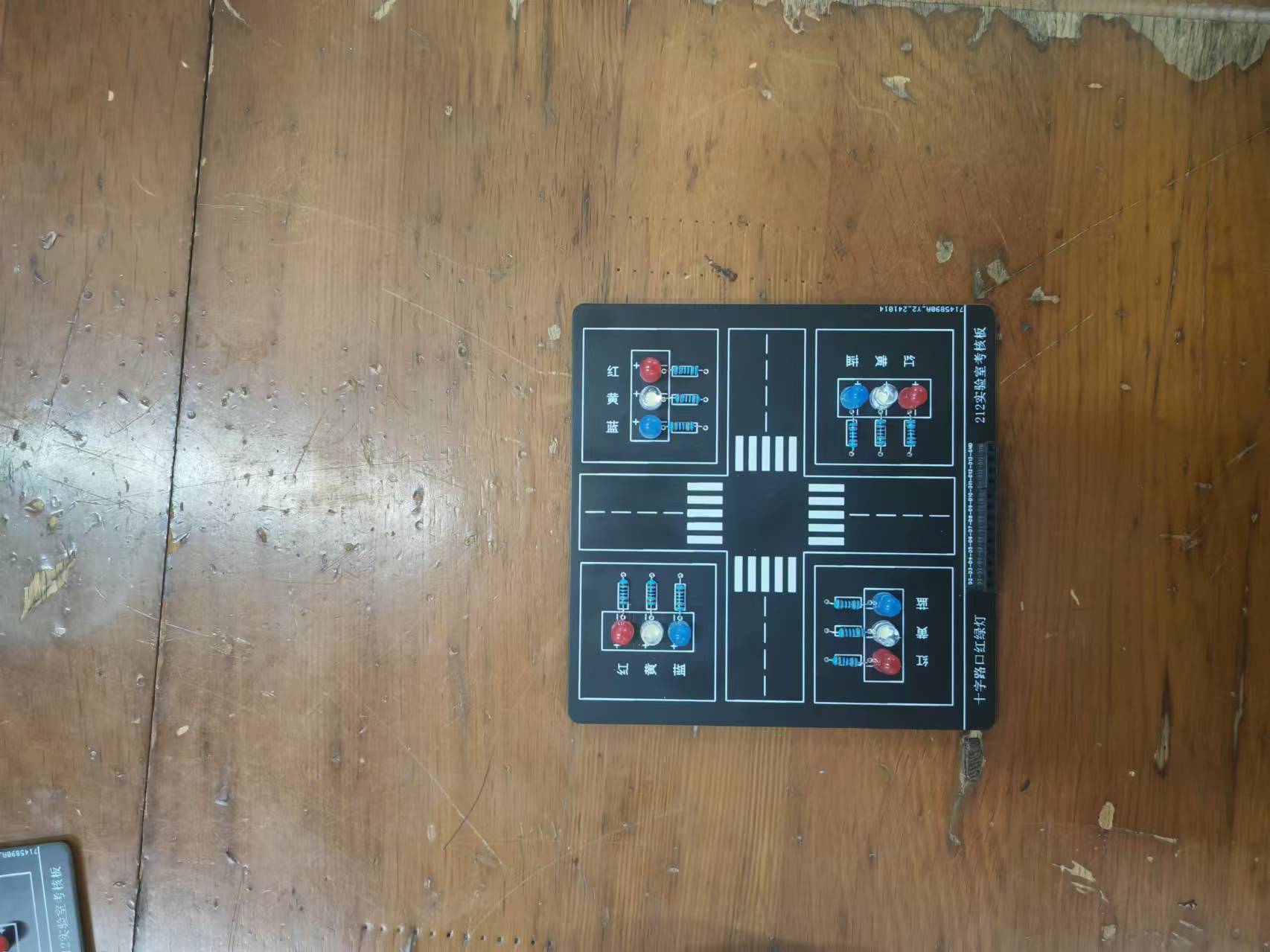
This is a training program for new students at Shenyang University of Technology. It's simple and easy to learn, using a microcontroller.
After connecting the microcontroller to this PCB, it controls the LEDs by outputting high and low levels. The soldering is simple and the cost is very low, making it suitable for new students. The Bill of Materials
(BOM) is not included; it only includes a few LEDs and resistors.
PDF_Traffic Lights at Crossroads, First Association Training.zip
Altium_Traffic Lights at Crossroads, First Association Training.zip
PADS_Traffic Lights at Intersections, First Association Training.zip
BOM_Traffic Lights at an Intersection, First Association Training.xlsx
91539
electronic


 京公网安备 11010802033920号

 820NQB7ES3R


