The video at https://www.bilibili.com/video/BV1uLCdYpESQ/
is inspired by the halo effect of Alice Tendo from the anime "Blue Archives".

The board has no other components, only LEDs.
Considering the soldering difficulty and price of the LEDs, 0805 SMD LEDs (ice blue, 100 for less than 5 RMB including shipping) were chosen.
A total of 45 LEDs were used, all manually soldered with a soldering iron using "Soldering Emperor". If possible, apply for SMT (note the LED color selection when matching components).
The size should be kept within 10*10cm. JLCPCB can make free samples (white solder mask recommended).
A lanyard hole is provided at the top, so it can be used as a hanging accessory without soldering LEDs
. There is a relatively wide area in the middle, which might be able to fit a small DC-DC converter (too lazy to bother with that
). (See original image: HALO一覧 - ブルーアーカイブ(ブルアカ)攻略Wiki)
PDF_Azure Archives Alice Halo.zip
Altium_Azure Archives Alice Halo.zip
PADS_Azure Archives Alice Halo.zip
BOM_Azure Archives Alice Halo.xlsx
91565
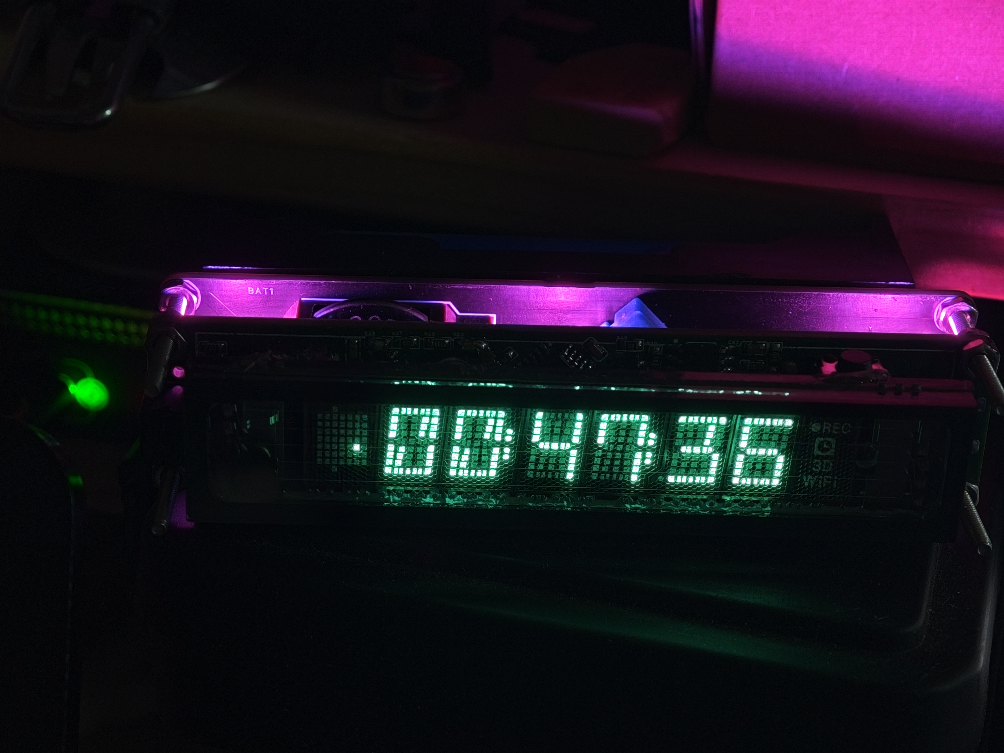
VFD Clock | Offline Timekeeping | Desktop Decoration
A VFD clock based on STM32F103C8T6 and FreeRTOS, VFD model 7-BT-317NK.
VFD-Clock Source Code and Firmware Introduction
Based on STM32F103C8T6 and FreeRTOS: This is a VFD clock based on STM32F103C8T6 and FreeRTOS, using fluorescent tubes to indicate the time. It runs completely offline with an annual error of less than 1 minute. User Guide: Solder the PCB , use STM32CubeProgrammer to burn the pre-compiled program, connect via USB, and use a time synchronization tool to synchronize the computer time. Component purchases should refer to the schematic diagram; the BOM may be incorrect . Left and right buttons switch pages. Long press the left button to turn the RGB lights on/off; long press the right button to toggle display brightness (7 levels). Hardware: STM32F103C8T6 main controller, 7-BT-317NK fluorescent tube, WS2812-LED light, push-button switch, buzzer , switching power supply, 18650 lithium battery, DHT11 temperature and humidity sensor, DS3231 real-time clock. Software: VSCode EIDE, STM32CubeMX, STM32CubeProgrammer. The software is not yet fully complete; issue and PR submissions are welcome. Thanks to XACT for the negative voltage Cuk power supply design and to Saisaiwa for the VFD segment code driver code design.
PDF_VFD Clock_Offline Timekeeping_Desktop Ornament.zip
Altium_VFD Clock_Offline Timekeeping_Desktop Ornament.zip
PADS_VFD Clock_Offline Timekeeping_Desktop Ornament.zip
BOM_VFD Clock_Offline Timekeeping_Desktop Ornament.xlsx
91566
The ultra-small ESP32C3mini development board is recommended for beginners (verified).
This ultra-compact ESP32C3 development board, redesigned for the new smart socket, is being shared separately. It allows direct programming via a Type-C connector (but the serial chip has been removed, so debugging is not supported). It features 8 interfaces.
Risk Warning:
No
project background
. The previous project I shared was a metering socket based on ESPhome (ESP8266). Recently, I modified an ESP32C3 to accept the Matter protocol, and also redesigned the original through-hole board (because I'm bad at soldering). I changed it to a 2.54mm pin header, which can accept both standard pin headers and bent pins, allowing the chip to stand upright!
Programming: Direct USB-C connection. The advantage is simple soldering; the disadvantage is that it can only program, not debug.
LED indicator: There is a 3.3V LED that lights up when powered on.
Pin header: 3.3V, 5V, GND, and 5 GPIOs are brought out. TXD and RXD are not brought out here; you can modify them if needed. Purpose:
I think this is quite beginner-friendly, allowing you to understand the basic routing design of ESP32C3. It also uses 0603 package resistors and capacitors, which are easy to solder. The only two difficult parts for beginners are soldering the Type-C and C3 connectors, but this is a necessary step, so just keep playing around with it.
PS1 There are some small ESD and surge protectors next to the USB port. I haven't investigated the specific principles, but everyone seems to have them (including those on LCSC's C3 development board).
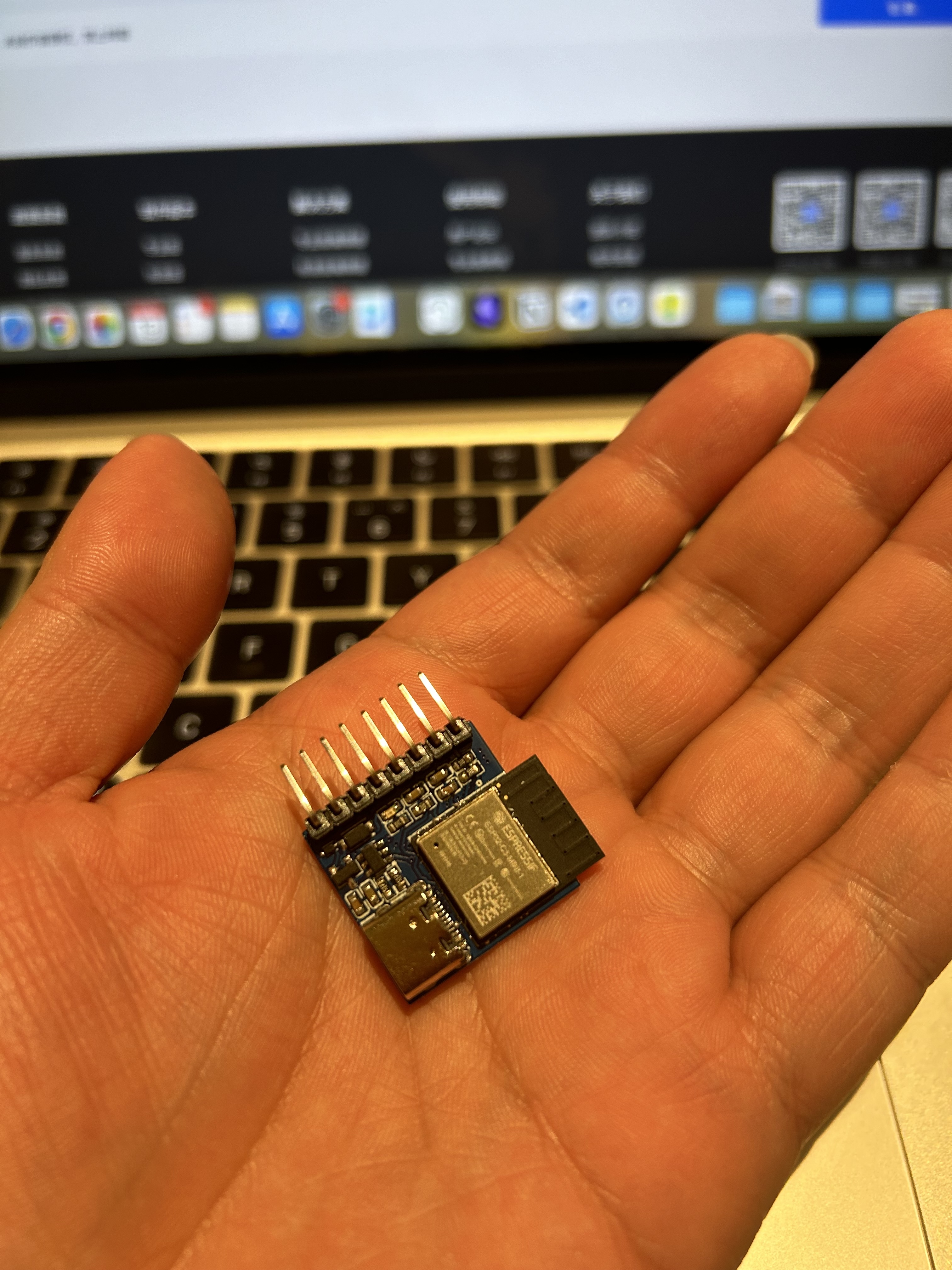
PS2 My previous designs were largely based on LCSC's designs. This development board was designed according to my own needs. If you find it helpful, please give it a thumbs up! Here's a picture
of the finished product
alongside the official LCSC development board (left: ESP32C3, right: ESP32C2, top: my ESP32C3)
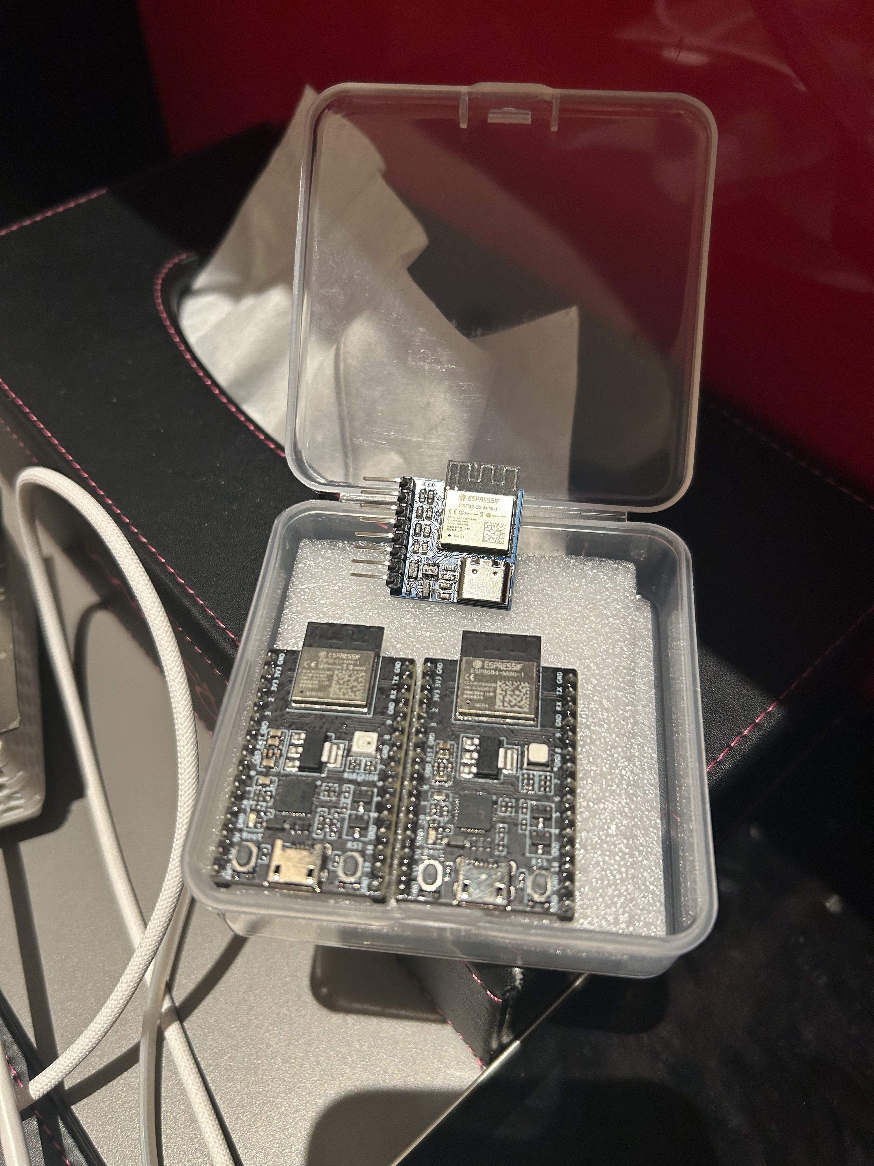
and a picture of my hand.

Cost estimate and purchase recommendations
: Main components are as follows:
Component Name
Reference Price
Purchase Channel
Link
PCB
/
LCSC
/
ESP32-C3-MINI-1-N4
12.2
Taobao (Shenzhen Youxin Electronics)
Search for
USB-TypeC (intercalation)
0.25
Taobao (Shenzhen Youxin Electronics)
Search for
USBBLC6-2SC6
0.42
Taobao (Shenzhen Youxin Electronics)
Search for
5V to 3.3V Linear Regulator LDO I bought
the 0.3
a bit too early. Everyone can search for SOT-223 packaged
capacitors, resistors, and other accessories on
Taobao
(Shenzhen Youxin Electronics). It's very cheap, right? You can get it for just over 13 yuan! Question: Does anyone have any other channels to recommend for the ESP32-C3-MINI? I think it's still a bit expensive. Hardware design/PCB design instructions are nothing special, simple and clear, right? Usage tutorials : My personal preferred methods are: ESPHome: Generally, you only need to flash it once, and then you can directly upload the firmware via OTA on the web page. Simple and easy to use. Tasmota: You can flash it by opening the web page. If the functions are not satisfactory, you can copy, modify, and compile. Actually, I haven't used Tasmota for a long time, but after researching it, I found that Tasmota can directly configure matter! (The ESP32C2 development board freezes after configuring matter, while the C3 is smoother and more reliable.) Open Source License: GPL 3.0 Project Name: Leize Intelligent_ESP32C3mini Development Board Copyright (C) 2024 Leize Intelligent This project is open source under the GPL 3.0 license, meaning you are free to use, modify, and distribute the source code of this project, but you must comply with the following conditions: When using, modifying, or distributing this project, you must clearly indicate the original author as "Leize Intelligent" and must not remove the original "Leize Intelligent" brand logo from the open source work. Use of this project is limited to the non-commercial domain. Commercial use requires additional authorization from the original author. You must also open source any modifications or derivative works based on this project under the GPL 3.0 license and retain the original author information. Please note that this project is provided "as is" without any express or implied warranties or conditions. To the maximum extent permitted by applicable law, Leize Intelligent will not be liable for any direct, indirect, incidental, special, punitive, or consequential loss or damage. For more information, please refer to the GPL 3.0 license document. Contact information: WeChat ID: rez-ti
PDF_Ultra-small ESP32C3mini development board, recommended for beginners (verified).zip
Altium_ultra-small ESP32C3mini development board, recommended for beginners (verified).zip
PADS_ultra-small ESP32C3mini development board, recommended for beginners (verified).zip
BOM_Ultra-small ESP32C3mini development board, recommended for beginners (verified).xlsx
91567
LED control board based on SY7203DBC
LED driver board using SY7203DBC chip
This is an LED driver board using the SY7203DBC chip. For portability, a 21700 lithium battery has been added. The charging IC is an Ingenic IP2315, and the battery protection IC is an IP3005A.
The brightness control section of the SY7203 uses a GP9101 as an external PWM signal source, powered by a TPS61022 which draws power from the battery and boosts it to 5V (a significant overkill, but this design was intended to verify the TPS61022). For a lower-cost replication, the TPS61022 can be replaced with other chips. The GP9101 has very low power consumption, so a 500mA DC-DC converter should be sufficient.
The board uses a 2-series, 10-parallel configuration. Custom boards are available for other requirements.
PDF_LED Control Board Based on SY7203DBC.zip
Altium_LED Control Board Based on SY7203DBC.zip
PADS_LED Control Board Based on SY7203DBC.zip
BOM_LED Control Board Based on SY7203DBC.xlsx
91568
eWeLink WiFi Light Switch (Single Channel) [Upgraded Version for Better Performance]
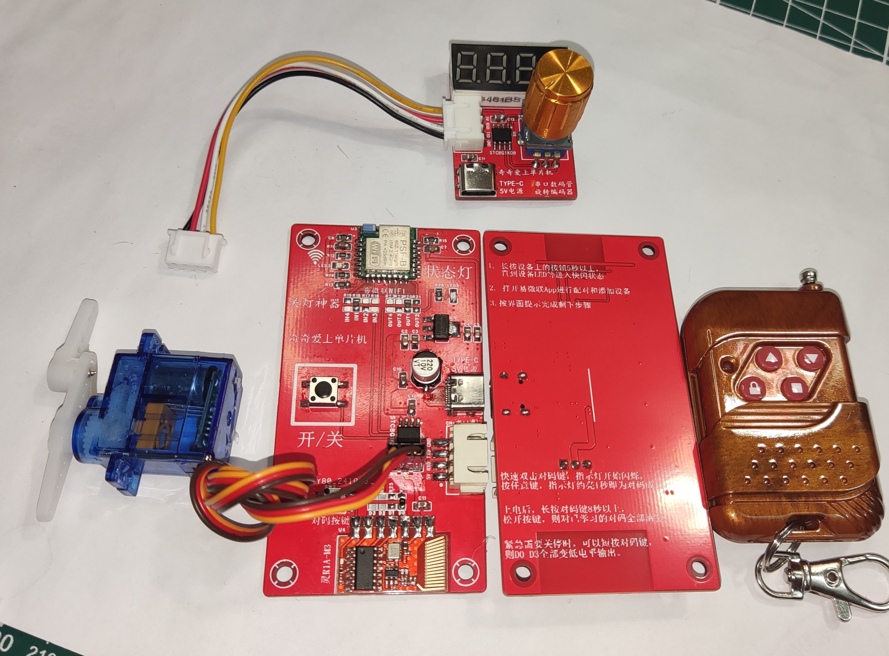
Based on feedback from numerous users, the dormitory light switch for college students has been fully upgraded. It features a clamp for a more stable grip on the 86-cell light box, added LED status lights and buttons, and an integrated design for faster and more sensitive response. It also boasts a timer function for turning lights on and off, remote control via mobile phone, and 433MHz wireless control within 70 meters.
Two PCB files are provided for different application scenarios. You can create your own PCB according to your needs.
The program can be downloaded directly (the program has been optimized as of November 20, 2024; the servo returns to center 1 second after movement to avoid damage caused by prolonged panel jamming – highly recommended!). This
is a must-have for university dormitory light switches. The schematic, source code, and PCB are open-source. Multiple people can remotely control a single switch outdoors, and it can also be connected to a Xiao Ai speaker for control.
I initially saw a similar product on Taobao and thought it was very creative, so I quietly noted it down. I wanted to buy one, but the finished product was expensive and couldn't connect to the network, so I decided to make one myself.
The simplest components are: an eMicroLink PSF-B04 module + an STC8G1K08 + an SG90 servo motor, forming a single-channel independent servo motor with angle data retention even after power loss.
The servo angle can be modified using a host computer serial port assistant or fine-tuned using a serial encoder control board. This is a single-channel design. The first step is to select channel 1, the second is to adjust the closing angle, and the third is to adjust the opening angle.
Refer to the video tutorial at https://oshwhub.com/liujianqi1688/dan-pian-ji-guan-deng-shen-qi-lan-ren-kai-guan.


There is also a separate control board, which is recommended!

//The source code and PCB for the above project are publicly available. Search for the username "奇奇爱上单片机" on the "LCSC Open Source Hardware Platform".
//Microcontroller model: STC8G1K08 //1. When burning the program, be sure to select built-in IRC=30MHz. //2. Change the IRC debugging mode to "Do not adjust, use the internal preset frequency". //2. Set the reset pin to the IO port. //3. Uncheck the option to erase the user EEPROM area when downloading the user program.
/*No technical support is provided; this is just for sharing out of passion. This is an open-source blogger's work; it is for use only and not for commercial purposes. For questions, please discuss in the comments section below. */ This solution was designed by: Qiqi (
TikTok): Mr. Qiqi (Most Adorable Qiqi in the Universe); Kuaishou ID: Qiqi Loves Microcontrollers; Bilibili: Qiqi Loves Microcontrollers; QQ: 1715755109 (For custom microcontroller programming and PCB design, please add me as a friend and indicate your purpose. Paid design services available; serious inquiries only). QQ Group: 499067314 (Welcome all microcontroller enthusiasts to join the group; group files and materials are available for free download).
STC8G1k08 microcontroller configuration before download. (bmp file)
eWeLink WiFi Light Switch Single Channel Version.zip
Lights-off gadget video demonstration.mp4
Demonstration video.mp4
Servo control switch demonstration video.mp4
The program has been optimized in 20241120. The servo now returns to center 1 second after each action, preventing damage from prolonged jamming of the control panel. Highly recommended. (zip file)
PDF_eWeLink WiFi Light Switch Single Channel [Third Generation Upgraded Version, Even Better].zip
Altium_EasyLink WiFi Light Switch Single Channel [Third Generation Upgraded Version for Better Performance].zip
PADS_eWeLink WiFi Light Switch Single Channel [Third Generation Upgraded Version for Better Performance].zip
91569
Air-flipping PPT
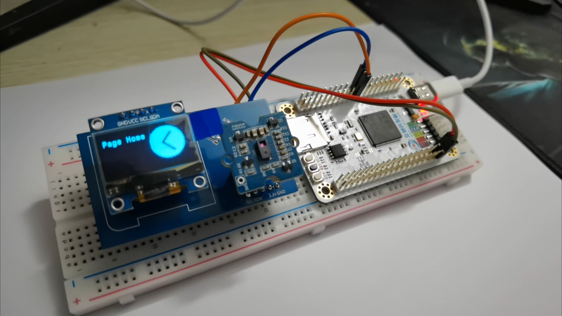
Using the STM32 F407's built-in USB peripheral and an external gesture recognition sensor, this enables air-gesture page turning in computer PPT presentations and web pages.
Video Link:
Bilibili Video -- Function Demonstration and Introduction (Demonstration video not yet produced)
Project Introduction
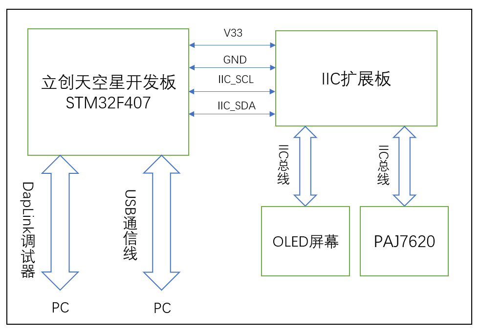
This project is a PPT electronic application based on the LCSC SkyStar development board, featuring air-based page turning. The main circuit modules used are the LCSC SkyStar development board, an external gesture recognition sensor circuit, and an OLED screen. The OLED screen displays the gesture type/page-turning action type.
Project Function
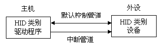
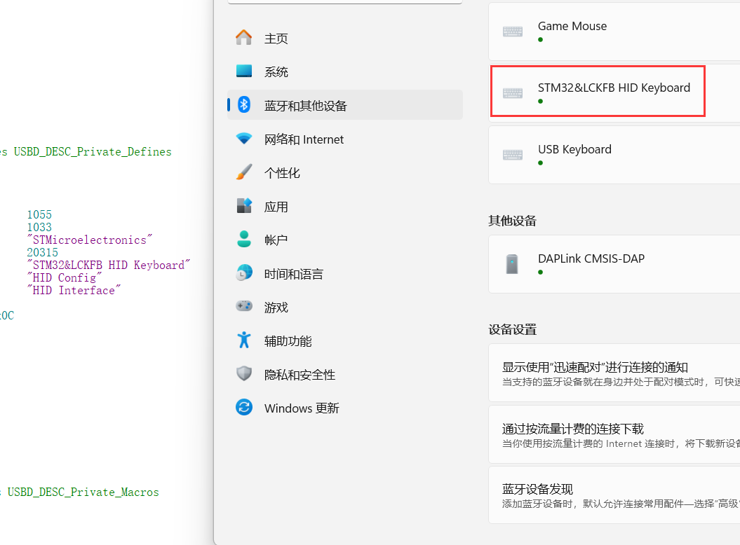
This design uses the LCSC SkyStar development board as the main control board. After the main control board's MCU collects data from the gesture recognition sensor, it sends corresponding HID commands to the PC based on the parsed gesture type to complete the PPT page turning.
1. Using JLCSC EDA, an expansion circuit board design was completed. A new gesture recognition module circuit was redesigned based on the reference application circuit of the gesture sensor IC. The module's communication interface is IIC, which also exposes an SPI communication interface. Therefore, the expansion board also exposes SPI communication pins, allowing the PAJ7620 to use SPI communication later. PCB version 1 is an expansion board design, and PCB version 2 is an independent design for the gesture recognition module
. 2. To complete the PPT page turning on the PC, the STM32 F407's built-in USB peripheral needs to communicate with the PC via a USB data cable. During the communication process, the corresponding USB protocol analysis tool can be used to parse the communication data. Correct test data parsing indicates that the USB communication is normal.
Project parameters:
This design uses the PAJ7620 gesture recognition sensor, which has accurate gesture recognition capabilities;
This design uses the STM3F407 series main control MCU, which has a USB communication interface and also has high-speed bus communication and high-speed data processing capabilities;
This design uses a 0.96-inch OLED module, and the screen driver IC is the SSD1306, a common single-chip microcontroller screen module with advantages such as simple driving and small image array data volume.
Principle analysis (hardware description):
PAJ7620 IC internal structure diagram.
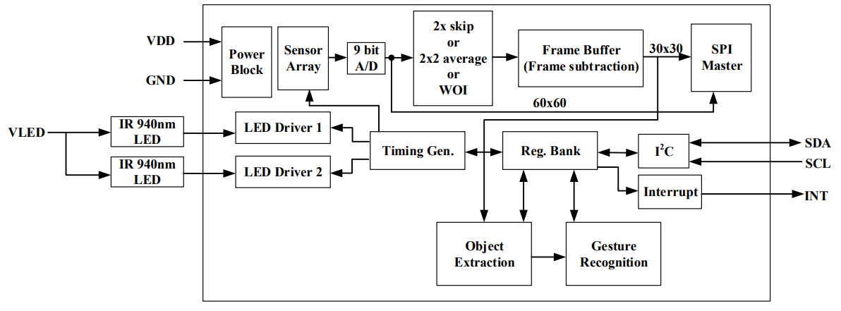
Sensor introduction:
PAJ7620U2 The chip is an optical array sensor from PixArt, integrating an LED with a built-in light source and ambient light suppression filter, a lens, and a gesture recognition sensor. It can operate in dark or low-light environments and features gesture recognition and object proximity detection supporting nine gestures. The gesture recognition module uses an III2C interface and can be programmed and controlled using corresponding library functions. The signals returned by the gesture recognition module can be used as control signals for the robot, enabling robot control. The built-in recognition algorithm is quite intelligent, freeing hands from cumbersome button presses. The gesture recognition sensor can be used in non-contact control scenarios such as non-contact mice, smart homes, automotive click device control, and robot interaction. The types of
recognizable gestures are shown in the following figure:

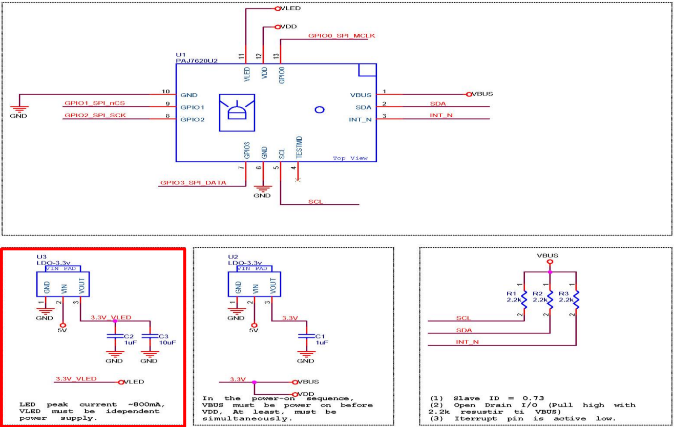
Example Figure 1 – PAJ7620 Reference Design Circuit:
The software program adopts both hardware IIC and software IIC driving methods. Software IIC allows flexible switching of drive pins, but the screen refresh rate is not as fast as hardware IIC. The above two driving methods can be switched with a single key using a macro definition flag in the main.h header file.
Hardware IIC connection pins:
VCC<->V33
GND<->GND
SCL<->PB8
SDA<->PB7
Software IIC connection pins:
VCC<->V33
GND<->GND
SCL<->PD10
SDA<->PD12
Devices and programming tools used:
STM32CubeMX version 6.12.0,
MDK Keil version 5.38.0,
LCSC Skystar development board main controller model STM32F407VGT6,
gesture recognition module IC model PAJ7620,
OLED screen IC model SSD1306,
DapLink debugger version daplink_V1.0
Software code
example code:
enum keycode{ //keyboard function code enumeration
pageUp=0x4B, //page up
pageDown=0x4E, //page down
pageHome=0x4A, //jump to home page
pageEnd=0x4D //jump to end page
};
void keyboard_code(uint8_t kc){ // Keyboard HID report descriptor
uint8_t HID_Buffer[8] = {0}; // Keyboard send data buffer size is 8, mouse is 4
uint8_t HID_Buffer_clean[8] = {0};
HID_Buffer[0] = 0x00;
HID_Buffer[1] = 0x00;
HID_Buffer[2] = kc;
USBD_HID_SendReport(&hUsbDeviceFS, HID_Buffer, sizeof(HID_Buffer));
HAL_Delay(200);
USBD_HID_SendReport(&hUsbDeviceFS, HID_Buffer_clean, sizeof(HID_Buffer_clean));
HAL_Delay(200);
paj_update_flag=0;
}
if(Gesture_Data !=0)
{
paj_update_flag=1;
switch (Gesture_Data)
{
case PAJ_UP:
printf("Up
"); //Note that the USB is connected to the PC
//k_code=pageUp;
keyboard_code(0x4B);
ssd1306_SetCursor(2, 8);
screenClear();
drawPicture(image_c,0);
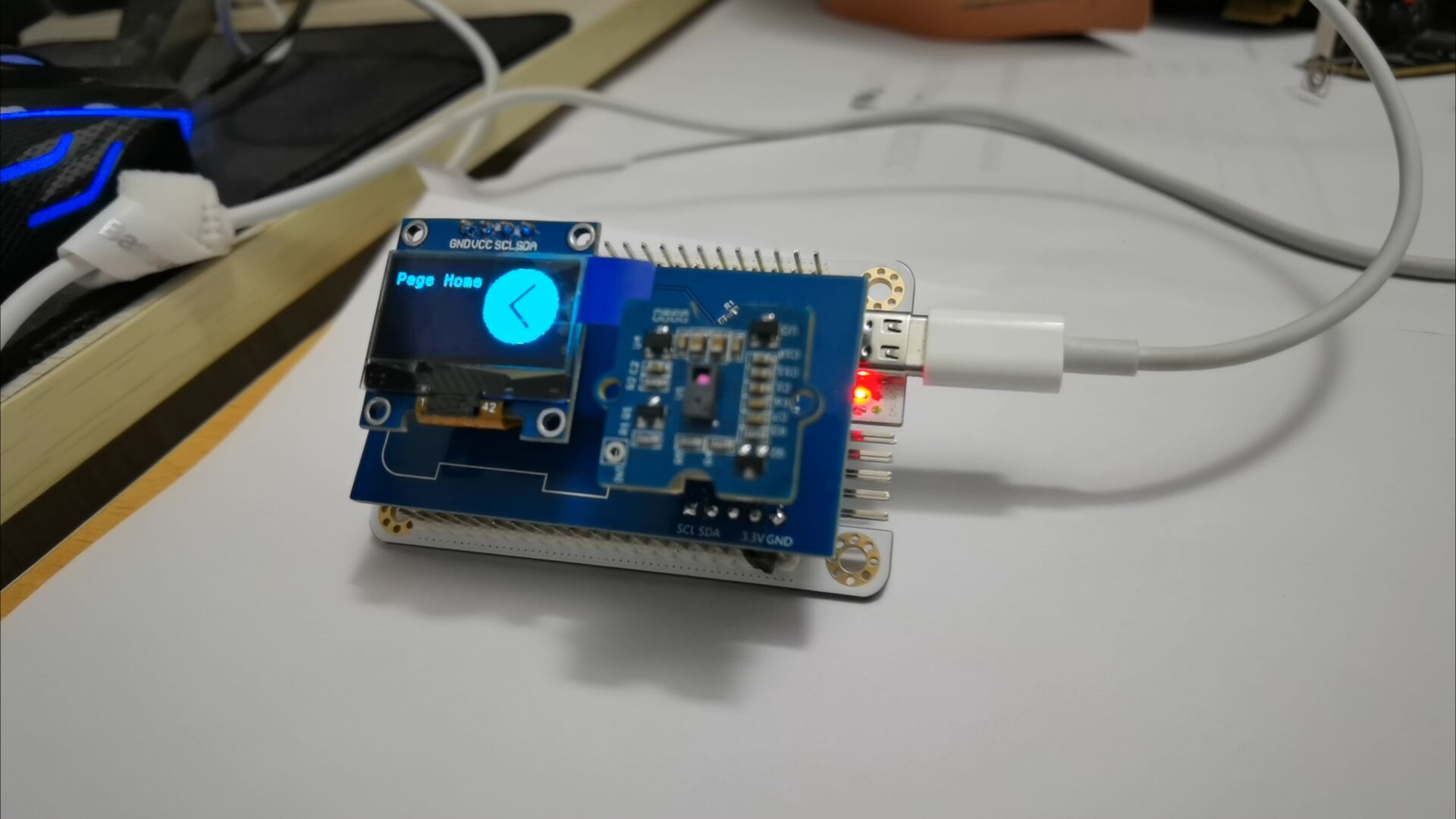
ssd1306_WriteString("Page Up", Font_7x10, White);
break;
case PAJ_DOWN:
printf("Down
");
//k_code=pageDown;
keyboard_code(0x4E);
ssd1306_SetCursor(2, 8);
screenClear();
drawPicture(image_d,0);
ssd1306_WriteString("Page Down", Font_7x10, White);
break;
case PAJ_LEFT:
printf("Left
");
k_code=pageHome;
keyboard_code(0x4A);
ssd1306_SetCursor(2, 8);
screenClear();
drawPicture(image_aaa,0);
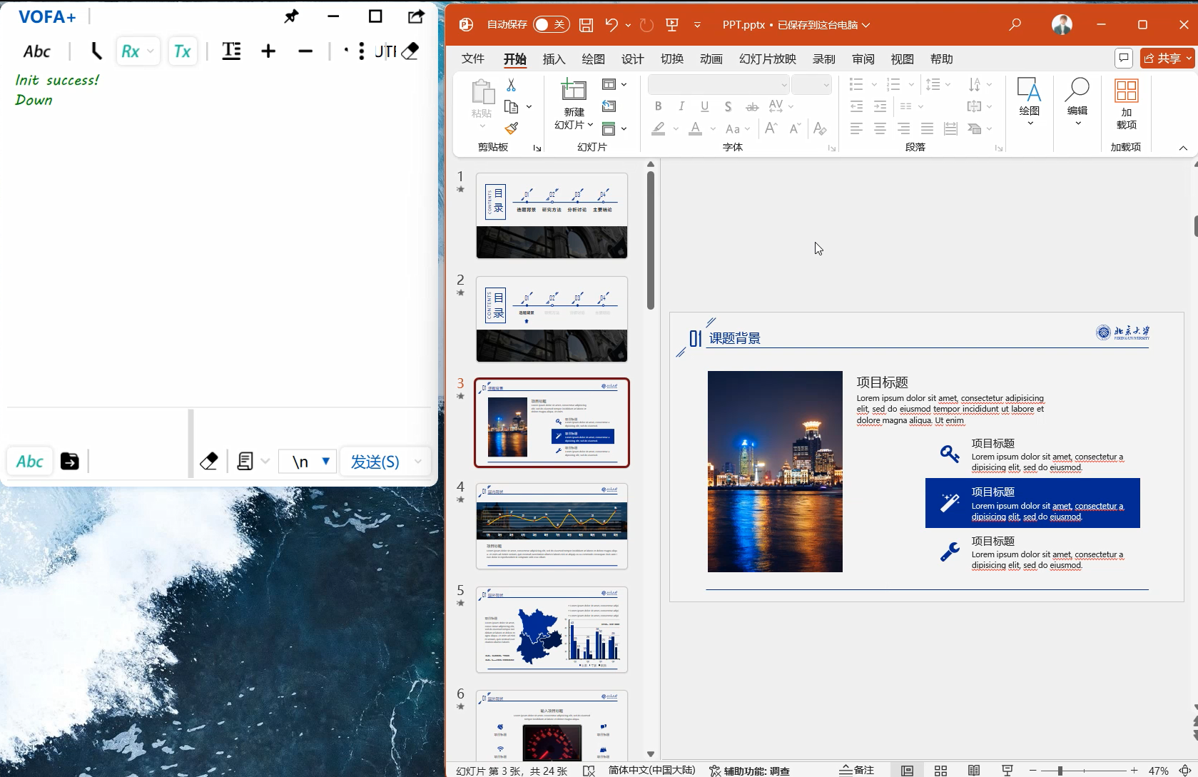
ssd1306_WriteString("Page Home", This project has been open-sourced and uploaded to Gitee, link below (https://gitee.com/quansirx/gesture-for-page-flip).
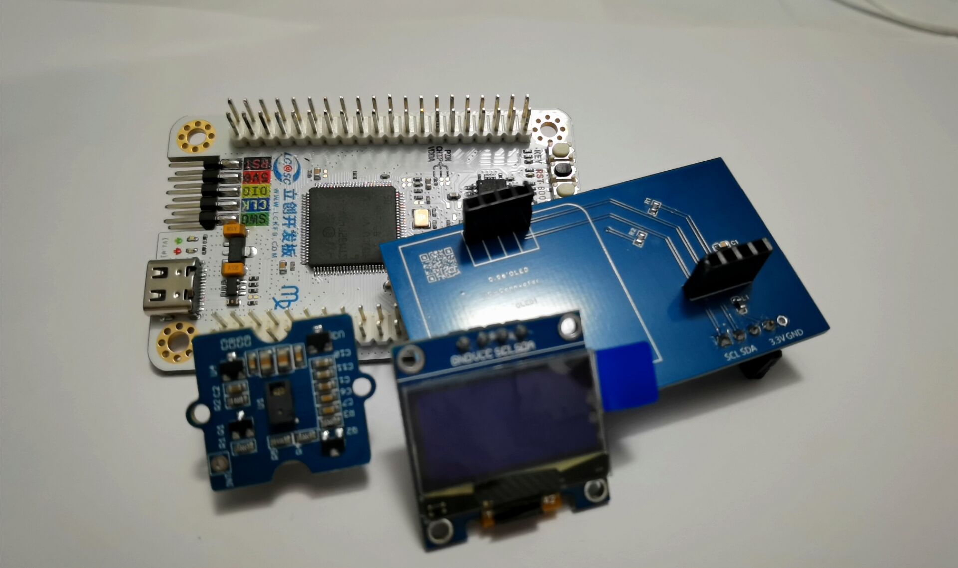
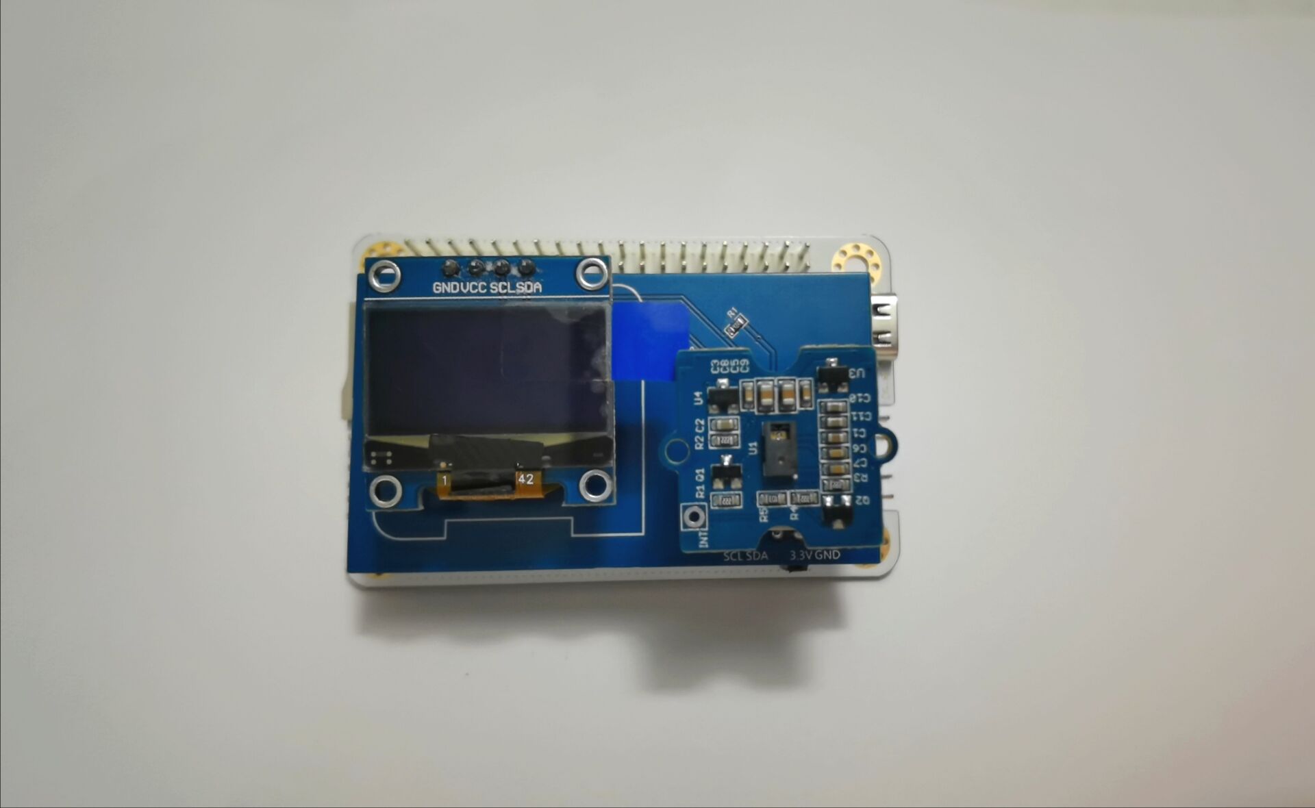
Introduction to USB HID Protocol: HID (Human Interface Device) is a common device type in USB devices, directly interacting with humans, such as keyboards , mice, and joysticks. HID devices are relatively inexpensive compared to other USB devices. Furthermore, HID devices do not necessarily require human-computer interaction; any device conforming to the HID category specification is an HID device. Windows operating systems were the first to support HID devices. Windows 98 and later versions have built-in drivers for HID devices, which applications can directly use to communicate with the devices. When designing a USB computer peripheral, if an HID type device meets the requirements, it can be designed as an HID type device. This avoids the complex writing of USB drivers and directly utilizes Windows operating system's support for standard HID type USB devices. HID devices are characterized by storing exchanged data in a structure called a report, and the device firmware must support the HID report format. The host transmits and receives data by controlling and interrupting transmissions and requesting reports. The report format is very flexible. Each transaction can carry small or medium amounts of data. Low-speed devices have a maximum of 8 bytes per transaction, and a report can use multiple transactions. Full-speed devices have a maximum of 64 bytes per transaction , and high-speed devices have a maximum of 1024 bytes per transaction. In addition to transmitting data to the host, an HID device also receives data from the host. Any device that conforms to the HID category specification can be an HID device. Besides the HID interface, the device may also include other USB interfaces. For example, a video display device might use an HID interface for software control of brightness and contrast, while using a traditional video interface to transmit the data to be displayed. A USB speaker might use real-time transmission to play audio while using an HID interface to control volume, bass, etc. Important Notes: The following are key points or common mistakes to pay attention to during design and production. When driving the USB HID to establish communication with the computer, pay attention to the HID report descriptor settings; during circuit board design, pay attention to the pull-up IIC bus, because the IIC device output is open-drain; when driving the OLED screen, remember to clear the screen first, and then draw the text and image content. Assembly Process Physical Framework Diagram : Figure 1: Physical Assembly Diagram; Figure 2: Running Effect Diagram (Software IIC) ; Figure 3: Running Effect Diagram (Hardware IIC) ; Figure 4: Running Effect Diagram; Figure 5: Running Effect Diagram. Finally, to summarize briefly, considering that the PAJ7620 has an SPI interface, it is feasible to redesign the PAJ7620 circuit using JLCPCB EDA and bring out the SPI communication interface. Due to a shortage of PAJ7620 components, only the expansion circuit board was prototyped. The VCC and GND pins on the expansion board did not align with the development board's pin headers. Therefore, a "flying wire" method was used: a small copper-clad area was cut out of the expansion board, and a row of female GND pins was soldered onto it. Finally, the female pins were connected to the development board's GND, resolving the misalignment issue between the expansion board and the development board's slots. The drawback was that the large copper-clad area on GND made it difficult to apply solder to the scraped copper area. Eventually, the solder adhered after continuous heating of the scraped copper area with a soldering iron. The circuit design is open-source on the JLCPCB open-source hardware platform, and the source code has been uploaded to the Gitee repository. Interested electronics enthusiasts can check it out.

Gesture-based page turning - demonstration video.mp4
STM32F407VGT6_NORTOS_USB_IIC.zip
Gesture-based page turning - demonstration video.mp4
Gesture-based page turning - demonstration video.mp4
PDF_Air Flip PPT.zip
Altium_Air Flip PPT.zip
PADS_Air Flip PPT.zip
BOM_Air Flip PPT.xlsx
91570
NE555 Multi-Circuit Experiment Board
Experimental board for NE555 three-element circuit
This project introduces
experimental boards for NE555 bistable, monostable, and astable circuits, allowing users to learn the basic principles of the NE555.
The project's function
involves observing the blinking of an LED and the generation of square and triangular waves by changing capacitors and adjusting resistance values.
Principle Analysis (Hardware Description)
: Bistable Circuit:

After pulling up pin 2 and pin 6, two switches are used to control the potentials of pins 2 and 6 respectively, achieving two stable states: on and off.
Monostable Circuit:
Pins 6 and 7 are shorted, a capacitor is connected to ground, and an adjustable resistor is connected to the power supply for current limiting. The rest is the same as the bistable circuit. After pin 2 is triggered, pin 7 no longer discharges to ground, allowing the power supply to slowly charge the capacitor, gradually raising the potential of pin 6. When the voltage reaches 2/3 of the power supply voltage, pin 6 is triggered, the LED turns off, pin 7 discharges to ground again, and pin 6 returns to a low potential. The LED's illumination time can be adjusted by changing the resistor and capacitor values.
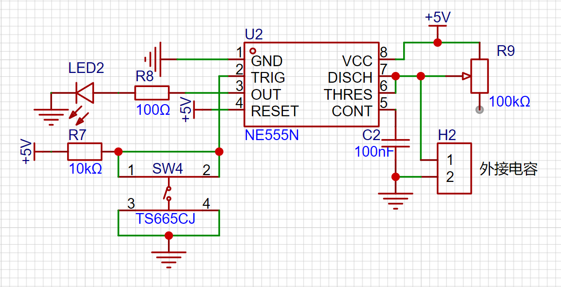
Astable Circuit:
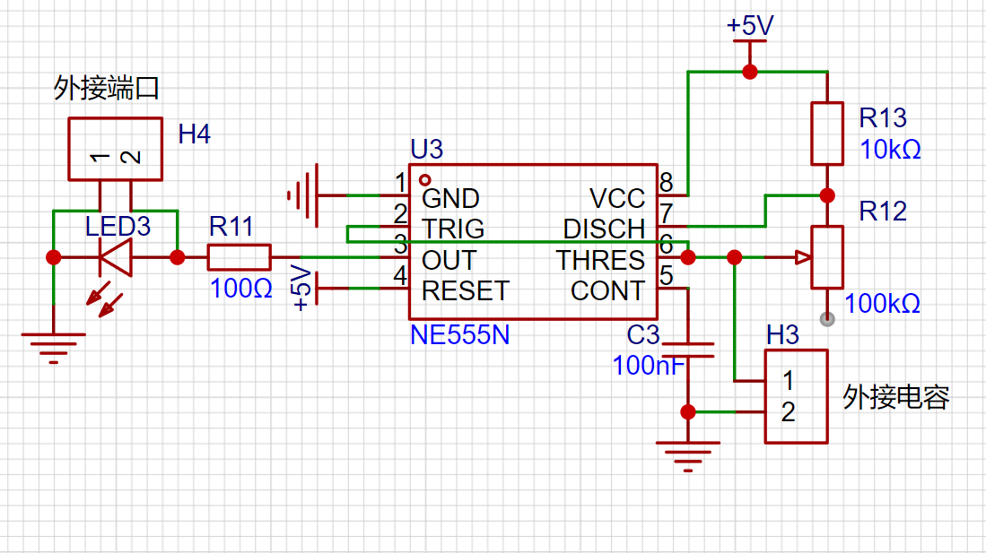
Pins 2 and 6 are shorted, a capacitor is connected to ground, and a resistor is connected to the power supply. After power is turned on, the capacitor's initial voltage is 0, pin 2 has a low potential, and the LED is on. As the capacitor voltage gradually rises to 2/3 of the power supply voltage, pin 6 is triggered, the LED turns off, and pin 7 discharges to ground. When the capacitor voltage drops to 1/3 of the power supply voltage, pin 2 is triggered, the LED lights up, and the cycle repeats.
By using a smaller capacitor value, a square wave is generated at pin 3, and a triangular wave is generated at pins 2/6, as shown in the diagram: [Image of
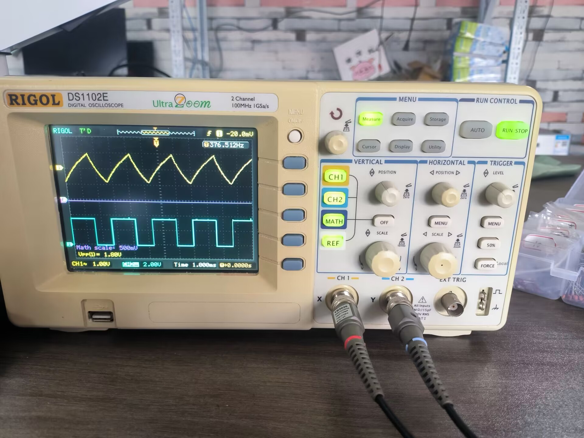
actual device demonstration]
Bistability.mp4
Monostable.mp4
Unstable state.mp4
PDF_NE555 Multi-Circuit Experiment Board.zip
Altium_NE555 Multi-Circuit Experiment Board.zip
PADS_NE555 Multi-Circuit Experiment Board.zip
BOM_NE555 Multi-Circuit Experiment Board.xlsx
91571
Skystar GD32 Smart Car Expansion Board
This is a smart car expansion board made using the LCSC Skystar GD32F407VET6 development board - Youth Edition.
Video Link:
Bilibili Video -- Function Demonstration and Introduction
Project Overview
This project is an expansion board for a smart car based on the LCSC Skystar GD32F407VET6 development board - Youth Edition.
It uses two TB6612 chips
and PCA9685-16-channel servo motors for driving, with 6 channels actually brought out.
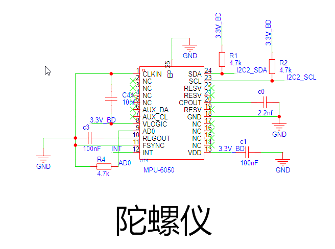
The gyroscope uses an MPU6050 .
The screen is a 1.54-inch 240x240 high-definition IPS LCD display with integrated backlight.
Project Functions
Drive 4 motors.
Drive 6 servos.
The MPU6050 gyroscope
can be connected to a 3.7V lithium battery, providing charging functionality.
1.54-inch 240x240 screen displays
Project Parameters
This design uses the MPU6050, integrating a 6-axis Motion Tracking device. It integrates a 3-axis MEMS gyroscope, a 3-axis MEMS accelerometer, and a scalable Digital Motion Processor (DMP).
This design uses the TB6612 motor driver, a Toshiba Semiconductor IC for driving motors. One TB6612FNG can drive two motors, each with two logic input pins, one output pin, and one PWM pin. The motor's operating state can be controlled by applying different levels to the two logic input pins, and the motor speed can be adjusted via the PWM input pin.
The PCA9685 is selected; it is a 16-channel PWM servo motor driver based on the I2C bus. Internally, it integrates 16 PCA6124 PCA bus servo drivers, providing independent PWM control signals for 16 servo motors. Each channel can independently set the PWM width, thereby precisely controlling the servo motor's rotation angle.
The
project consists of the following parts: charging section, motor drive section, servo drive section, and gyroscope section.
The charging circuit uses an IP5306 and includes a switch.

The TB6612 consists of two
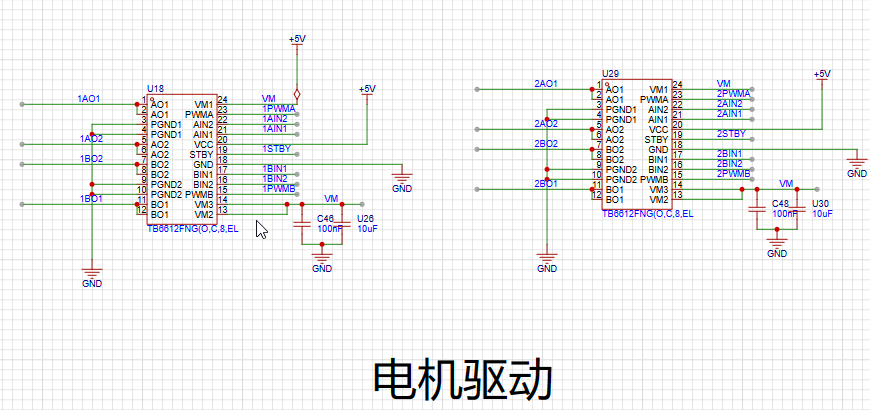
servo motor drivers as shown below. The actual value uses a 6-channel PWM output

gyroscope circuit. AD0 grounding
software code
is available in the attached zip package.
Notes:
No
assembly process
provided. Actual
product image omitted.


Smart Car Expansion Board.zip
202410042131~1.mp4
Car video.mp4
PDF_SkyStar GD32 Smart Car Expansion Board.zip
Altium_SkyStar GD32 Smart Car Expansion Board.zip
PADS_SkyStar GD32 Smart Car Expansion Board.zip
BOM_SkyStar GD32 Smart Car Expansion Board.xlsx
91572
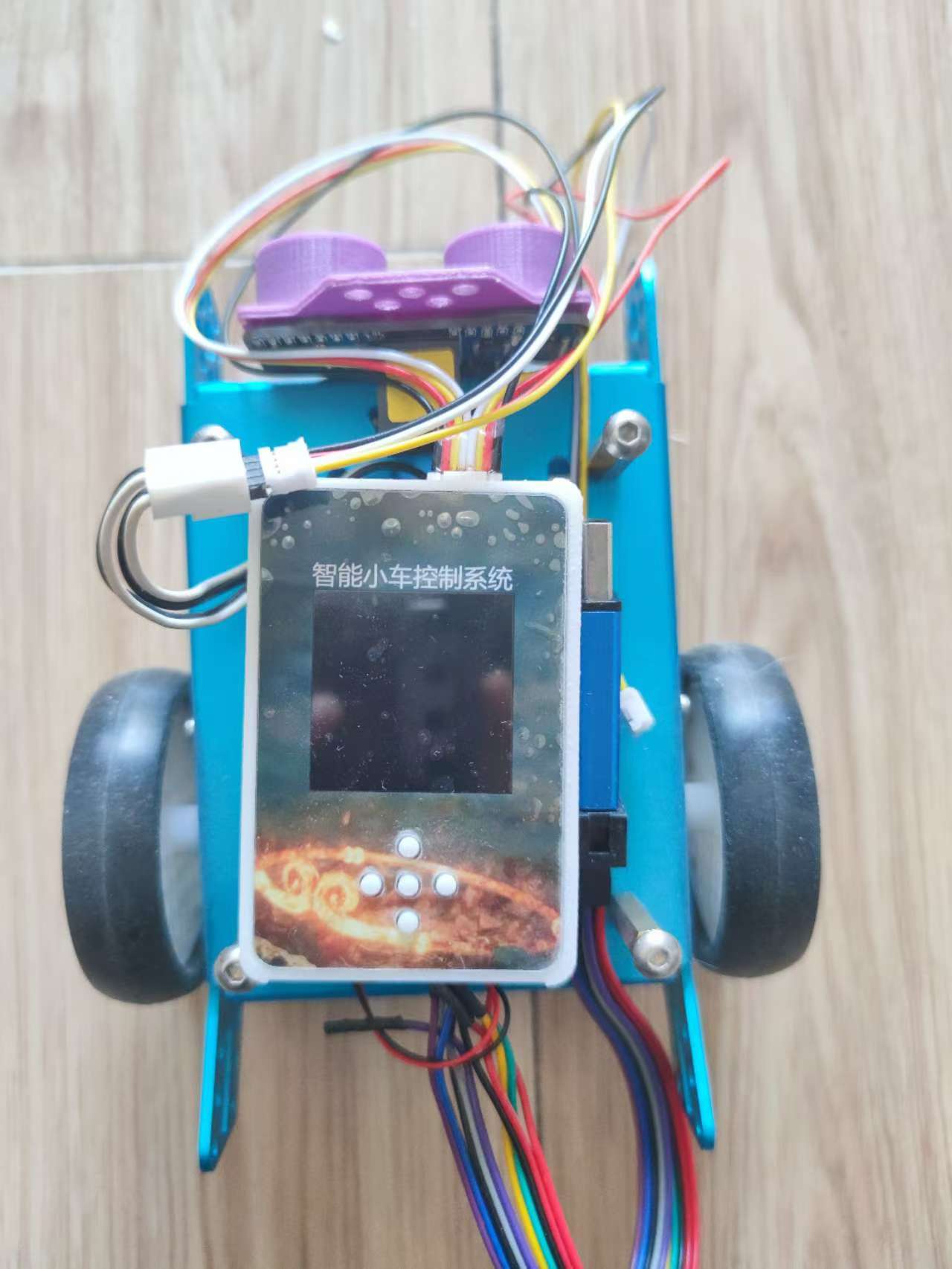
LCSC Skystar Semiconductor Refrigerator
LCSC SkyStar Semiconductor Refrigerator Extended Version
Project Introduction:
A LCSC SkyStar semiconductor refrigerator expansion board, supporting 40-pin development boards such as STM32F103 core board and GD32E230 core board.
Project Function:
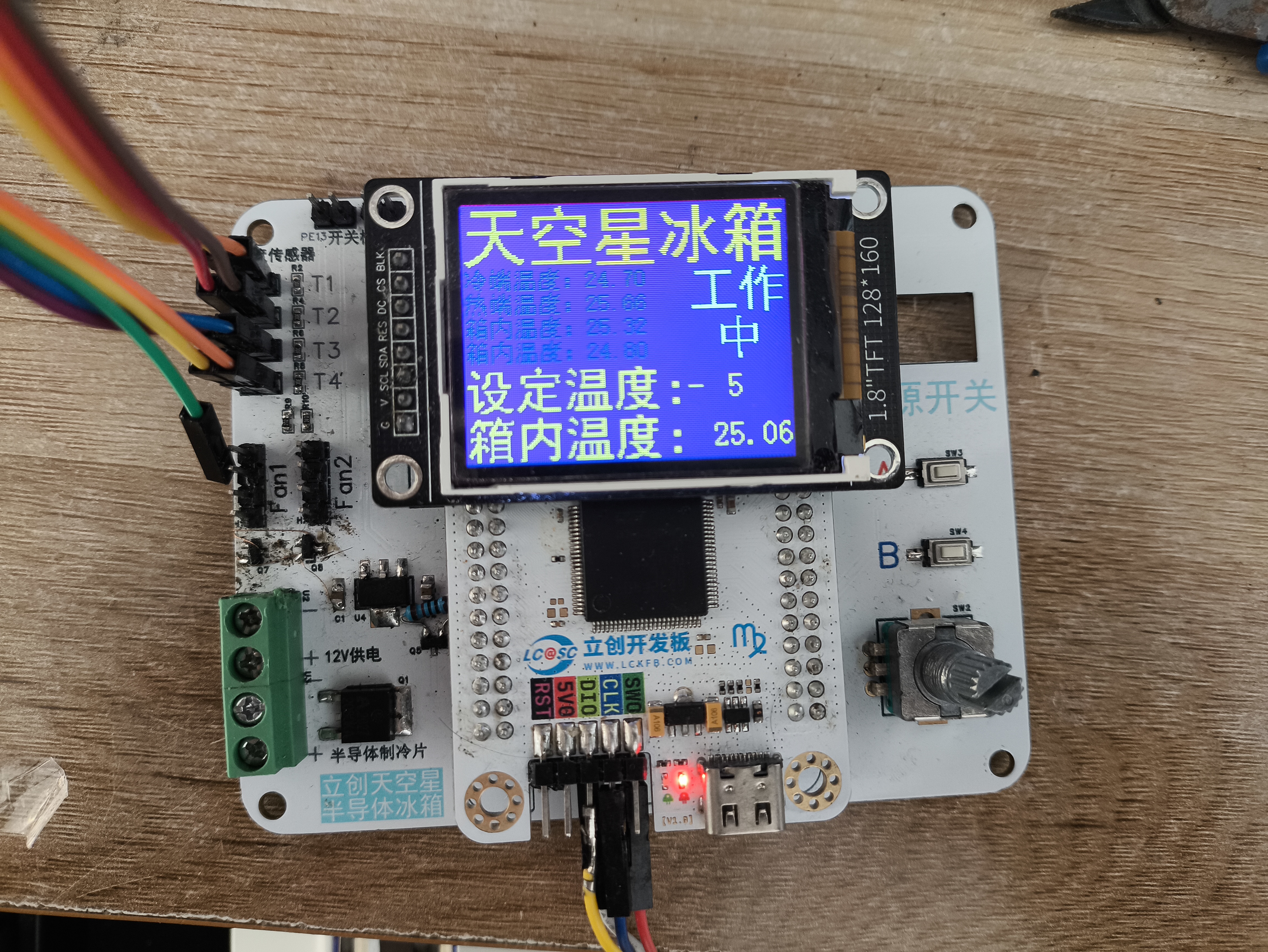
A semiconductor refrigerator control board based on GD32F407VET6.
Project Parameters:
GD32F407VET6
12705 semiconductor cooling chip ,
CPU cooling fan
, 10k thermistor (measuring cold junction, hot junction, and internal temperature),
3V lighting.
Precautions:
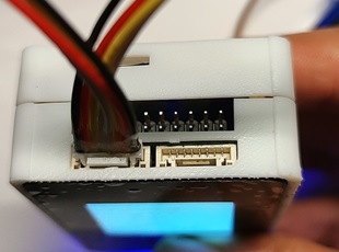
Ensure the TFT screen interface definition is consistent.
The display interface uses an 8-pin extended female connector.
Assembly Process:
Uses M3x8+6 hex studs, M3x5 machine screws, and M3 nuts.
Actual Product Image.

Program code.rar
main.c
PDF_LCSC SkyStar Semiconductor Refrigerator.zip
Altium_LCSC SkyStar Semiconductor Refrigerator.zip
PADS_LCSC Sky Star Semiconductor Refrigerator.zip
BOM_LCSC Skystar Semiconductor Refrigerator.xlsx
91574
CH32V307-based quadcopter drone flight control system
The CH32V307 is used as the main controller, the IMU is an Mpu6050, the magnetometer is a QMC7983, and a barometer is a BMP280. It features one-click download and debugging via USB-C and only supports the CRSF protocol.
Hardware Notes:
H3 is the ELRS receiver serial port. Receiver reference: https://oshwhub.com/vinvaa/elrs2-4g. It has a 5V power output. Other interfaces are for the expansion of
the onboard magnetometer QMC7983. However, due to a design error, it was not cascaded to the MPU6050 but instead connected to the same I2C bus as the MPU. Additional programming is required to resolve this, so it is not used, but it can be used for expansion. After modification, it can be used for filtering and inertial navigation. The onboard
TF card was not tested.
The onboard barometer BMP280 was tested, but its accuracy is poor.
The remote controller and receiver use a radio protocol; I used the ELRS radio protocol. The receiver and flight controller can only use the CRSF serial protocol. When designing or purchasing a receiver, please note
the following: Frame: MARK4, 7-inch, Motors: 1300kV, Three-bladed propeller,
Flight controller USB- Type-C supports one-click download. This Type-C port integrates serial port, download, and debugging.
H1 is an optical flow meter interface, supporting the Microspace MTF-01 and MTF-02 optical flow meters (note the wiring sequence). However, due to the lack of a magnetometer for data fusion, the integration effect is poor, and the coordinate calculation is inaccurate. Furthermore, the program only reads data and calculates coordinates; there is no program for controlling the fixed point.
After power-on, the firmware needs to be programmed into the CH549G chip using WCHISPTool_Studio before Type-C can be used for debugging the flight controller and serial printing. The firmware is located in the attached WCHLINK_V2.10.bin. Software Notes:
Use Mount River. The IDE manages the project and compilation
, while FreeRTOS manages the processes. To modify this, please go to User/RTOS_apps/.
Example code can be found at https://github.com/YifeiNie/CH32_FPV.git.
The aircraft is fully flyable. If problems occur during replication, it's definitely due to incorrect parameter settings or wiring issues. If the problem persists or a bug is confirmed, please contact @nieyf.
My hardware and software design capabilities are limited, and flight performance cannot be guaranteed. The PID parameters need further tuning.
Simply connect to the computer via USB and power on. You can view the flight control information through a serial port assistant. If it's garbled, please check if the baud rate is set to 230200.
The Print_status_task() function in the User/RTOS_apps/Print_status.c file is used to print various information. You can see different types of information by uncommenting and modifying the source code.
***Due to unknown reasons, possibly a software bug or a chip design issue, the PWM output occasionally experiences small, very short-duration jumps. For custom-made brushless ESCs using open-source ESC firmware (such as AM32), there is a chance this will be identified as a fault and the ESC will restart, causing one of the motors to suddenly stop during flight, resulting in serious consequences (crash/burnt MOSFETs or driver). The solution is to modify the ESC firmware to increase the number of fault detections. If more than three faults occur within a certain period, it is considered a genuine fault, and the problem will be solved. (Based on testing, various commercial ESCs can be used without faults.) Other precautions:
The example code is for reference only. Safety must be taken seriously when debugging drones! The project members are not responsible for any safety issues or property damage.
This project applies to various commercial brushless ESCs, but you must pay attention to the wiring sequence! Wiring sequence! Wiring sequence!
Due to my limited design capabilities, many wiring sequences are not direct-plug and are not foolproof. You must pay close attention, especially to how the output signals of the four motors of the quadcopter are connected and correspond. You must confirm clearly!
You must confirm the positive and negative terminals of the ESC power supply on the distributor board, as two of them are reversed!
You must confirm the function of each channel on the remote controller before test flight and make appropriate modifications.
Video 1.mp4
Image 1.png
WCHLINK_V2.10.bin
PDF_CH32V307-based Quadcopter Drone Flight Controller (with Flight Controller Firmware).zip
Altium_CH32V307-based Quadcopter Drone Flight Controller (with Flight Controller Firmware).zip
PADS_CH32V307-based Quadcopter Drone Flight Controller (with Flight Controller Firmware).zip
BOM_CH32V307-based Quadcopter Drone Flight Controller (with Flight Controller Firmware).xlsx
91575
electronic


 京公网安备 11010802033920号

 B32328A4256J033


