Disclaimer:
This open-source project is intended for professionals in the RF industry or users with basic RF knowledge, for academic exchange.
This project is shared free of charge for academic exchange purposes only and is prohibited from being used for illegal or commercial purposes. Users without RF background and related RF instruments are not advised to replicate this project, as unprofessional operation may lead to potential dangers. Replicating, or using, or referencing this project in any other form, constitutes acceptance of this disclaimer and full understanding of its contents. All dangers and consequences arising from replicating, or using, or referencing this project in any other form are the sole responsibility of the user and are not the responsibility of the project author.
I. Origin:
I accidentally discovered a neat-looking power amplifier tube, model BLM10D2327-60ABG. Its small size, high power, and attractive appearance appealed to me. So I made a board to play around with it.
II. Chip Information:
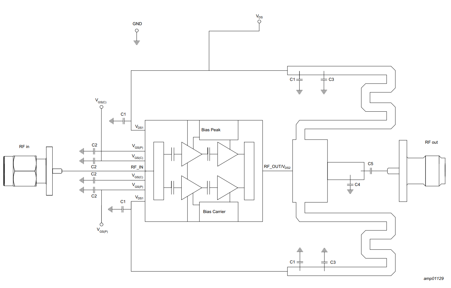
1. Chip Block Diagram:
As shown in the block diagram, this is a commonly used power amplifier structure in base station power amplifiers. However, this transistor integrates matching, power splitting, combining, and other components, making it more convenient to use and smaller in size. This is advantageous in applications where size is critical, such as PRRUs (Pre-Release Units). The specific principles will not be elaborated upon here; this open-source project is intended for users with some basic RF knowledge.

According to the manual,
this power amplifier transistor operates in the 2.4GHz band. With good heat dissipation, the gain is approximately 28dB, and it can output a maximum CW pulse power of +48dBm, which is 63W. The efficiency is approximately 40% or higher when the output power is +40dBm.

III. Electrical Design:
1. Power Supply Voltage Selection:
According to the manual, a 28V DC power supply is recommended.
2. BIAS Circuit Design:
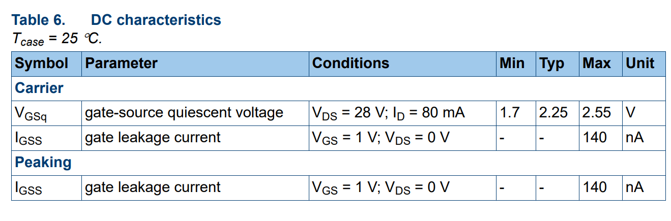
First, refer to the manual to determine the VGS voltage range.
As shown in the table below, the allowable voltage range of VGS is -6~+9V.

Continuing to read the manual, it can be seen that the required bias voltage during normal operation is approximately within 3V.
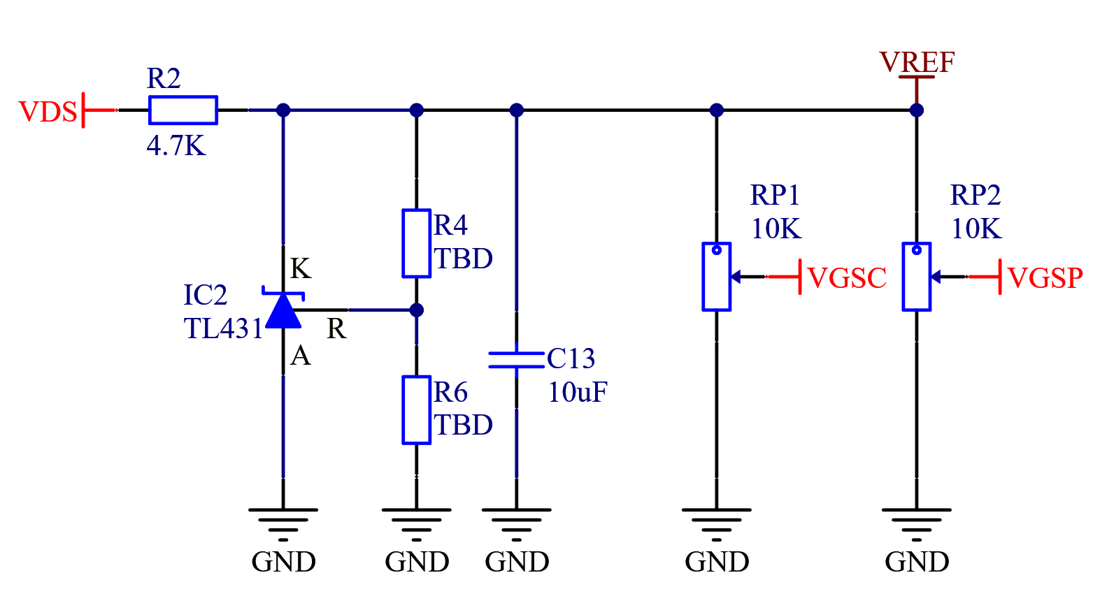
Since the bias has very low current requirements, we use the TL431 voltage reference chip to regulate the 28V power input to a stable VERF.
1.1 TL431 Principle:

The TL431 can be considered equivalent to a Zener diode. Its basic connection method is shown in the figure below. Figure a can be used as a 2.5V reference source, and Figure b can be used as an adjustable reference source. The relationship between resistors R2 and R3 and the output voltage is UO = 2.5(1+R2/R3)VO.

The VREF obtained from the TL431 is used as a voltage divider to provide biases for Peak and Carr respectively.
IV. Matching Circuit Design:
Since this transistor lacks an ADS model and S-Parameters, only the load impedance is provided in the datasheet. The datasheet also provides a matching reference design for the required frequency band, so we simply use the reference design to verify its functionality.
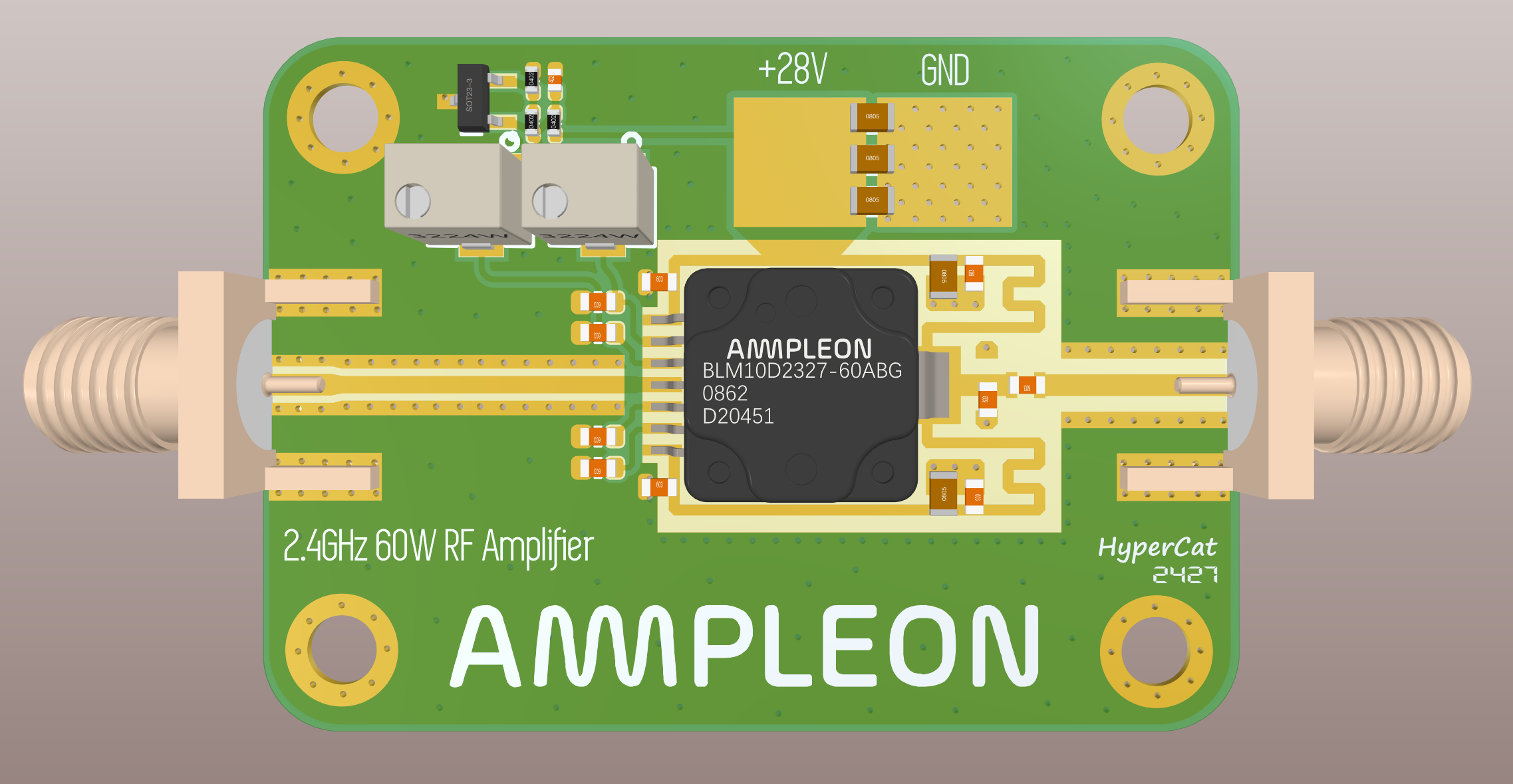
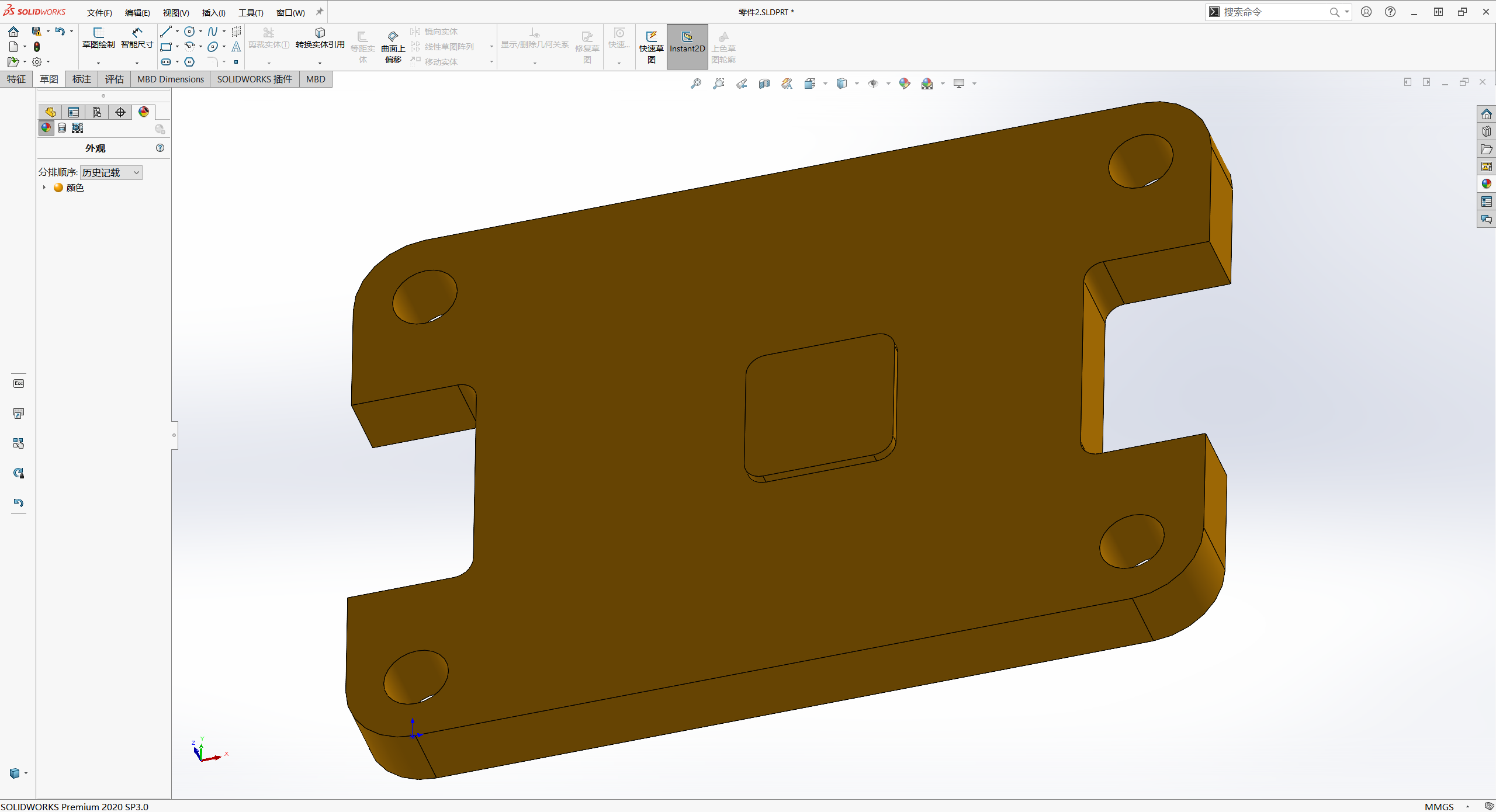
V. PCB Design: See LCSC EDA .
This image is a 3D rendering.
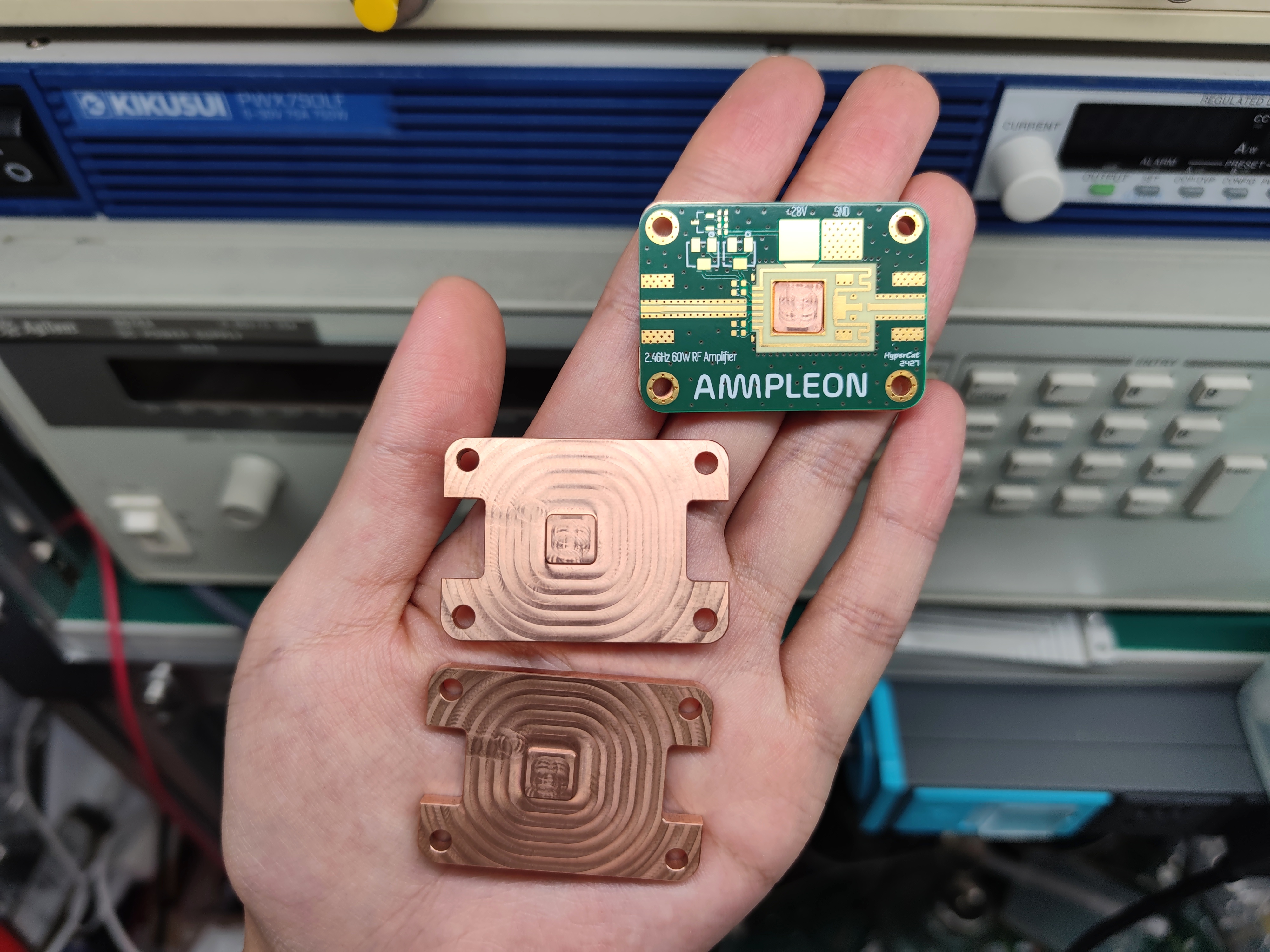
VI. Heat Dissipation Design:
Due to the significant heat generated by the RF power amplifier, a good heat dissipation design is necessary; otherwise, it will overheat and burn out. This transistor has no mounting lugs, so it needs to be soldered to a heatsink, which also serves as grounding and heat dissipation material.
The manual also recommends soldering directly to the heatsink material.

Therefore, we need to design a heatsink base for soldering, so the material must be copper, not aluminum.
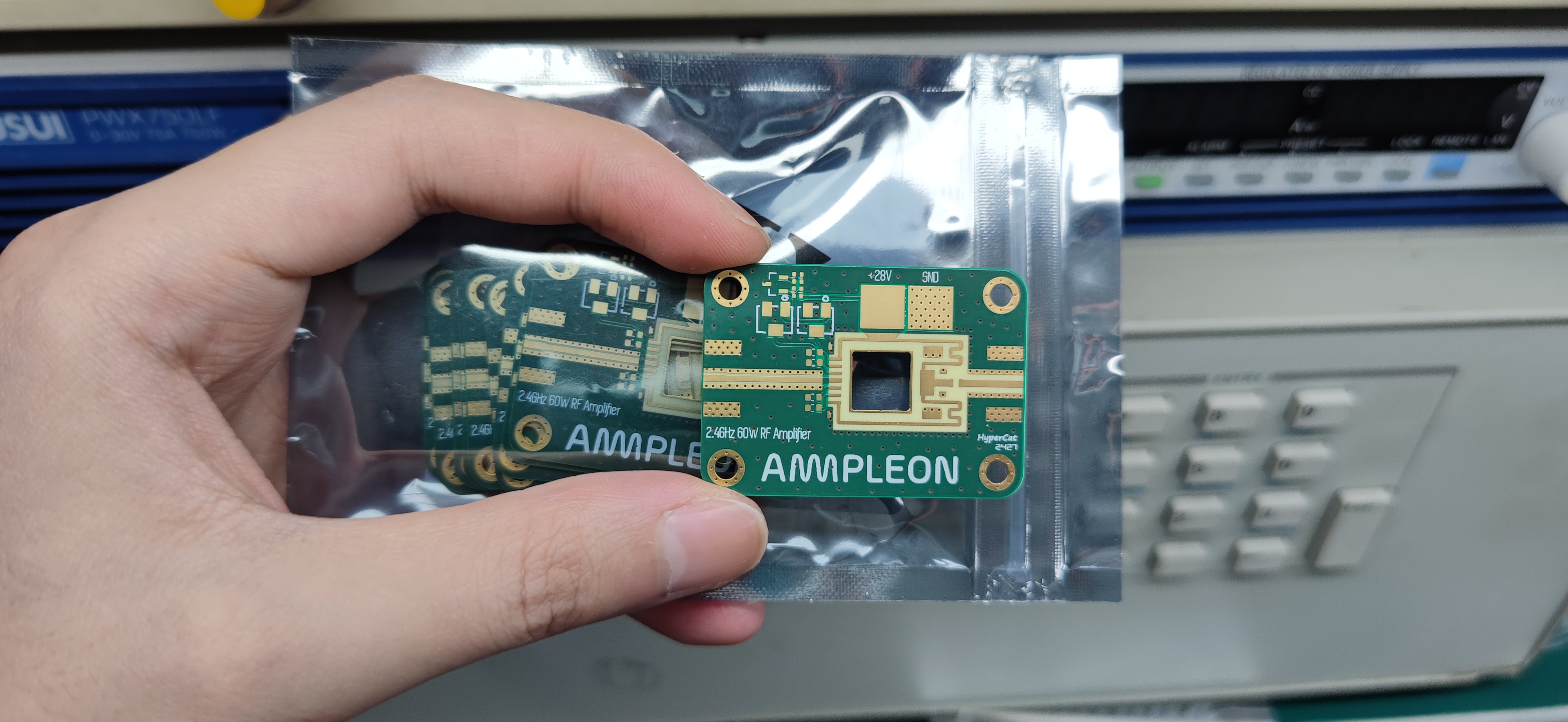
Seven: Manufacturing:
Due to the high frequency and power, the microstrip matching is designed based on the dielectric constant of the 4350. Therefore, the PCB must be made of Rogers RO4350B 0.508 board material, not FR4, otherwise there will be mismatch, severe overheating, power reduction, and in severe cases, chip burnout.
The heatsink must be made of copper, machined by CNC. Copper has good heat dissipation and is also necessary for soldering.
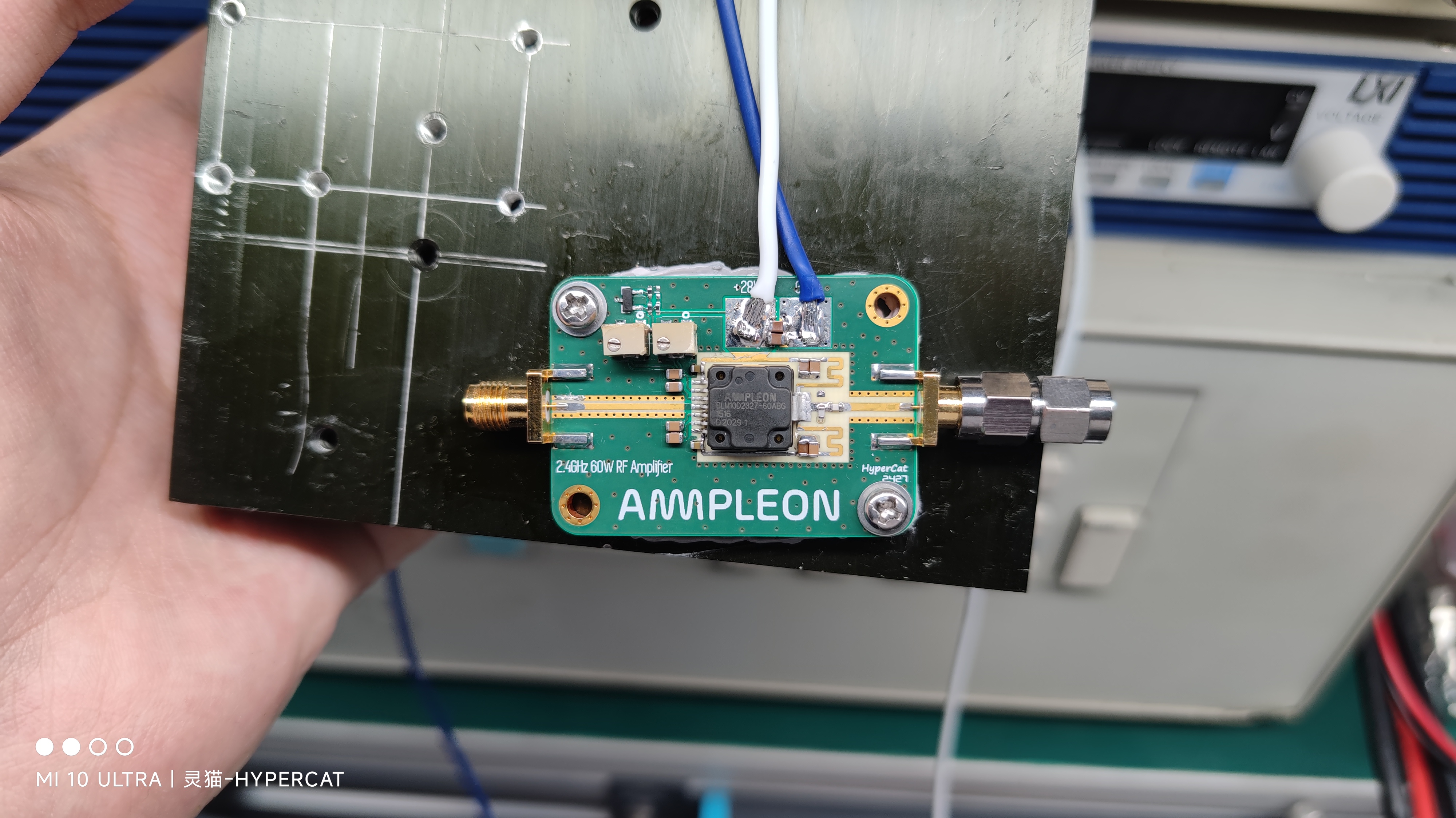
Eight: Soldering and Assembly:
1. Finished product image after soldering:

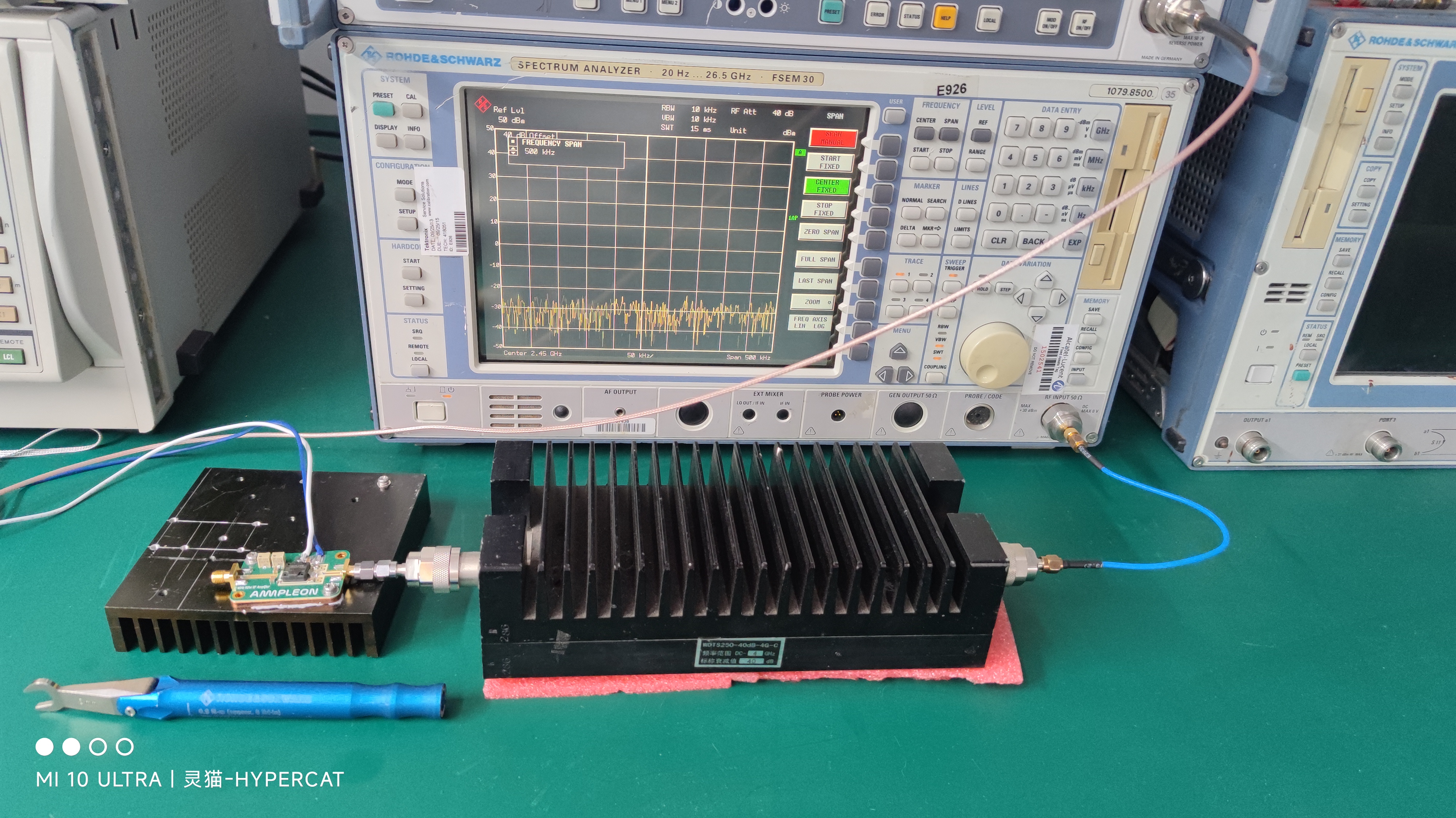
2. Assembling the heatsink and connecting the instruments:
Here, a torque wrench is needed to properly connect the amplifier board to the attenuator. Hand-tightening may not provide sufficient torque, and at this frequency and power, looseness will cause impedance abrupt changes, potentially damaging connectors or power amplifier tubes.
Gently twist the torque wrench until it bends, indicating that the torque has reached the target of 0.9 N·m. Release the wrench to allow it to automatically spring back to its original position. Remove the wrench.

The complete assembly is shown in the diagram. External 40dB 250W attenuator.
Nine: On-machine debugging:
Test instruments:
Spectrum analyzer: Rohde & Schwarz FSEM30 20Hz~26.5GHz
; Signal source: Rohde & Schwarz SMIQ03B 300KHz~3.3GHz;
Power probe: Rohde & Schwarz NRP-Z11 10MHz ~ 8GHz;
Attenuator: Huaxiang DC~4GHz 40dB 250W attenuator;
Driver stage: Self-made 700MHz~2.7GHz P1dB: +30dBm RF amplifier
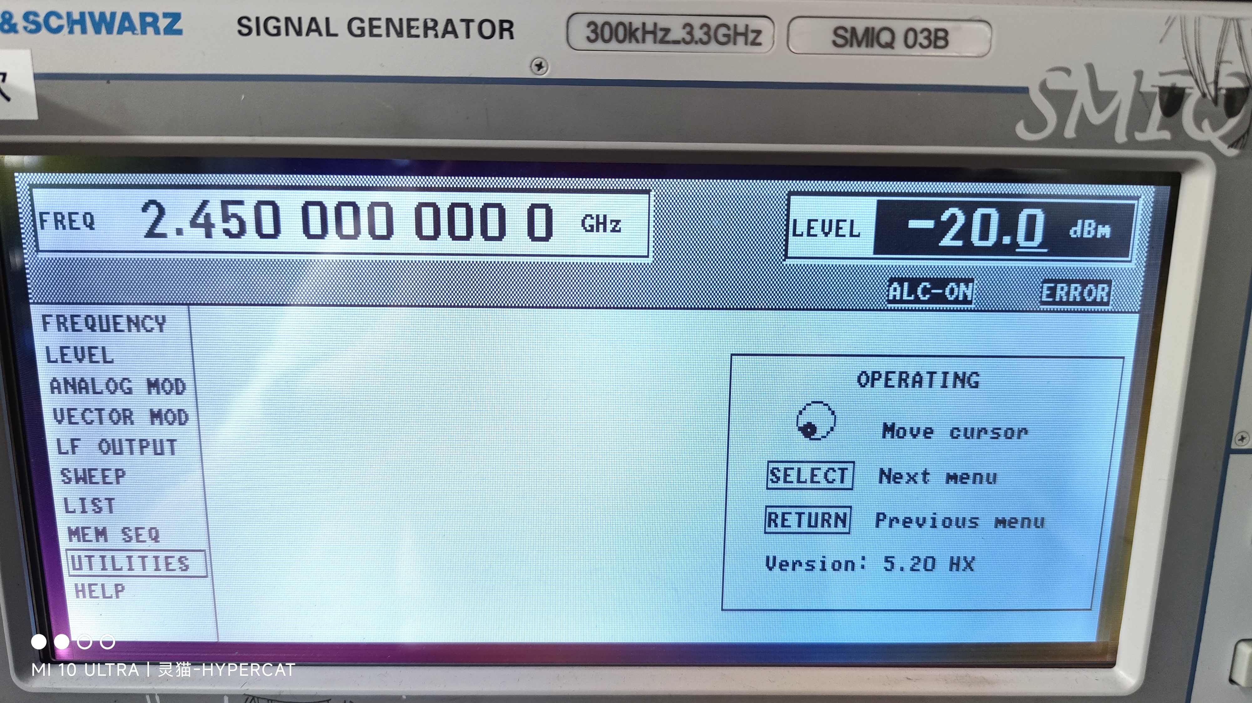
. 1. Set the signal source:
→ Output frequency: 2.45GHz (2.4G center frequency), no modulation at the point of view
→ Output power is -20dBm (to prevent over-pushing at power-on). The signal source output power will be manually and dynamically adjusted later based on actual measurement results.
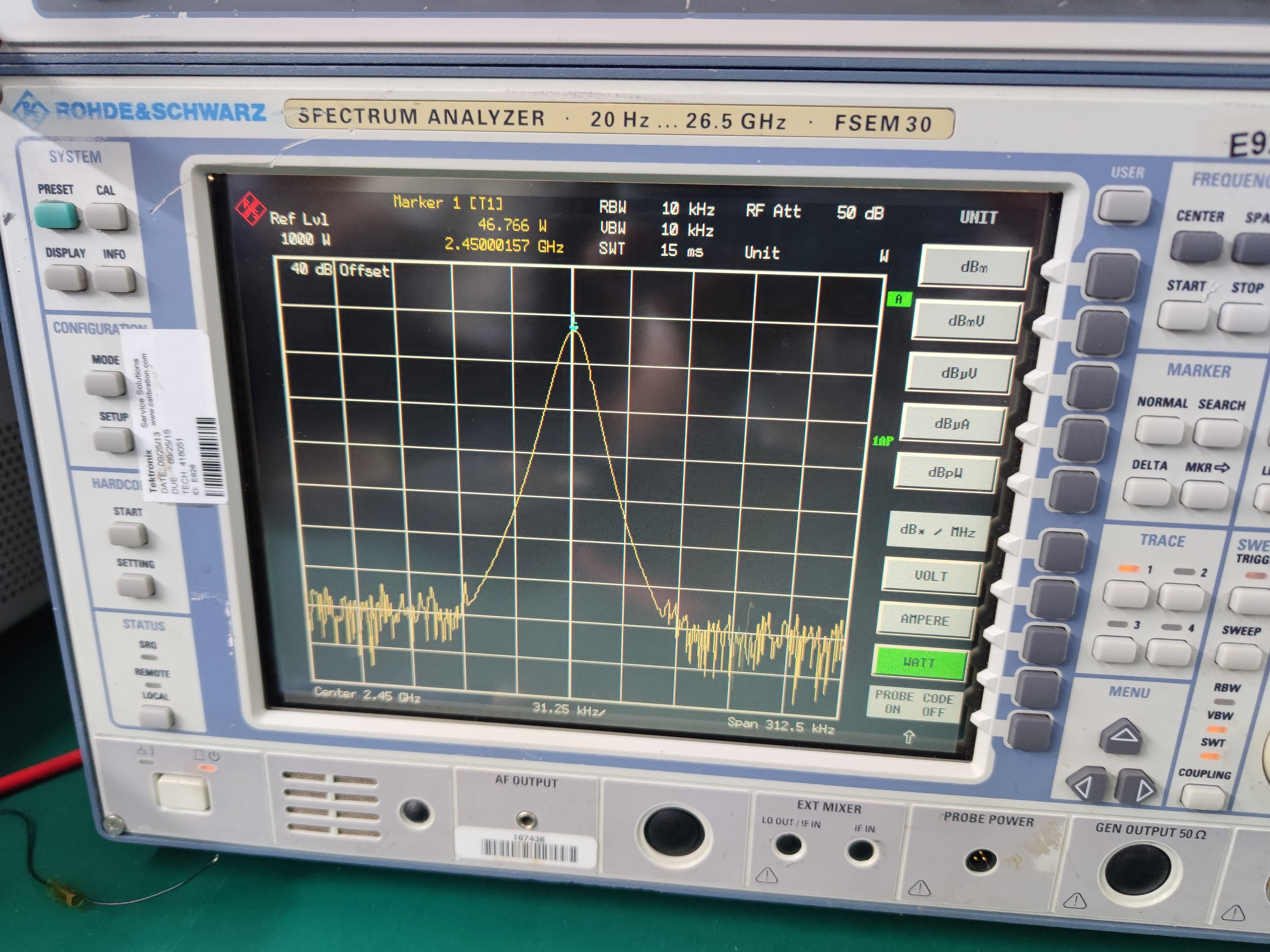
2. Setting up the spectrum analyzer:
→ Set the spectrum analyzer to CENTER: 2.45GHz. This is to place the measured spectrum peak in the center of the screen for easy observation.
→ Adjust RBW and SPAN according to the actual situation .
→ REF OFFSET 40dB (because an external 40dB attenuator is connected, the offset needs to be set here)
. → For easier power reading, we will change the display unit from dBm to W.
→ Select PEAK in MARK
as shown in the figure. The output power is approximately 47W, which is slightly lower than the 60W (pulse peak power) given in the manual. This is normal. Further adjustment of the matching should allow for a higher output.
Please correct any errors. I will humbly accept your
corrections. [THE END]


 京公网安备 11010802033920号

 74LCX16541


