Project Introduction
This project is a learning expansion board I created using some existing modules and based on the LCSC Skystar high-end version.
Project Functions
This project includes the following functions (the attached table contains specific pin usage):
Matrix button
serial port 3 leads out
4 IO leads out
8 LEDs
2 ADC module interfaces
Infrared remote control decoder interface
DS18B20/DHT11 interface
0.96-inch OLED interface
MPU6050 interface
8-digit digital tube
passive buzzer
2 servo motor drive interfaces
TB6612 module and 2 motor drive interfaces controlled by TB6612
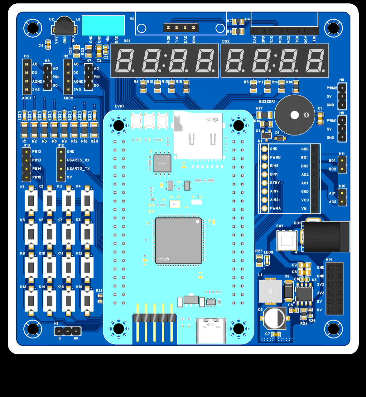
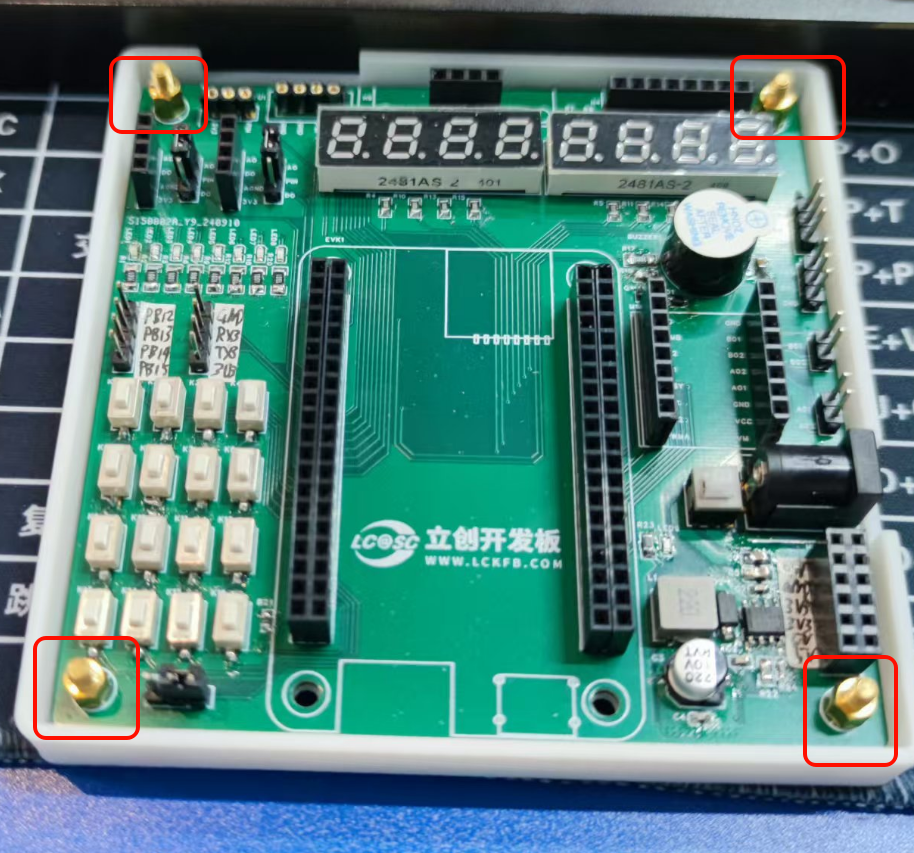
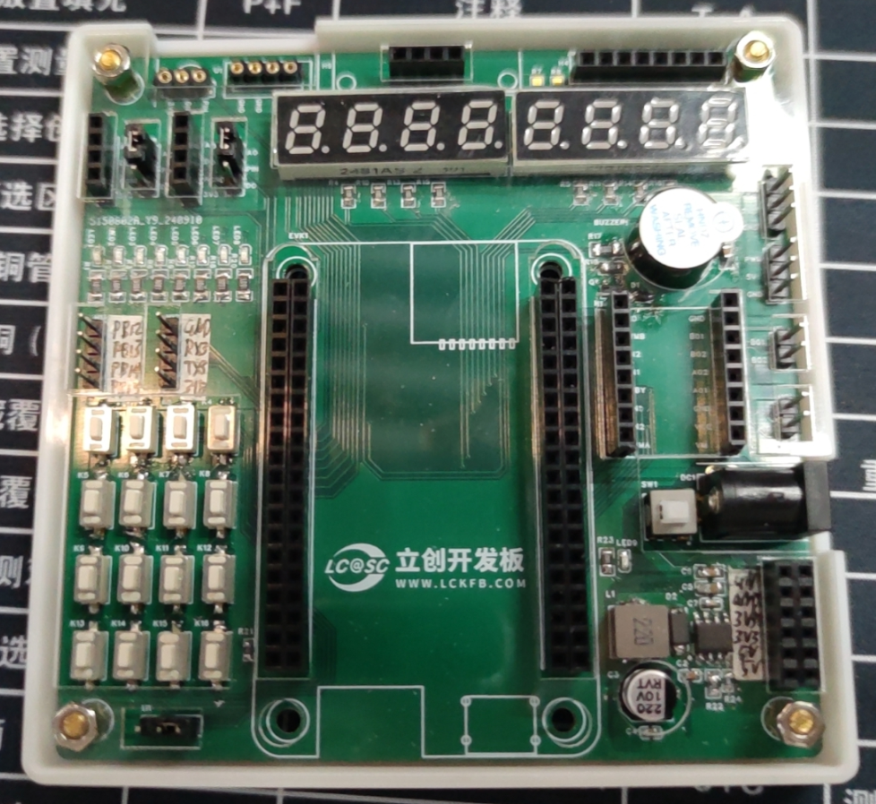
Actual Photos

3D Drawings
Note: Some modifications and additions have been made to the silkscreen and circuit, so there are some inconsistencies with the actual product images.
Hardware Specifications
The attached table contains specific pin usage
Power Supply
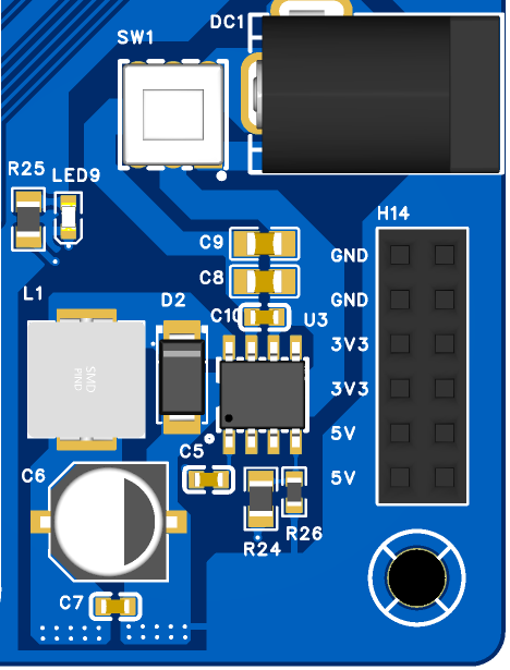
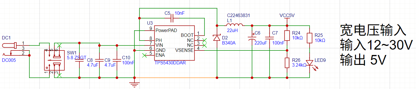
Since it needs to drive some small motors, a DC-DC power supply is used. Refer to the chip datasheet for recommended circuits and add filter capacitors.
Note: Using a charger with a partial output of 12V 1A may cause a restart when driving a DC motor. The H1 interface in the
matrix button


circuit diagram can switch between 16 matrix buttons and 4 independent buttons by shorting the terminal.
Serial port 3 leads and IO leads

are provided for easy connection to other modules.
The 8 LEDs

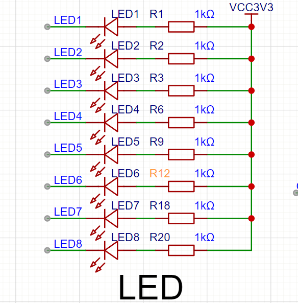
use the same group of GPIOs for easy control of
the 2 ADC modules.
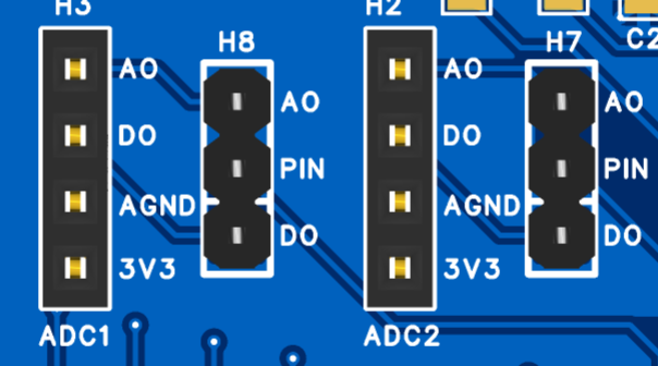
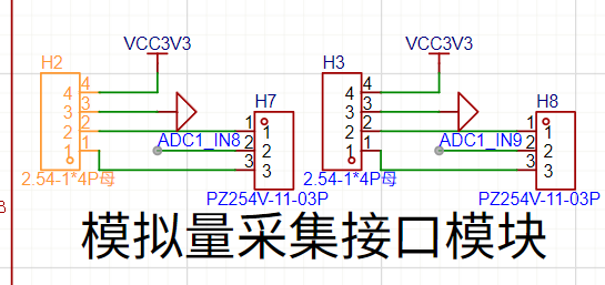
Considering that commonly used module interfaces include both digital and analog outputs, H8 and H7 interfaces are added for switching.
The infrared remote control decoder interface
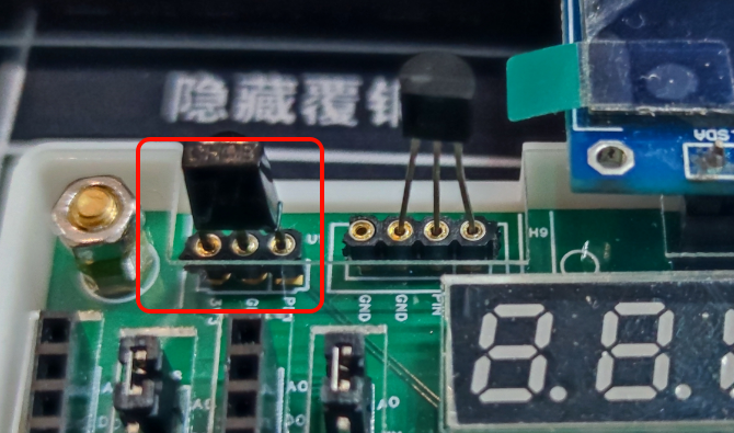

uses a single row of round-hole female connectors for easy replacement
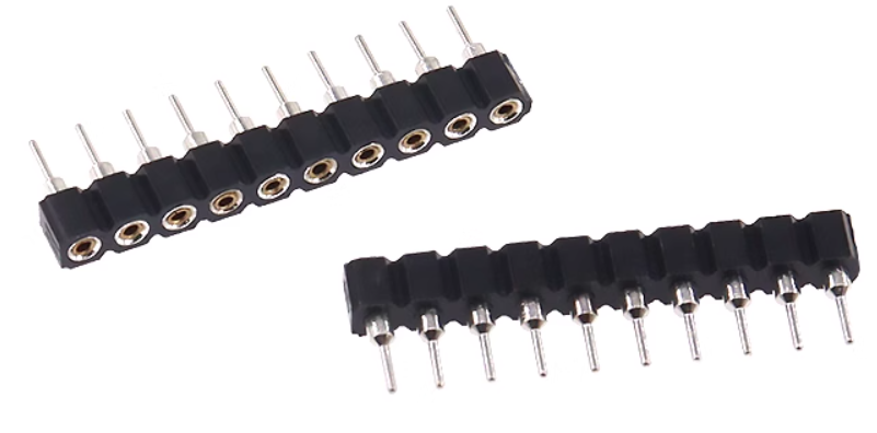
of the DS18B20/DHT11 interface.

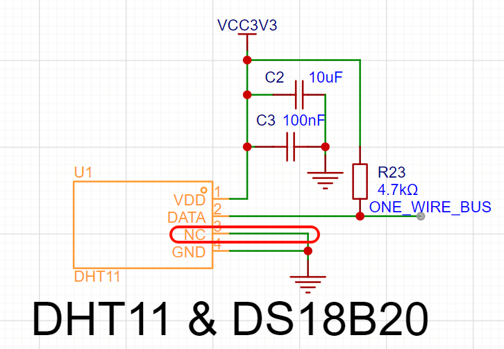
By grounding the empty pin 3 of the DHT11, it can be adapted to the DS18B20. Round-hole female connectors are also used for easy switching.
The 0.96-inch OLED interface and MPU6050 interface

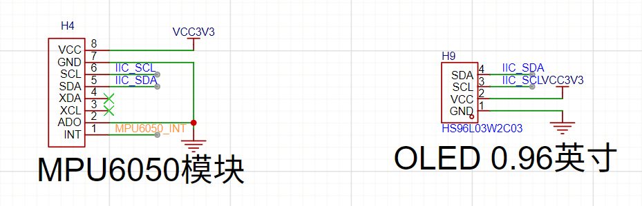
use the same IIC connection
. The segment selection and digit selection of the digital tube
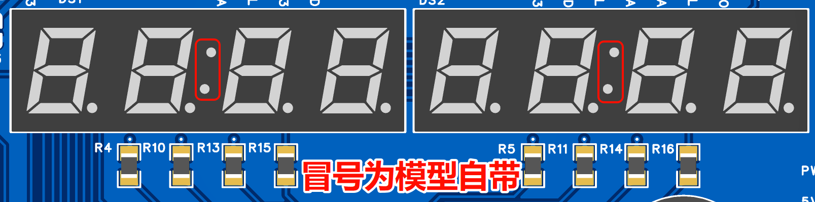
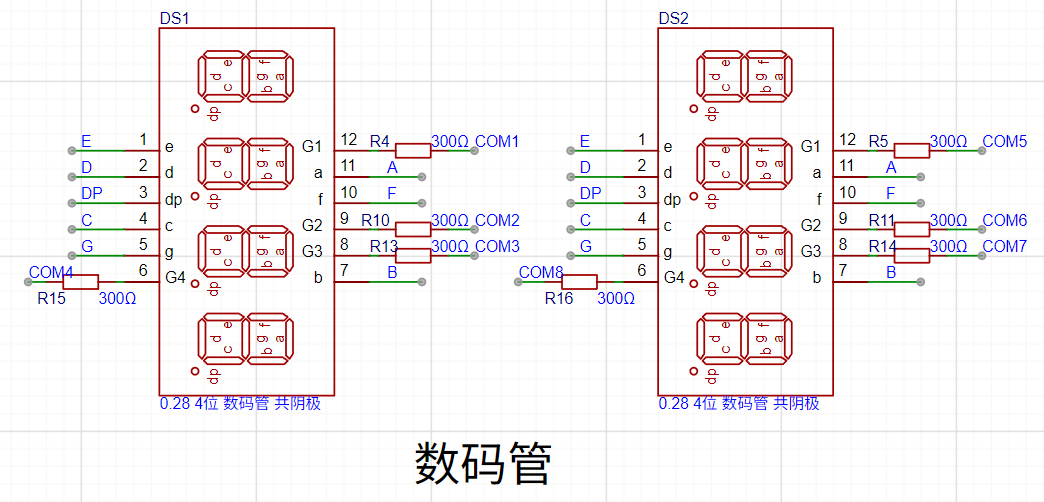
use the same group of I/O, arranged sequentially for easy programming. The
passive buzzer
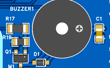

used is a 12mm diameter passive buzzer; the connected I/O ports can reuse timers.
Two servo drive interfaces
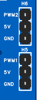
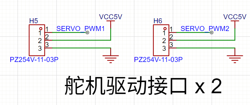
can be directly used to drive servo motors.
The TB6612 module and two motor drive interfaces controlled by the TB6612 are also
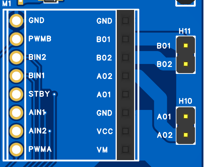
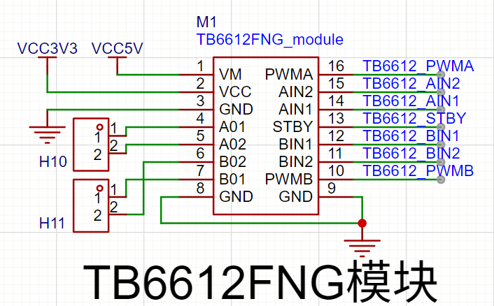
included. A dual-channel DC motor drive module connects all controllable pins to the core board for control. Example
software code
is attached; only basic driver
code is implemented. The character encoding used in the project is UTF-8. If Chinese characters are garbled, please switch
the encoding in the settings. Detailed
example code is included
. Directory structure: Project folder
├── BSP //Extension board driver code directory│
├── Inc
│ │ ├── bsp_adc.h //ADC driver code│
│ ├── bsp_buzzer.h //Buzzer driver code│
│ ├── bsp_ds18b20.h //DS18B20 driver code│
│ ├── bsp_iic.h // Software IIC driver code│
│ ├── bsp_infrared.h // Infrared decoding driver code│
│ ├── bsp_key.h // Button driver code│
│ ├── bsp_led.h // LED driver code│
│ ├── bsp_mpu6050.h // MPU6050 driver code, depends on bsp_iic.h
│ │ ├── bsp_nixie.h // Digital tube driver code│
│ ├── bsp_oled.h // OLED driver code, depends on bsp_iic.h
│ │ ├── bsp_oledbmp.h // OLED image array│
│ ├── bsp_oledfont.h // OLED character array│
│ ├── bsp_servo.h // Servo driver code│
│ ├── bsp_tb6612.h //Driver code for TB6612 controlling DC motors│
│ └── bsp_w25q128.h //Driver code for core board W25Q128│
└── Src
│ ├── bsp_adc.c
│ ├── bsp_buzzer.c
│ ├── bsp_ds18b20.c
│ ├── bsp_iic.c
│ ├── bsp_infrared.c
│ ├── bsp_key.c
│ ├── bsp_led.c
│ ├── bsp_mpu6050.c
│ ├── bsp_nixie.c
│ ├── bsp_oled.c
│ ├── bsp_oledbmp.c
│ ├── bsp_oledfont.c
│ ├── bsp_servo.c
│
├── bsp_tb6612.c │ └── bsp_w25q128.c
├── Drivers //HAL library driver code├──
Core
├── MDK-ARM
├── keilkill.bat //Compilation intermediate file cleanup script└──
sky_star_Expansion_board.ioc //STM32CubeMX project
main function call code
example. Use the code in the main loop, uncomment it to use
/* USER CODE BEGIN 2 */
char str[50];
MYIIC_Init();
MYADC_Init();
OLED_Init();
SERVO_Init();
TB6612_Init();
IR_Init();
MPU6050_Init();
OLED_DisplayTurn(1);
KEY_ModeChange(0);
/* USER CODE END 2 */
/* Infinite loop */
/* USER CODE BEGIN WHILE */
while (1)
{
//uart & DS18B20 example
sprintf(str, "%.2f
", DS18B20_GetTemperture());
HAL_UART_Transmit(&huart1, (uint8_t*)str, strlen(str), 50);
HAL_Delay(100);
//buzzer example
for (uint16_t i = 0; i <= 2000; i += 200)
{
Buzzer_Cfg(i,50);
Buzzer_Use(1);
HAL_Delay(1000);
Buzzer_Use(0);
HAL_Delay(1000);
}
//led Example
for (uint8_t i = 1; i <= 8; ++i)
{
Led_On(i);
HAL_Delay(50);
Led_Off(i);
HAL_Delay(50);
}
//ADC example
MYADC_GetVal();
sprintf(str, "adc1:%f", MYADC_adc1Valf);
OLED_ShowString(0, 0, (uint8_t *)str, 16, 1);
sprintf(str, "adc2:%f", MYADC_adc2Valf);
OLED_ShowString(0, 16, (uint8_t *)str, 16, 1);
OLED_Refresh();
//key example
if (KEY_flag == 1 && KEY_GetState(1))
OLED_ShowChar(0, 0, '1', 16, 1);
if (KEY_flag == 1 && KEY_GetState(2))
OLED_ShowChar(8, 0, '2', 16, 1);
if (KEY_flag == 1 && KEY_GetState(3))
OLED_ShowChar(16, 0, '3', 16, 1);
if (KEY_flag == 1 && KEY_GetState(4))
OLED_ShowChar(24, 0, '4', 16, 1);
if (KEY_flag == 1 && KEY_GetState(5))
OLED_ShowChar(32, 0, '5', 16, 1);
if (KEY_flag == 1 && KEY_GetState(6))
OLED_ShowChar(40, 0, '6', 16, 1);
if (KEY_flag == 1 && KEY_GetState(7))
OLED_ShowChar(48, 0, '7', 16,1);
if (KEY_flag == 1 && KEY_GetState(8))
OLED_ShowChar(56, 0, '8', 16, 1);
if (KEY_flag == 1 && KEY_GetState(9))
OLED_ShowChar(64, 0, '9', 16, 1);
if (KEY_flag == 1 && KEY_GetState(10))
{
sprintf(str, "10");
OLED_ShowString(72, 0, (uint8_t *)str, 16, 1);
}
if (KEY_flag == 1 && KEY_GetState(11))
{
sprintf(str, "11");
OLED_ShowString(88, 0, (uint8_t *)str, 16, 1);
}
if (KEY_flag == 1 && KEY_GetState(12))
{
sprintf(str, "12");
OLED_ShowString(0, 16, (uint8_t *)str, 16, 1);
}
if (KEY_flag == 1 && KEY_GetState(13))
{
sprintf(str, "13");
OLED_ShowString(16, 16, (uint8_t *)str, 16, 1);
}
if (KEY_flag == 1 && KEY_GetState(14))
{
sprintf(str, "14");
OLED_ShowString(32, 16, (uint8_t *)str, 16, 1);
}
if (KEY_flag == 1 && KEY_GetState(15))
{
sprintf(str, "15");
OLED_ShowString(48, 16, (uint8_t *)str, 16, 1);
}
if (KEY_flag == 1 && KEY_GetState(16))
{
sprintf(str, "16");
OLED_ShowString(64, 16, (uint8_t *)str, 16,1);
}
OLED_Refresh();
//servo example
for (uint8_t i = 0; i < 180; i+=5)
{
if (i < 90)
SERVO_Ch2Angle(i);
else
SERVO_Ch1Angle(i);
}
HAL_Delay(100);
OLED_Refresh();
//TB6612 control DC motor example
TB6612_Pwm1Mode(TB6612_MotorFWD);
TB6612_Pwm2Mode(TB6612_MotorFWD);
for (uint8_t i = 0; i < 100; i+=5)
{
TB6612_Pwm1Duty(i);
TB6612_Pwm2Duty(i);
HAL_Delay(100);
}
TB6612_Pwm1Mode(TB6612_MotorBRK);
TB6612_Pwm2Mode(TB6612_MotorBRK);
HAL_Delay(200);
TB6612_Pwm1Mode(TB6612_MotorREV);
TB6612_Pwm2Mode(TB6612_MotorREV);
for (uint8_t i = 0; i < 100; i+=5)
{
TB6612_Pwm1Duty(i);
TB6612_Pwm2Duty(i);
HAL_Delay(100);
}
TB6612_Pwm1Mode(TB6612_MotorBRK);
TB6612_Pwm2Mode(TB6612_MotorBRK);
TB6612_AllClose();
HAL_Delay(200);
OLED_Refresh();
//MPU6050 Example
MPU6050_ReadGyro();
MPU6050_ReadAcc();
sprintf(str, "GX%5d AX%5d", MPU6050_gyroX, MPU6050_accX);
OLED_ShowString(0, 0, (uint8_t *)str, 16, 0);
sprintf(str, "GY%5d AY%5d", MPU6050_gyroY, MPU6050_accY);
OLED_ShowString(0, 16, (uint8_t *)str, 16, 0);
sprintf(str, "GZ%5d" AZ%5d", MPU6050_gyroX, MPU6050_accZ);
OLED_ShowString(0, 32, (uint8_t *)str, 16, 0);
OLED_Refresh();
//Infrared remote control example
sprintf(str, "%3d %3d %3d %3d", IR_data[0], IR_data[1], IR_data[2], IR_data[3]);
OLED_ShowString(0, 0, (uint8_t *)str, 16, 1);
sprintf(str, "%3x %3x %3x %3x %3d", IR_data[0], IR_data[1], IR_data[2], IR_data[3], IR_repeatCnt);
OLED_ShowString(0, 16, (uint8_t *)str, 16, 1);
sprintf(str, "%3d", IR_repeatCnt);
OLED_ShowString(0, 32, (uint8_t *)str, 16, 1);
OLED_Refresh();
/* USER CODE END WHILE */
/* USER CODE BEGIN 3 */
}
Note:
The output of the part used is 12V 1A The charging head may restart when driving a DC motor.
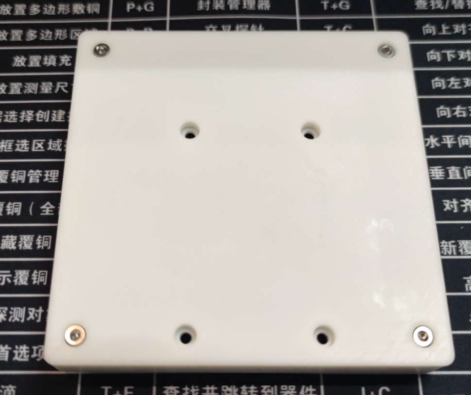
This project only uses the bottom shell, using acrylic material instead of the top shell. See the assembly process for details.
Assembly Process
: Required parts:
1 white 3D printed bottom shell,

1 acrylic panel from the LCEDA project, 4

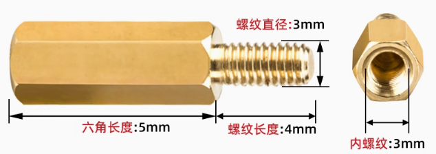
M3x6 screws from the LCEDA project, and

M3 * 5 + 4 hexagonal copper pillars. Assemble the bottom shell, insert the screws , place the PCB from the front, and secure it with the hexagonal copper pillars . Cover with the acrylic cover and tighten the nuts. Actual product image.


Project code.zip
LCSC-SkyStar-Pin Assignment Table.xlsx
Demo video.mp4
PDF_LCSC SkyStar Development Board Expansion Board_Learning Expansion Board.zip
Altium_LCSC SkyStar Development Board Expansion Board_Learning Expansion Board.zip
PADS_LCSC Skystar Development Board Expansion Board_Learning Expansion Board.zip
91627
217 - GL3224 Card Reader: Understanding and Design Case
This card reader, based on the GL3224-32PIN version,
draws inspiration from various open-source projects, supplements and shares my own test data and design considerations.
Video Links:
Bilibili Video -- Production Process and Design Interpretation
Project Introduction
First, here are the projects I referenced:
https://oshwhub.com/scarrr0725/gl3224
https://oshwhub.com/Axin/3-0-du-ka-qi-ji-yu-gl3224-zhi-chi-xiang-ji-sd-ka
https://oshwhub.com/shadow27/ji-yu-gl3224-di-usb3-0-du-ka-qi
My QQ groups: 874577320, 232586710, 345731137
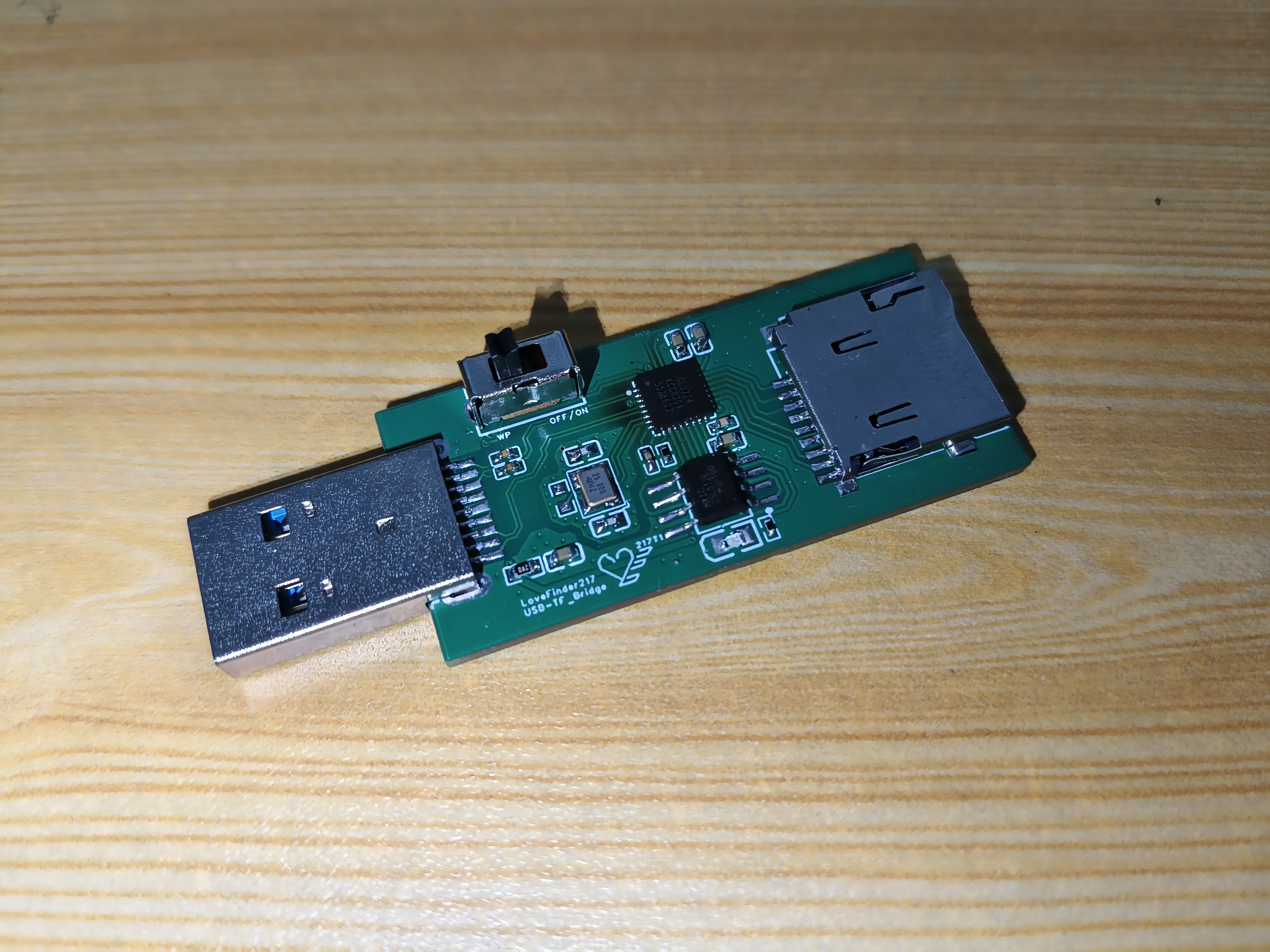
This card reader based on the GL3224-32PIN version
absorbs and draws inspiration from various open-source projects, supplementing and sharing my own test data and design considerations.
Project Functionality and Performance Testing
TF card read/write function, can be read and written by directly connecting to the computer via USB-A male connector.
Performance test chart: (Test date: October 17, 2024, afternoon) ( Using an unknown 64G memory card)

The image above shows the device before firmware upgrade.
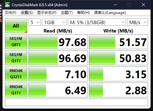
The image above shows the device after firmware upgrade. However, this test is incomplete, with insufficient number of tests and is for reference only!
Actual testing shows support for 128G SD cards (in other designs, the same chip and peripherals are used).
Project parameters
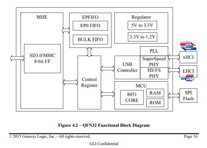
: The main controller is GL3224, QFN32 version. The QFN48 version is not discussed here, but the latter should have the ability to read and write to two cards simultaneously.
Principle analysis (hardware description):
Connect the chips directly according to the chip block diagram and various open-source materials.
Chip input terminals: two PHYs, one USB2, one USB3@5Gbps.
Regarding firmware
: After incomplete testing, the chip's built-in 1532 firmware is not inferior to the 1536 in performance. The physical transmission of USB3 is not a problem. However, I have still included the firmware tool in the attachment. The firmware tool's config.ini also provides more supported memory chips not mentioned in the official documentation.
Basic requirements for memory chips: The memory chip used must have at least 512Kbit

. The upgrade tool is shown in the image below. After soldering, power on and open the software. Click "start" to upgrade.

Notes:
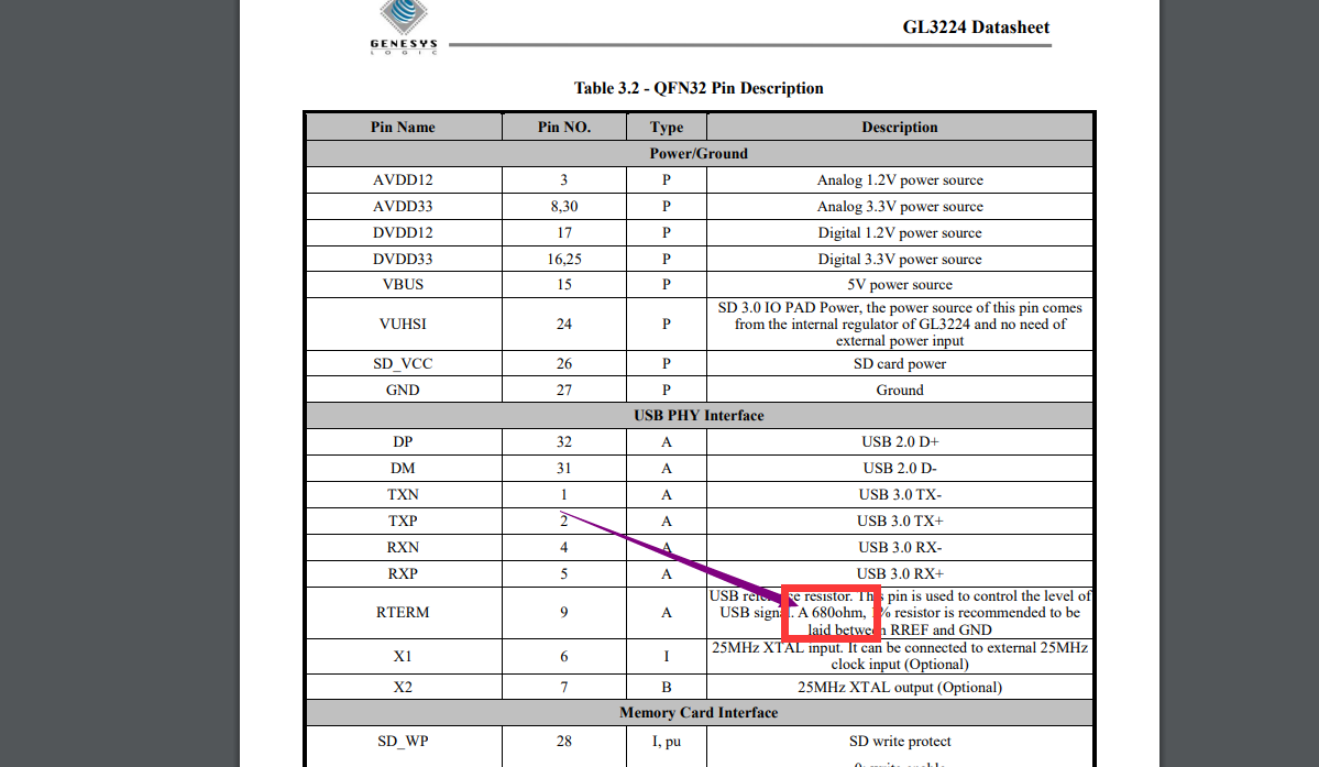
REXT currently has two available values: 680R (official datasheet recommends 680R) and 1K (also available). I recommend the former.
When replicating, it's suggested to place capacitors close to the chip pins, ideally on the back of the chip, to facilitate signal and power separation.
It's also recommended to ground the crystal oscillator to reduce interference with the USB3 differential pair.
The capacitor reserved for the crystal oscillator varies depending on the actual crystal being soldered, typically around 10-20pF.
If one side is close to 0V and the other is 3.3V, the crystal oscillator is definitely not functioning correctly!
Actual testing shows it generates considerable heat during operation. It's recommended to use a DC-DC independent power supply for the TF card during replication. Most TF cards can withstand 3-4.2V input (don't try 5V).
Write protection is disabled by grounding the pin on the toggle switch. This pin has an internal pull-up, so leaving this pin floating enables write protection. (
Image of actual product)


GL3224 Upgrade Tool - Upgrade to version 1536.7z
official REXT value.png
PDF_217 - GL3224 Card Reader Explanation and Design Case.zip
Altium_217 - GL3224 Card Reader: Understanding and Design Cases.zip
PADS_217 - GL3224 Card Reader: Understanding and Design Cases.zip
BOM_217 - GL3224 Card Reader Interpretation and Design Case.xlsx
91628
electronic


 京公网安备 11010802033920号

 DF17C-40DP-0.5V


