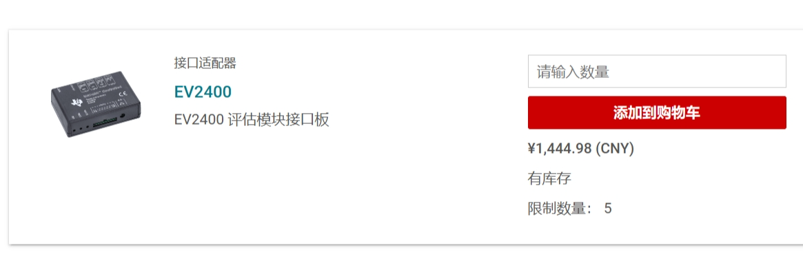
 , fortunately, TI has released the EV2400 schematic, allowing us to purchase a relatively inexpensive one on Taobao/Xianyu. Alternatively, if you prefer not to be priced too high or enjoy tinkering, building your own is a good option. This project provides a verified, well-protected, original-factory-compatible, compact, and aesthetically pleasing DIY EV2400 solution.
 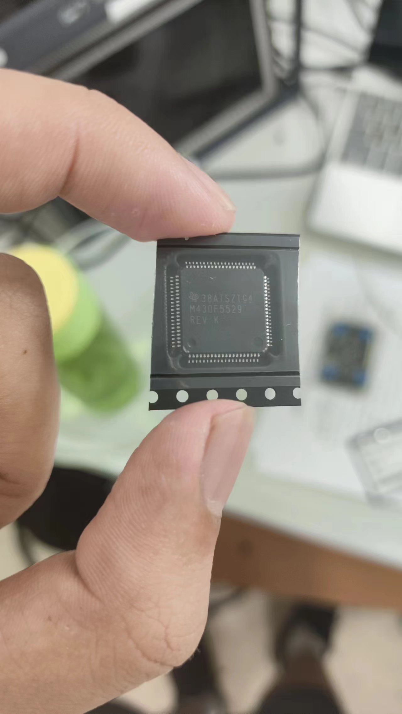 (Note: Some people online have also found that the F5528 (average price around 10 yuan) can be used as a substitute, and there are related solutions. However, I have also verified this. I bought four chips from different stores, and they either had no core voltage, the crystal oscillator didn't oscillate, or they could only be flashed but couldn't run. There are too many bad products. I spent 40 or 50 yuan on chips but didn't get a single usable one. It's better to just use the 5529, at least genuine ones are easier to find.)
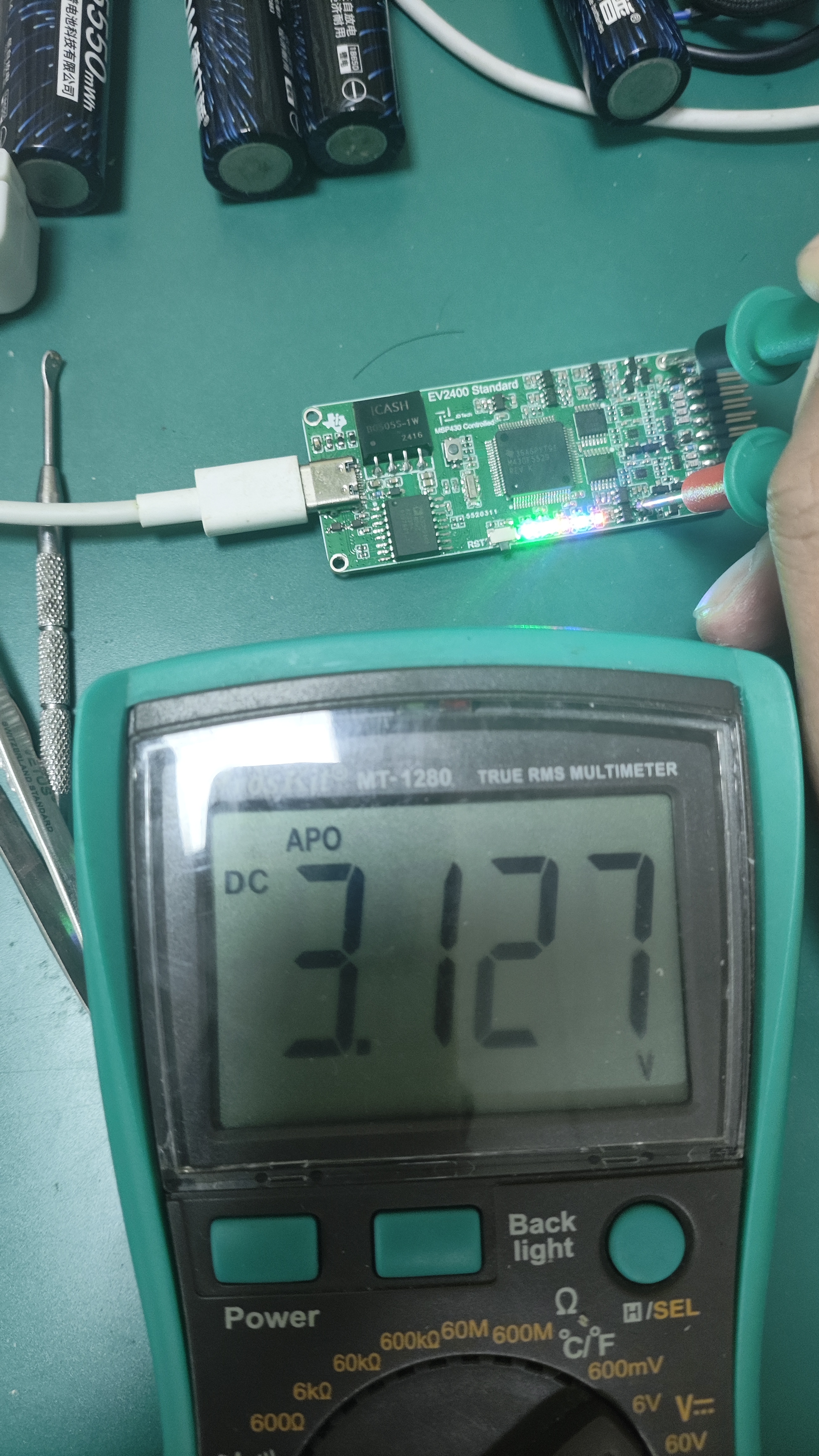
 However, it's worth noting that some unofficial sources I consulted stated that a non-adjustable reference level (such as the fixed 3.3V reference level used in most lightweight EV2400s on the market) might damage the chip being debugged. However, in my humble opinion, TI, as one of the world's leading analog chip design and manufacturing companies, would certainly consider various application environments. Moreover, the internal block diagram of the chip provided by TI (using the BQ4050 as an early representative) shows that the chip's data interface uses a logic gate buffer circuit between the internal CPU (as shown in the figure)
 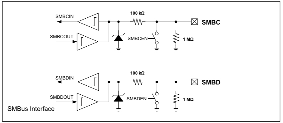 , and in many designs, the MCU with a 3.3V reference level communicates directly with the battery protection chip without any chip damage observed. ) In the worst-case scenario, furthermore, according to the recommended operating conditions in section 6.3 of the BQ4050 datasheet, the maximum withstand voltage for the SMC and SMD interfaces is 26V (as shown in the figure).
 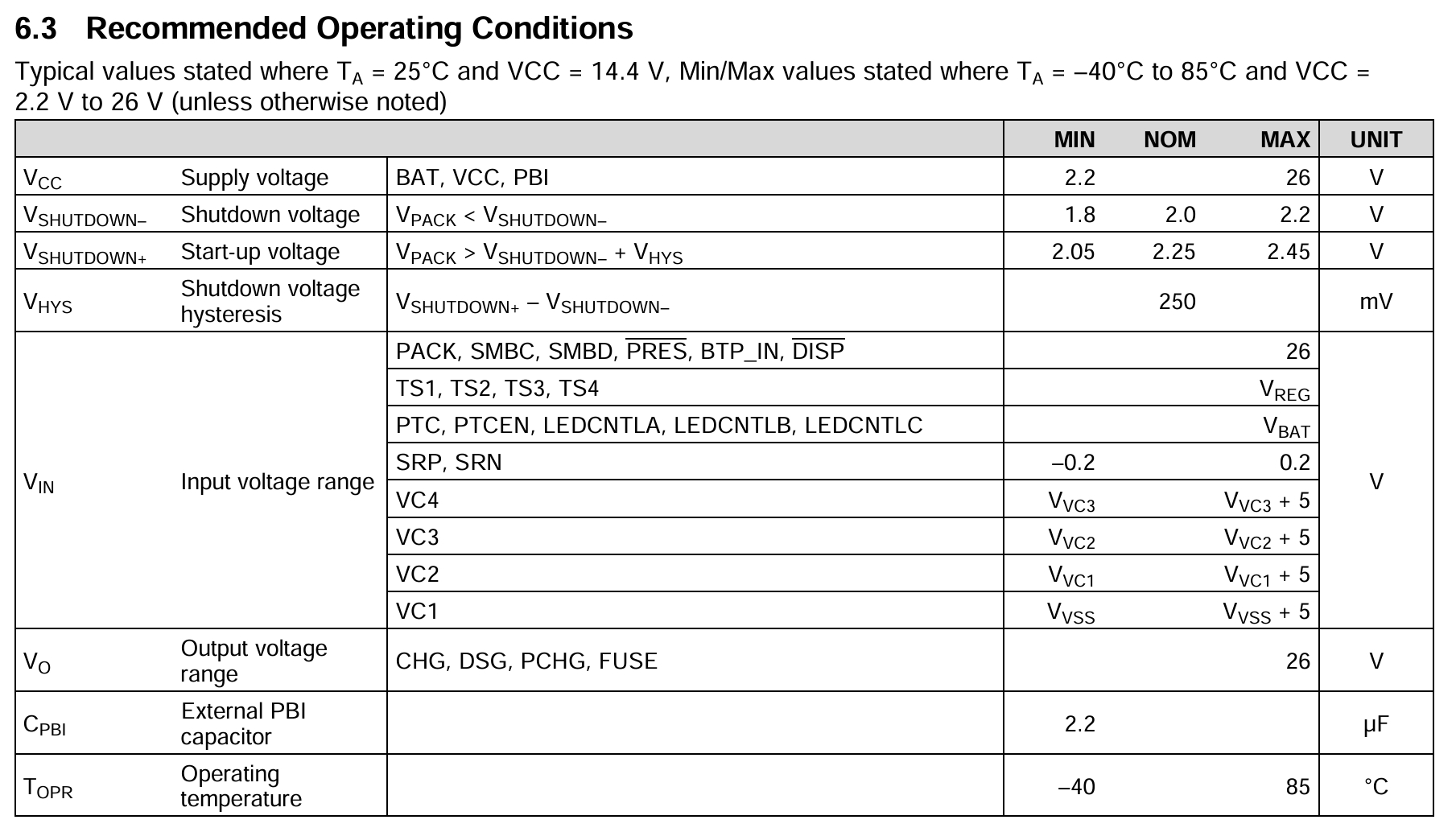 Meanwhile, another TI battery fuel gauge and protection chip, the BQ40Z80, integrates a lightweight EV2400 on its EVM. The official schematic shows that its interface does not use a level conversion IC with the fuel gauge IC interface, but only a few pull-up and pull-down resistors (as shown in the figure). Research indicates that the BQ40Z80's internal CPU also uses a 1.8V power supply, indicating that it has internal level conversion circuitry and can operate at 3.3V. Therefore
 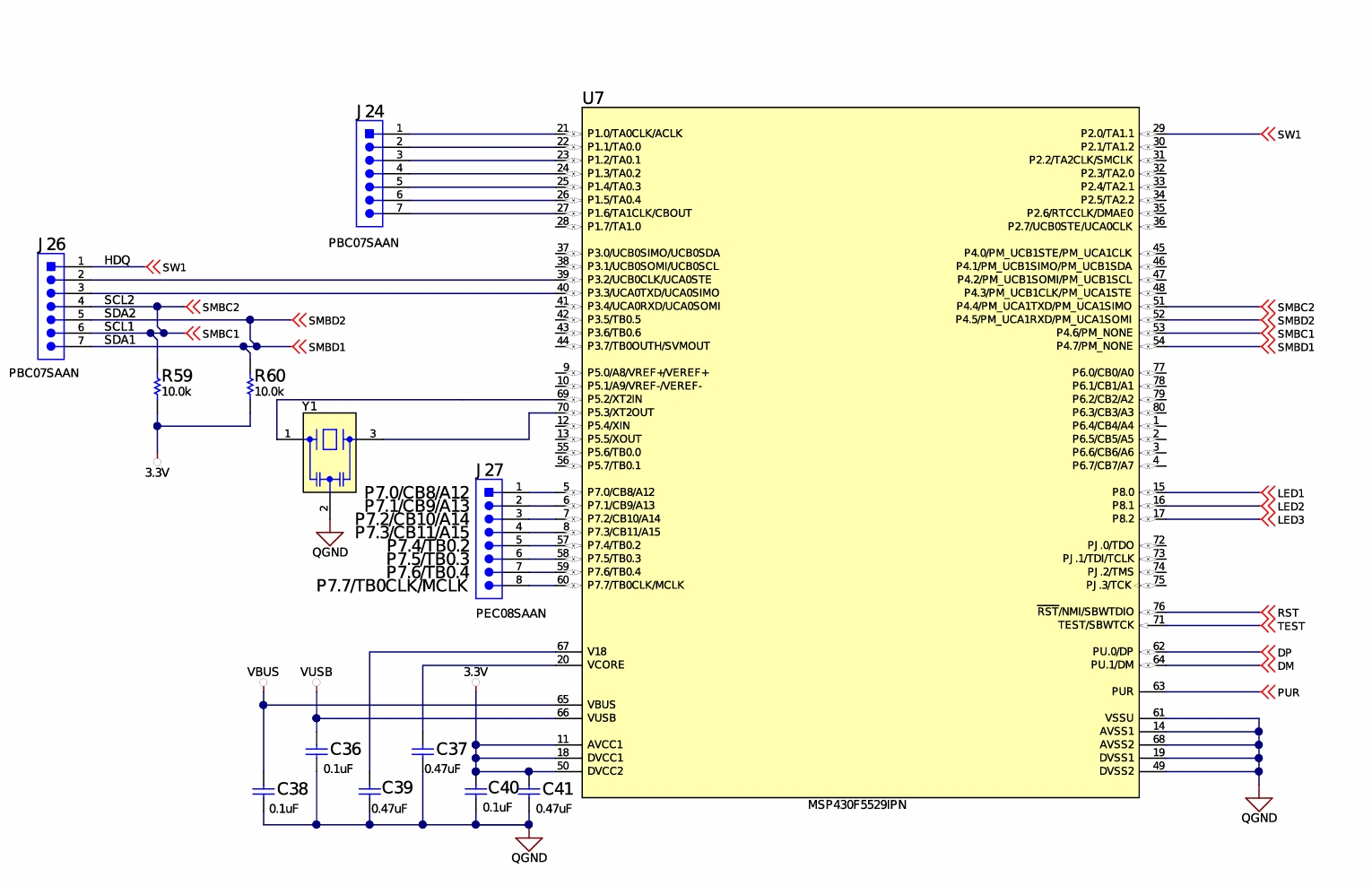 , the conclusion that cheap debuggers/fixed reference level debuggers will damage the chip, and the assertion that some debuggers made with the 5528 chip are defective and can damage the chip (the specific reasons are explained in this project: [Verified] EV2400-Lite is based on F5528 [Replicating is not recommended]) The conclusion regarding the LCSC open-source hardware platform (oshwhub.com) may be a deliberate misrepresentation by vendors to justify higher prices. The debug level of TI's official debugger is almost identical to 3.3V; the cheaper debugger lacks features like series current and electrostatic discharge (ESD) protection. For drone enthusiasts/developers looking to save costs, cheaper debuggers are perfectly usable, though they come at the cost of lacking protection. While
 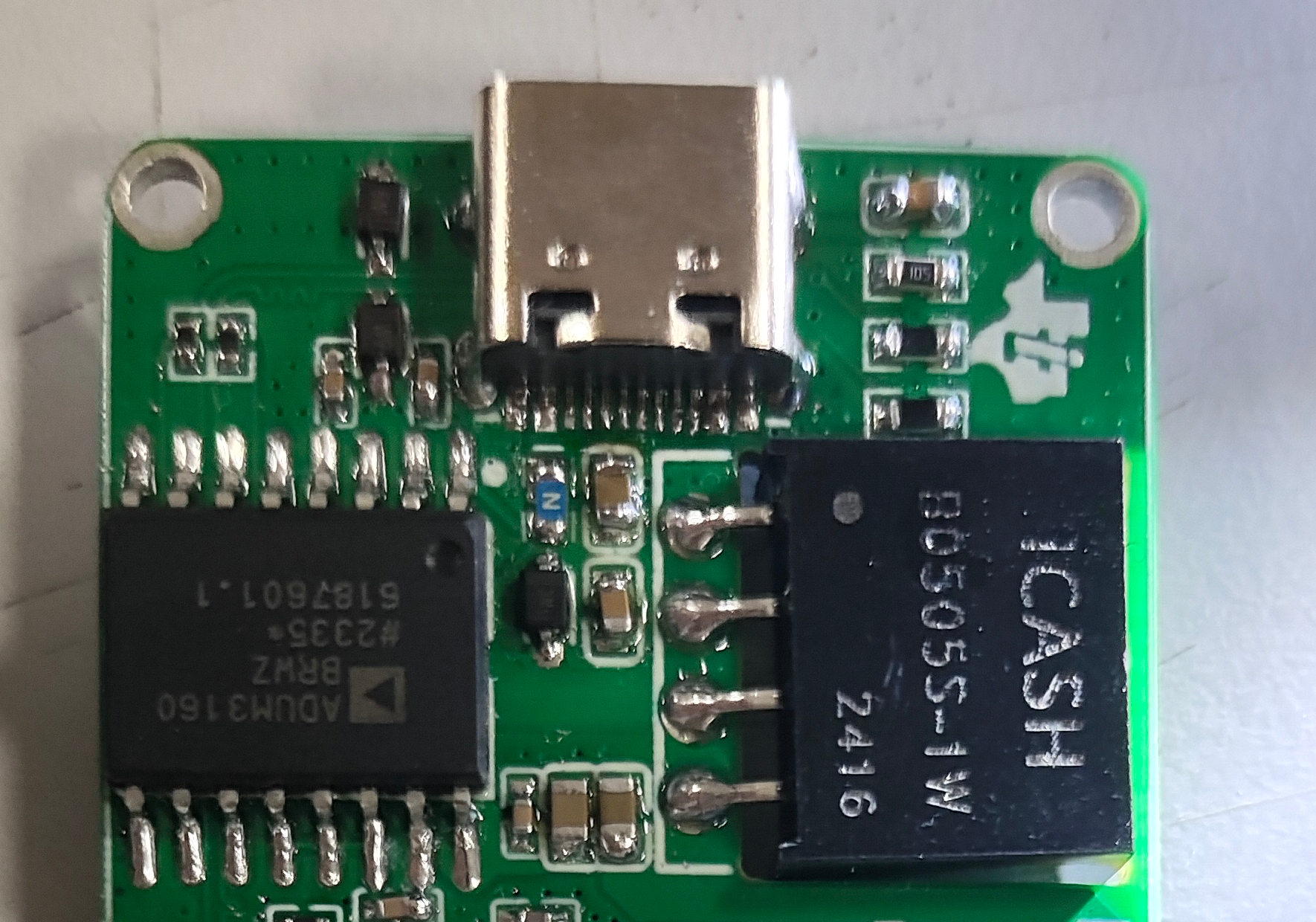 2. PCB Design:
  (A side note: while browsing the MSP manual recently, I found some tutorials from TI on porting STM chip programs to MSP series microcontrollers—poaching ST's talent, haha!) It's true what they say, red and blue are a perfect match! ヾ(≧▽≦*)o) Since
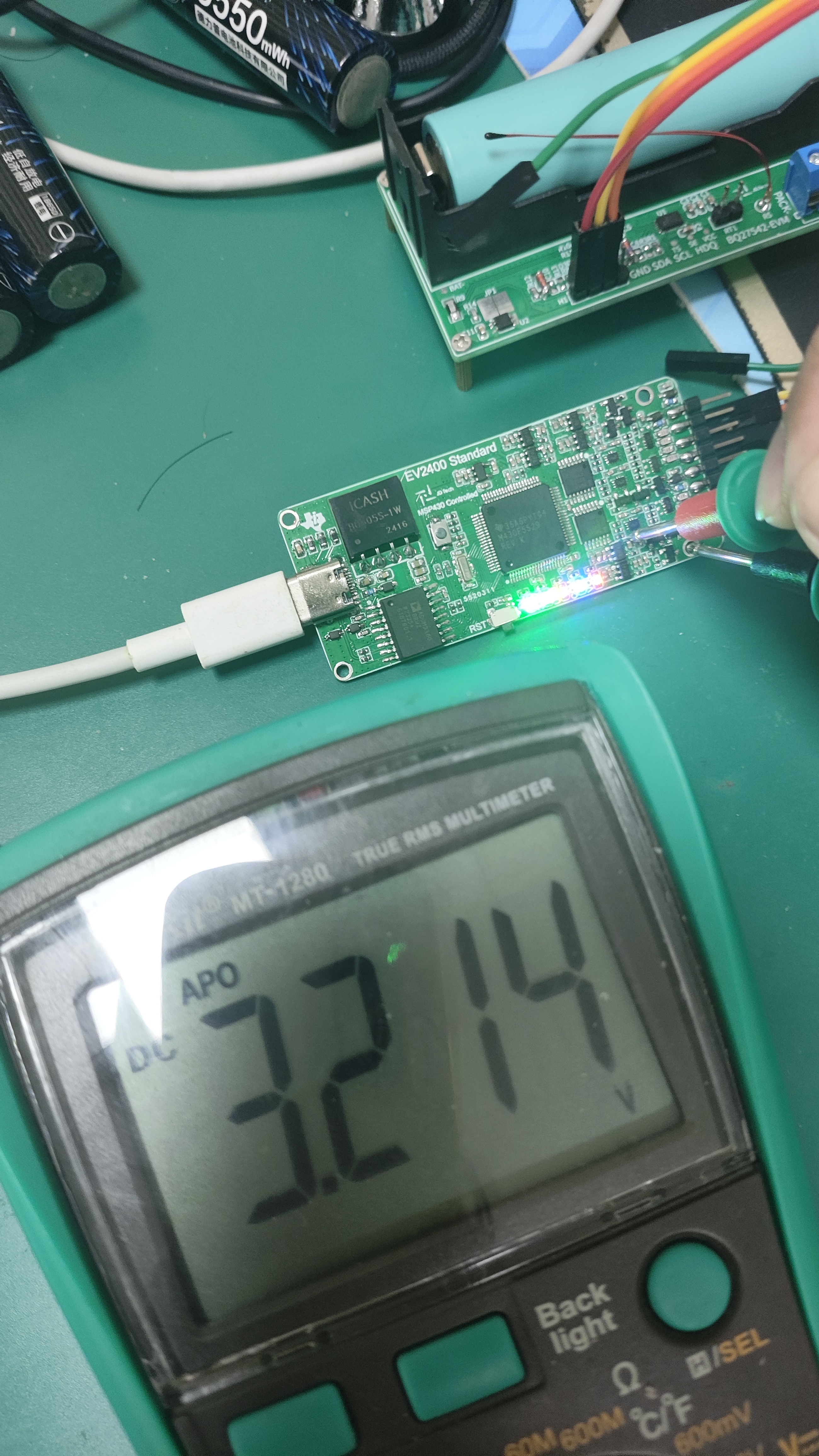
  the 3.3V power supply is mainly used as a reference level and space is limited, an LDO was used instead of a DC-DC converter to provide 3.3V.
 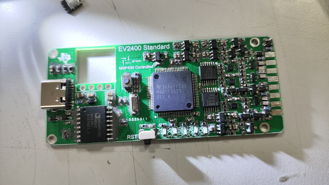 Finished product after soldering:
 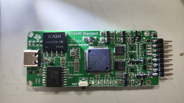 However, I still have to mention a few things about component purchasing:
 Right-click and select "Run as administrator." After installation, a "TI" folder will appear on your C drive. Locate the folder "EV2400Updater-0.32" inside. The first file in the folder is your programming program
 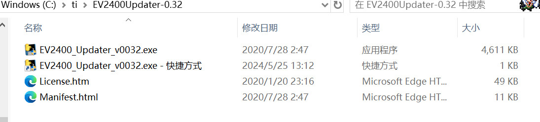 . However, if you directly open it, you'll find it says it doesn't find the EV2400. This is normal; your EV2400 hasn't been programmed yet. We need to pass parameters to this program so it knows to program a chip that doesn't have a program. Right-click the program, select "Create Shortcut," then right-click the created shortcut, click "Properties," and in the "Target" field, type a space after it, then enter "-s." Click "
 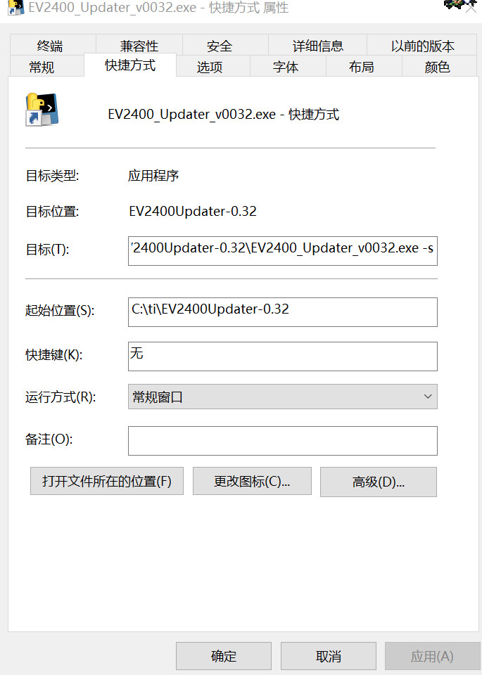 Apply" and then "OK." Now, plug your soldered EV2400 into your computer and press the button slightly to the left of the center of the board.
  Next comes the important part: While holding down the reset button, immediately release it. You should hear a device connection beep on the computer, but no new device will appear in Device Manager, indicating that the computer has recognized the chip. Double-click the shortcut you just created, and the software should indicate that it is erasing. The computer will then beep to indicate that the device has been inserted. After the software finishes running, unplug and replug the chip or press the reset button again. The computer will beep again to indicate that the device has been inserted, and the software will display the following, with all three indicator lights lit, indicating that the programming is complete. (Note: If you hold down the button for a long time, the computer will also beep to indicate that the device has been inserted and will display an unknown device. This is normal and can be ignored. Just start the process again; it is not a hardware or chip problem.)
 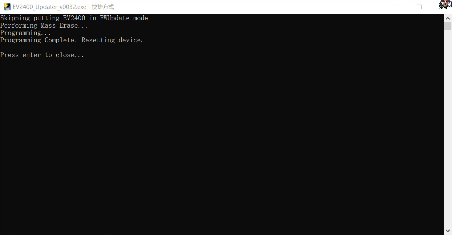 Then, go to the official website to download or download the BQStudio installation software from the attachment. After downloading and installing, insert the EV2400 with the programmed software and open BQStudio. When you open it, you will be prompted to select the target chip to debug. Select any one for now. After entering, the upper left corner will display the currently connected debugger and its software version, as shown in the figure. (If you connect the chip you want to debug before turning it on, it will be automatically recognized, no selection is needed) (The image below shows manual chip selection)
 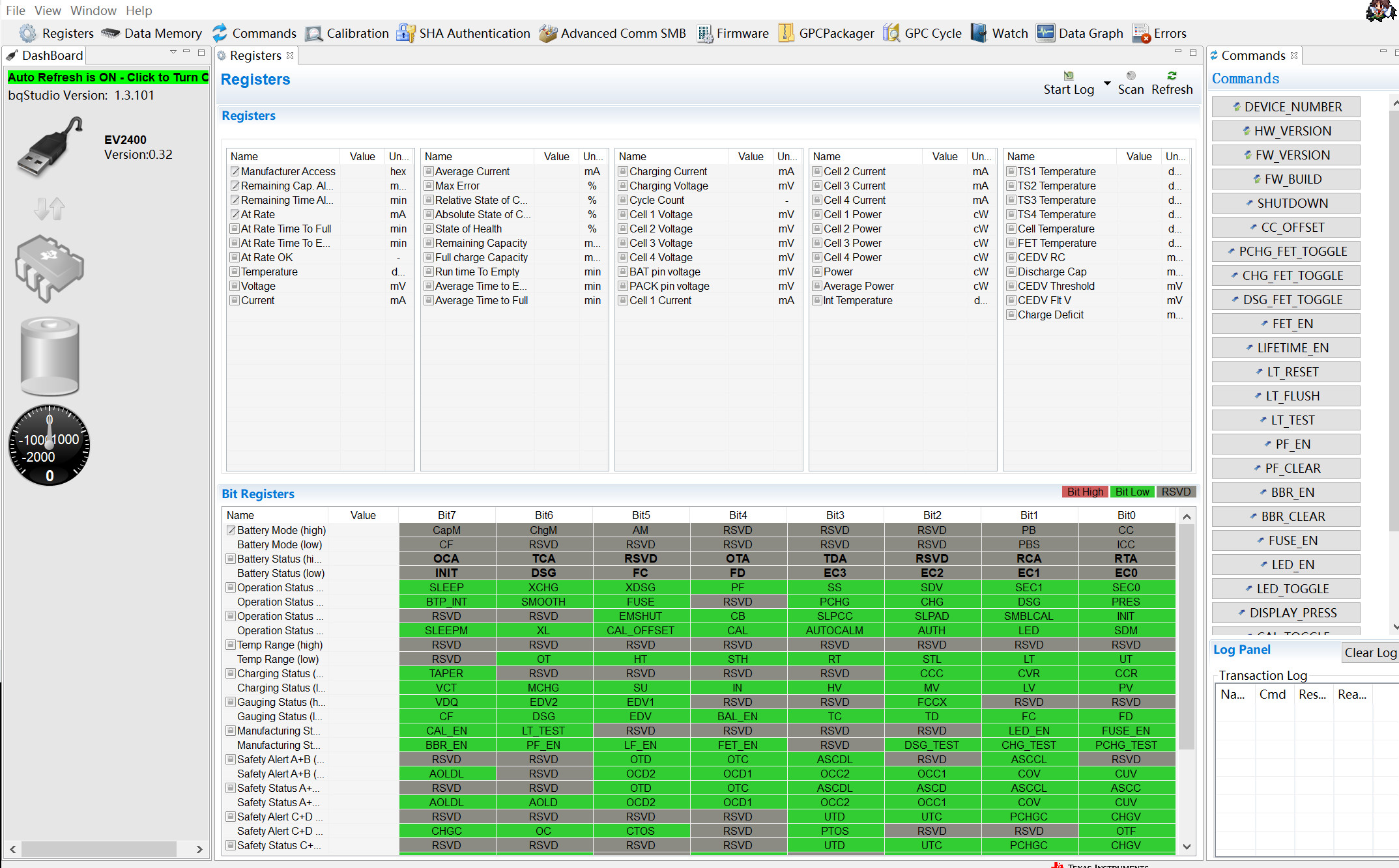 OK, at this point, the EV2400-Standard is complete. Go and enjoy the battery unlocking or the jail-like debugging!
 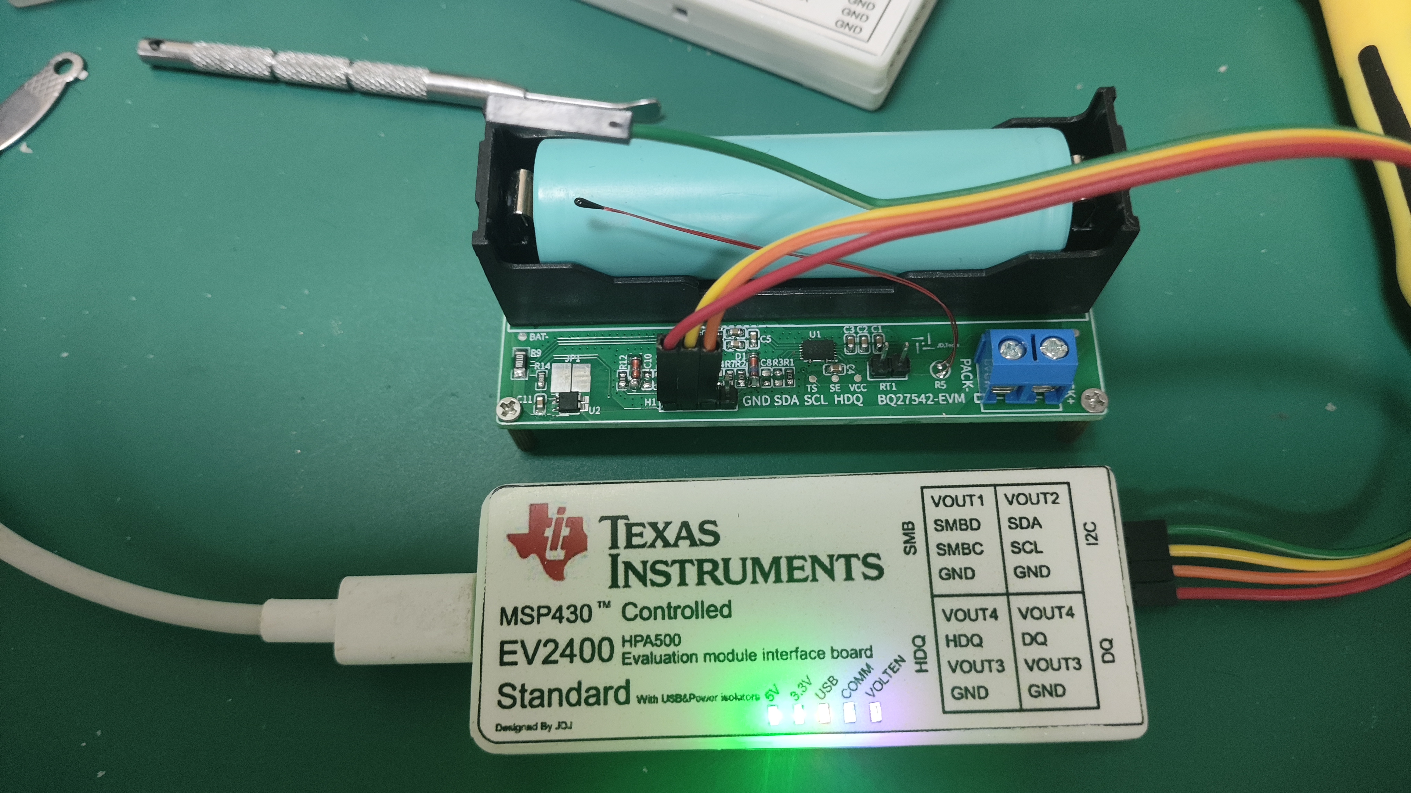 (This light is so bright, haha! A larger current-limiting resistor or a black casing would probably be better.)
All reference designs on this site are sourced from major semiconductor manufacturers or collected online for learning and research. The copyright belongs to the semiconductor manufacturer or the original author. If you believe that the reference design of this site infringes upon your relevant rights and interests, please send us a rights notice. As a neutral platform service provider, we will take measures to delete the relevant content in accordance with relevant laws after receiving the relevant notice from the rights holder. Please send relevant notifications to email: bbs_service@eeworld.com.cn.
It is your responsibility to test the circuit yourself and determine its suitability for you. EEWorld will not be liable for direct, indirect, special, incidental, consequential or punitive damages arising from any cause or anything connected to any reference design used.
Supported by EEWorld Datasheet
EEWorld
subscription
account

EEWorld
service
account

Automotive
development
community

Robot
development
community

About Us Customer Service Contact Information Datasheet Sitemap LatestNews


Room 1530, 15th Floor, Building B,
No.18 Zhongguancun Street,
Haidian District,
Beijing, Postal Code: 100190
China
Telephone: 008610 8235 0740
 京公网安备 11010802033920号

 M55342K08B110BPT1


