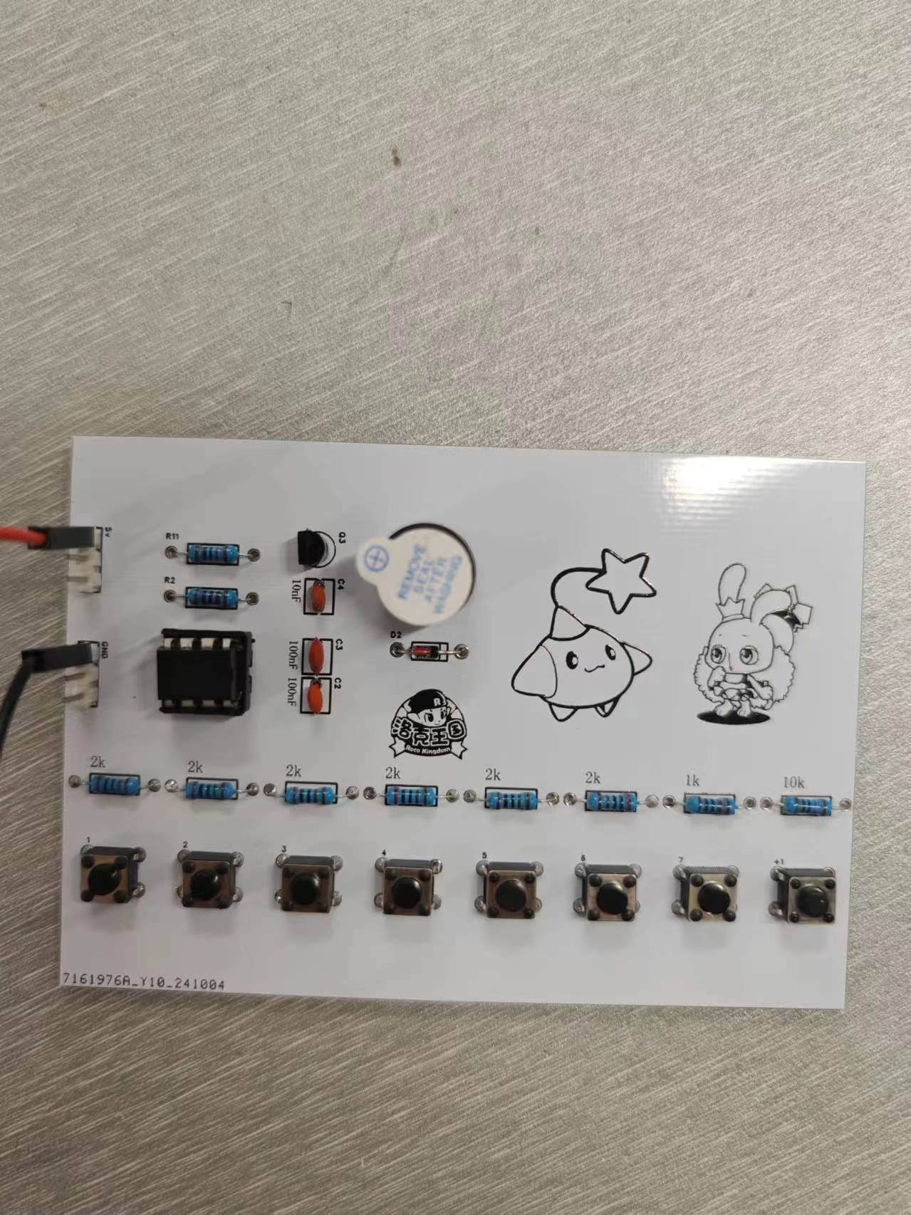
This is an eight-tone electronic keyboard based on the NE555 chip. By using the NE555 chip to emit pulses and configuring resistors of different sizes to change the frequency of the pulses, the buzzer can produce eight different pitches. It's low-cost, fun, and suitable for beginners in electronics design.
[LCSC Development Board] Design of a Novel Reader and E-book Reader Based on the Liangshan School
Using the "LCSC Liangshanpai" development board obtained from the LCSC development board website, create a GD32-based novel reader and e-book reader.
I. Project Name:
Design of a Novel Reader and E-book Reader Based on the Liangshan School of Electronic Design
II. Project Goals:
100% Open Source, Cost-Effective
Source code, PCB (this part is very basic and can be ignored), design philosophy, algorithm ideas, etc., are all open source. Of course, as I am only a sophomore and haven't learned much about analog and digital electronics, the PCB hardware part is definitely not as good as my software part, please forgive me!
Regarding the core code parts, such as: reading the dot matrix information of the font library from the TF card, the processing of GB2312 encoding and ASCII, the code for automatic line wrapping of Chinese characters on the LCD screen, the code for centering the LCD screen, the algorithm for handling file directories without quantity limit, etc., I have tried to improve its portability, that is, it can also be used in other projects in the future, thus avoiding the limitation that the code is only applicable to the Liangshan School of Electronic Design.
III. Project Objectives
Firstly, online resources for creating a novel reader using STM32 or GD32 are very limited, and even those available are mostly for ESP32. Furthermore, on Bilibili, the documentation for an STM32 novel reader project is being sold for 20 yuan. Therefore, I intend to create a 100% open-source novel reader project based on the Liangshanpai development board, hoping that the core code related to font operations, automatic line wrapping on the LCD, centering display, unlimited directory, and reading TXT files can provide some help to students!
Secondly, thank you to the LCSC development board for their project support!
Finally, "May all resources under heaven be open source!"
IV. Function Introduction
① Configure SDIO and FATFS file systems to read the dot matrix information of the font library and display the Chinese characters and other characters on the LCD screen.
② The used and unused capacity of the SD card is displayed in the UI (drawn by LCD interface functions), and the unit will automatically switch according to the SD card capacity
. ② When reading novels (TXT files), you can turn pages up and down using buttons without any garbled characters.
③ The previous code for the [LCSC Liangshan Pai Game Machine] only scanned a maximum of 100 NES directories; my version scans an unlimited number of directories and achieves unlimited novel directory reading without memory leaks—the LCSC Liangshan Pai Game Machine code can be optimized accordingly.
④ It supports inserting bookmarks and saves them as BIN files on the TF card, ensuring that bookmarks are not lost when power is off. If bookmarks exist, entering the novel will automatically jump to the bookmark page; otherwise, it will jump to the initial page.
⑤ The LCD screen brightness is adjusted via buttons; a long press of one button will adjust the brightness to the highest or lowest setting.
⑥ Font switching: The font can be switched in the settings interface. Common fonts such as [Fangsong], [Heiti], [Kaiti], [Huawen Xingkai], [Songti], [Xinsongti], and [Lishu] are provided. This is scalable and can be expanded as needed.
⑦ Regarding the image logo, I used the logo from the LCSC Liangshanpai game machine, but the usage is quite different. The Liangshanpai game machine logo is stored in the microcontroller's Flash memory by taking a mold, which takes a long time each time the code is burned, making it inconvenient. Therefore, I ran code on the microcontroller to create a BIN file from the image mold data and save it in the TF card via the file system, greatly saving burning time.
⑧ Serial port synchronous printing of operation information.
V. Skills Acquisition
① What I Learned:
First, through this novel reader project, I became more proficient in using the file system, further improved my ability to write multi-level menus, and became more skilled in handling GB2312 and ASCII encodings. In the future, if I encounter a part where I need to display Chinese characters on an LCD screen, I can easily solve it through the file system. Regarding the C language, I made unprecedented progress. For example, the code involved a lot of use of pointers, structure arrays, structures, and dynamic memory allocation and deallocation. I had rarely used these aspects of C language before, but I had a lot of application in this project, allowing me to appreciate the convenience of these data types.
Secondly, PWM adjusts the LCD screen brightness; the state machine detects buttons and recognizes long and short presses; the CubeMx configuration file system is used; combined with the file system and font library, the font dot matrix information is read from the TF card; TXT text is read from the file system and displayed on the LCD screen; infinite scanning of the file directory is supported.
② Shortcomings:
There are many regrets regarding the PCB design. My current situation is that my hardware design capabilities cannot support my software design capabilities, which means that some functions I originally wanted to add had to be cut due to insufficient hardware capabilities. Therefore, I hope to make up for the hardware limitations in the future.
VI. Problems Encountered and Solutions
① Regarding the problem of TF card initialization failure caused by the automatically generated code when configuring SDIO using STM32CubeMx
: SDIO initialization should be initialized with one data line, but the code generated by CubeMx initializes it with four data lines, which seems to be a CubeMx bug.
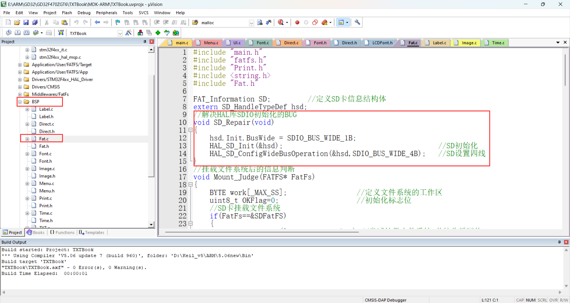
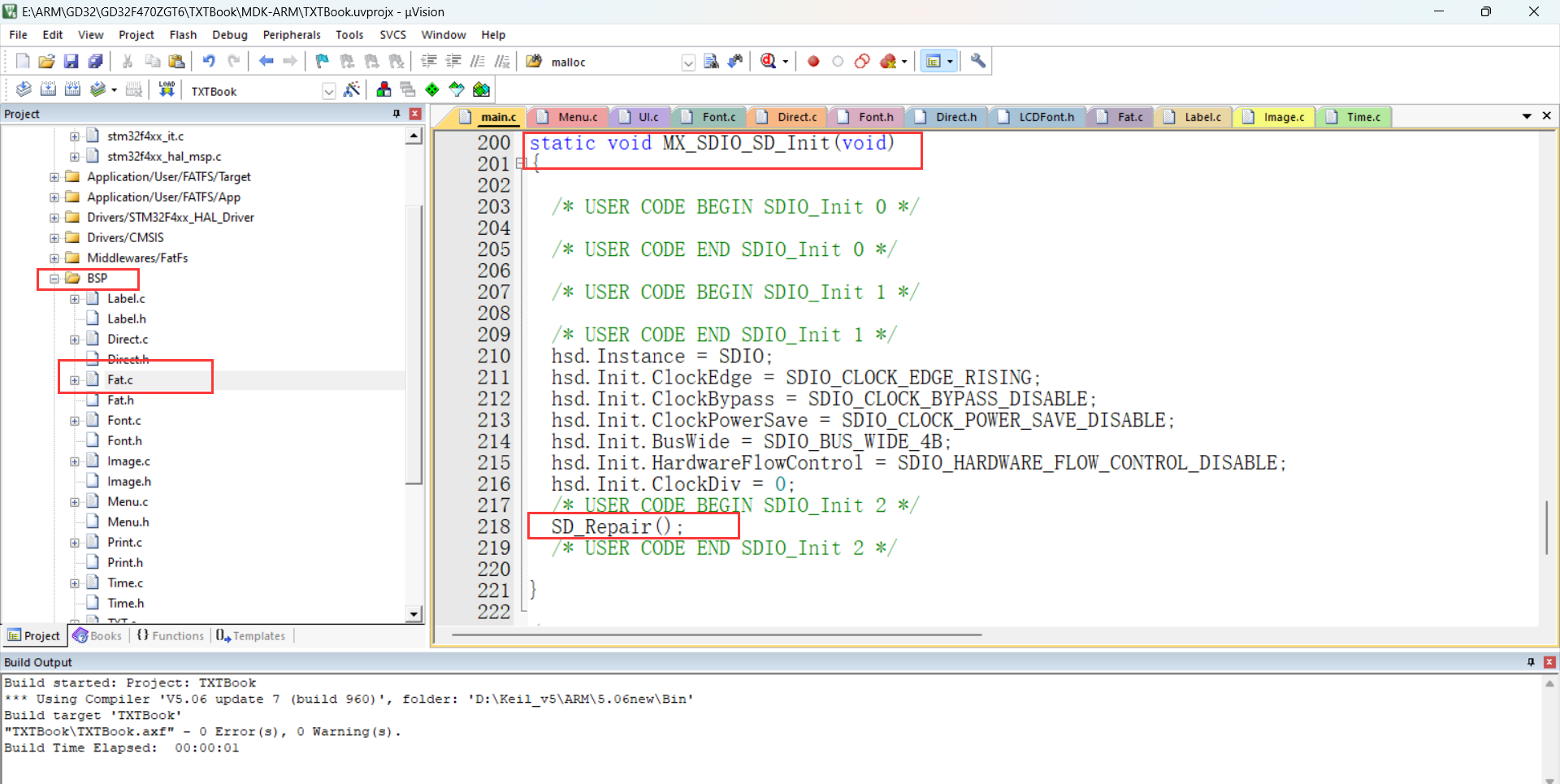
Here, I encapsulated an SDIO initialization repair function to initialize SDIO with one data line and then change the data line to four to solve this problem.
② Regarding the selection and processing of font encoding, how to display Chinese characters using the font library?
I created three font sizes: 16*16, 24*24, and 32*32.
One 16*16 Chinese character = 16*16/8 = 32 bytes;
one 24*124 Chinese character = 24*24/8 = 72 bytes;
one 32*32 Chinese character = 32*32/8 = 128
bytes. I also created seven fonts: 【仿宋】, 【黑体】, 【楷体】, 【华文行楷】, 【宋体】, 【新宋体】, and 【隶书】.
Website: GB2312 Encoding Table - Hammer Online Tools (toolhelper.cn)
Website: ASCII Code - Basic ASCII Code and Extended ASCII Code, the most complete Chinese ASCII code comparison table 0~255 (asciim.cn)
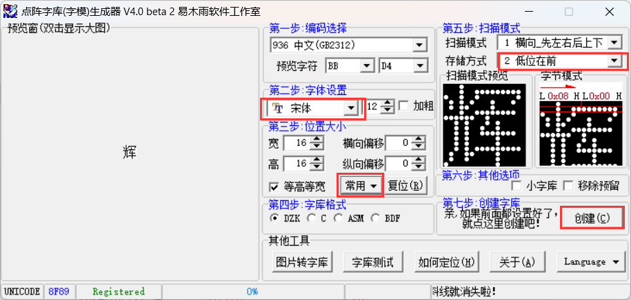
Here I've chosen the GB2312 encoding format. First, it's important to understand the GB2312 encoding format. GB2312 is a Chinese character encoding. In the GB2312 character set, both Chinese and English characters occupy two bytes. The first byte ranges from [0xA1, 0xF7], and the second byte ranges from [0xA0, 0xFF].
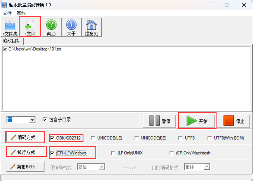
Novels or TXT files must be in GB2312 encoding format; otherwise, garbled characters will appear. This can be done using an encoding conversion tool
. ③ How to achieve mixed Chinese and English display?
Most screen driver code provided by screen manufacturers displays Chinese and English separately, and cannot display both simultaneously through a single function, making it very inconvenient to use. What I want to achieve is to display it on the LCD screen, similar to how `printf("你好世界Hello")` is printed on a computer. Before that, we need to analyze the string "你好世界Hello". This string contains four Chinese characters and six English characters. In the code, the Chinese characters are in GB2312 encoding format, while the English characters are in ASCII format. Chinese characters can be addressed based on their encoding, while English letters need to be converted to their corresponding English character encoding in GB2312. ASCII characters 32 to 126 correspond to GB2312 characters 0xA30xA0 to 0xA30xFE. Therefore, the offset calculation formula can be derived: addr = ((0xa3-0xa1)*94 + (uint8_t)*gbk + 128 - 0xa1)*Font.ByteSize; (Font.ByteSize is the size of a GB2312 encoded character in bytes; font size 16 occupies 32 bytes, font size 24 occupies 72 bytes, and font size 32 occupies 128 bytes; *gbk is the ASCII encoding corresponding to the English character). Finally, the dot matrix information is read into the cache through the file system and displayed on the screen using the LCD's underlying display functions.
④ Since the TXT file contains both GB2312 encoded Chinese characters and ASCII English characters, how should this be handled to avoid garbled characters?
Design philosophy: Since we cannot predict where the file system will read a complete character, if we read a fixed number of bytes each time, and happen to read the first byte of a Chinese character, which happens to meet the byte count requirement, the Chinese character encoding will be truncated, resulting in garbled characters in the subsequent parts. My idea is: the screen size is fixed, and there are curved parts around the screen, so I use partial display of characters, 13 * 15 = 195 characters, that is: display 195 characters at a time. Assuming that all 195 characters read are GB2312 encoded Chinese characters, then it will be at most 390 bytes. Inevitably, there will be some characters that occupy bytes but cannot be displayed, such as the newline character: CR+LF (occupying two bytes). We need to ignore these non-displayable characters, so to be on the safe side, we read 500 bytes after that. After each character is displayed, we increment by one. At the same time, we count the number of bytes according to whether it is GB2312 encoding or ASCII encoding, return the counted bytes and accumulate them, and use the accumulated result as the starting byte for the next reading. The above describes the backward reading method. The forward reading method is similar: read 500 bytes backward from the current position and count them. When exactly 195 characters have been read, return the number of bytes. Then, offset the current position forward by the returned byte count. Next, from the offset position, read the returned byte count backward and display it on the LCD screen. However, it's crucial to note that if the current byte count is less than 500 bytes from the beginning of the file, the position must be offset from the beginning of the file.
⑤ How to implement the novel bookmark insertion function?
Initially, I planned to use AT24C or W25Q, but these storage chips have relatively small capacities, and separating the ebook and bookmarks would be very inconvenient for management. Therefore, I continued to use the file system to create BIN files to store bookmarks; each bookmark is eight bytes, four for storing the page number and four for storing the byte offset position. Regarding the bookmark design, when entering and reading a novel, the system first checks for bookmarks. If a bookmark exists, it jumps to the bookmark page, and the page number turns red. If no bookmark exists, it jumps to the beginning of the novel. To insert a bookmark, long-press the confirmation button. After successful insertion, the page number turns red.
⑥ How to implement font switching?
A font library is defined using a structure. The structure stores important information such as font size, font library location, and the number of bytes occupied by a character. Modifying the font means re-initializing the font library information, which is equivalent to modifying the font library's location information.
VI. Project Declaration:
This project is primarily open-source in terms of software!
You can port the code of this project to your own projects. However, I am not responsible for any consequences arising from its use in your own projects!
PDF_【LCSC Development Board】Design of a Novel Reader and E-book Reader Based on the Liangshan School.zip
Altium_【LCSC Development Board】Design of a Novel Reader and E-book Reader Based on the Liangshan School.zip
PADS_【LCSC Development Board】Design of a Novel Reader and E-book Reader Based on the Liangshan School.zip
BOM_【LCSC Development Board】Design of a Novel Reader and E-book Reader Based on the Liangshan School.xlsx
The breadboard is powered by 5V and 3.3V.
Powered by a tiny breadboard, it can be used as long as you have a Type-C port at home.
Used for breadboard power supply, providing one 5V and one 3.3V output; the LDO used is an RT9013.
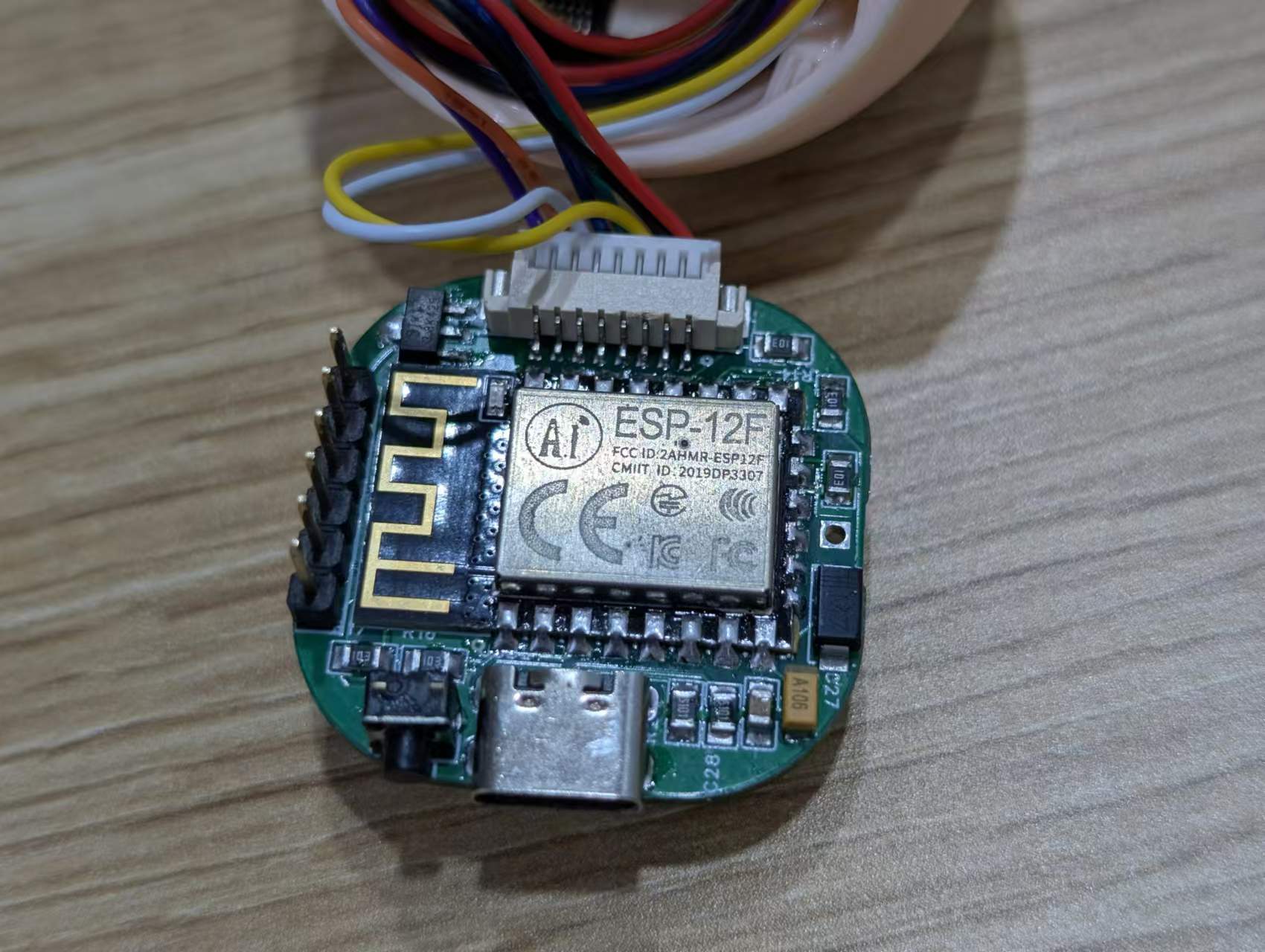
This project is based on the ESP8266 and uses easily solderable components such as the 0805, making it suitable for teaching.
Project Overview:
This project is based on the ESP8266 and is a simple information display device for desktop placement. It uses components in larger packages such as 0805, which are easy to solder and convenient for teaching. The
project cost is approximately 25 yuan, with the major expenses being the screen and main controller. The screen costs approximately 10 yuan, and the main controller costs approximately 4 yuan.
Project Functionality:
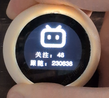
This project is a desktop mini-TV project based on the ESP8266, used to display emoticons, clock, weather, and Bilibili personal information. Users can switch interfaces using buttons, and long-pressing a button in the emoticon interface allows switching emoticons.
✅Emoji Display
✅Clock Display
✅Daily Weather
✅Bilibili Information
Project Parameters
This design uses an ESP8266 main controller with built-in WIFI to complete network requests;
it uses an ST7789 0.96-inch circular LCD display to show emojis, clock, weather, Bilibili information, etc.;
an AMS1117 LDO linear regulator is used to convert 5V to 3.3V to power the main controller;
the Type-C interface has a 5.1K resistor and supports dual Type-C cable power input;
Development Documentation
Online Documentation:
JLCPCB EDA Wiki
Offline Documentation:
Please see the attachment 【TV-Lite Small TV Development Documentation.pdf】
Principle Analysis (Hardware Description)
The circuit of this project consists of the following parts: power supply section, ESP8266 main controller, and external interface
power circuit:
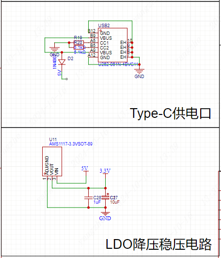
Power Supply Interface: Uses a TYPE-C-6P interface with large pads for easy soldering. 5.1K pull-down resistors are added to the CC1 and CC2 pins for easy identification and configuration by different hosts, supporting dual Type-C cable power supply. A diode is added at the 5V power supply input to prevent reverse voltage from the battery from damaging the Type-C port's power supply.
Voltage regulator: An AMS1117 linear regulator is used to convert the 5V voltage to 3.3V, providing power to the ESP8266 main controller and LCD screen.
Main controller circuit:

Referencing the ESP8266 datasheet, pull-up pins IO0, IO2, EN enable, and RST reset are configured, while the CS chip select signal is pulled down to ensure normal ESP8266 and SPI communication.
External interface circuit:

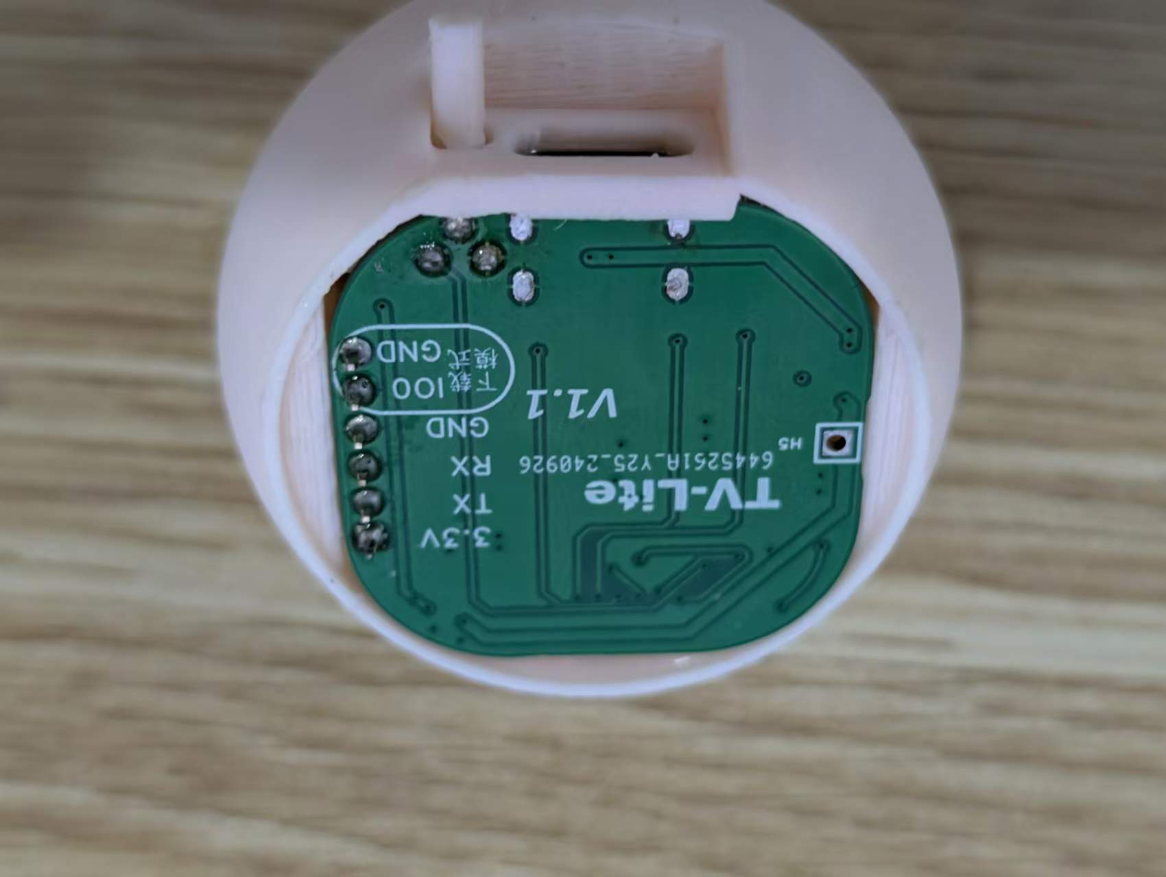
Screen: Due to space limitations and for ease of replication, a 0.96-inch ST7789 LCD module is used. This module has its own screen driver circuit; only interface connection is required. The corresponding interface pinout is configured according to the screen module's pinout; it can be used directly upon insertion.
Serial port: For convenient downloading, the serial port has a separate IO0 and GND interface as a jumper insertion interface. When a jumper is inserted, IO0 is pulled low, entering download mode. Conversely, the main control circuit pulls the voltage high, entering the working mode.
Battery: The battery section has a 5V circuit. Due to layout limitations, users who wish to use battery power can purchase and connect a charge/discharge module.
Buttons: The buttons use the IO2 pin; the button is pulled low when pressed and pulled high when idle. The complete project file
with the software code
is attached, along with the directly programmable binary and file system binary files, which can be downloaded.
Due to time constraints, the program still contains some redundant and low-level code logic. There are many areas where resource consumption can be optimized.
The network configuration code can be modified.
`void handleWiFiConfig() {
server.on("/", HTTP_GET, [](AsyncWebServerRequest *request) {
if(SPIFFS.exists("/index.html")) {
fs::File file = SPIFFS.open("/index.html", "r");//Read from the FS file system
if(file) {
size_t fileSize = file.size();
String fileContent;
while(file.available()) {
fileContent += (char)file.read();
}
file.close();
request->send(200, "text/html", fileContent);
return;
}
}
request->send(404, "text/plain", "File Not Found");
});
server.on("/connect", HTTP_POST, [](AsyncWebServerRequest *request) {//Web service receives
String ssid =` request->getParam("ssid", true)->value();
String pass = request->getParam("pass", true)->value();
String uid = request->getParam("uid", true)->value();
String city = request->getParam("city", true)->value();
String api = request->getParam("api",`true)->value();
// Save WiFi information to file
DynamicJsonDocument doc(1024);
doc["ssid"] = ssid;`
In the program, the ESP8266 reads an HTML webpage from
the FS file system and
mounts it to its local network port. Users can then access the HTML network configuration page via 192.168.4.1 by connecting to the hotspot. The user -submitted form is returned to the ESP8266 via a POST request . To prevent users from repeating the same steps after a reboot, the form information needs to be saved in JSON format to the FS file system for direct reading upon the next boot, thus avoiding repetitive and tedious network configuration operations. Then, simply enter the WiFi name and password in the WiFi.begin method to connect to the WiFi network. HTML code for the webpage : <div> <h1>TV-Lite Control Center</h1> <p>This project is based on the ESP8266 main controller</p> <input type="text" name="ssid" /> <input type="password" name="pass" /> <input type="uid" name="uid" /> <input type="api" name="api" /> <input type="city" name="city" /> <input type="submit" style="height:50px;width:320px" value="Save" /> <a href="https://lceda.cn/"> <table style="height:200px"> <tr> <th>Device Name:</th> <td>TV-Lite</td> </tr> <tr> <th>Memory Size:</th> <td>4MB</td> </tr> <tr> <th>Console Version:</th> <td>V1.1</td> </tr> <tr> <th>Official Website:</th> <td> <a href="https://lceda.cn/">LCSC EDA</a></td> </tr> </table> </a> </div> Create a new folder named "data" in the project directory, create a file named "index.html", and write the HTML code for the network configuration webpage. In this code, a form is created, containing input boxes for WiFi name, password, bilibili user ID, Xinzhi Weather API, and city weather (lowercase). After the user clicks "submit", the information is securely passed to the program via the POST method, and the program reads the information from the "name" field in the input box. FLASH read/write storage code void loadWiFiConfig() { if (SPIFFS.begin()) { fs::File file = SPIFFS.open(ssidFile, "r"); if (file) { DynamicJsonDocument doc(1024); DeserializationError error = deserializeJson(doc, file); if (!error) { String ssid = doc["ssid"]; String pass = doc["pass"]; String uid = doc["uid"];
String city = doc["city"];
String api = doc["api"];
useruid=uid;
cityname=city;
weatherapi=api;
WiFi.begin(ssid.c_str(), pass.c_str());
// Attempt to connect to WiFi, wait up to 10 seconds
unsigned long startAttemptTime = millis();
while (WiFi.status() != WL_CONNECTED && millis() - startAttemptTime < 5000) {
delay(500);
}
// If the connection fails, print the status
if (WiFi.status() != WL_CONNECTED) {
Serial.println("WiFi connection failed, starting captive portal...");
startCaptivePortal();
} else {
Serial.println("WiFi connected");
timeClient.begin();
}
}
file.close();
}
}
Previously
, we mentioned how to configure the network via Wi-Fi and save the data to the FS file system in JSON format. Therefore, reading the configuration information here is relatively easy. Simply read the JSON data and then follow the steps to start the Wi-Fi connection.
Screen Wiring Settings
: #define USER_SETUP_INFO "User_Setup"
#define ST7789_DRIVER // Full configuration option, define additional parameters below for this display
#define TFT_RGB_ORDER TFT_BGR // Colour order Blue-Green-Red
#define TFT_WIDTH 240 // ST7789 240 x 240 and 240 x 320
#define TFT_HEIGHT 198
#define TFT_BL 4 // LED back-light control pin
#define TFT_BACKLIGHT_ON HIGH // Level to turn ON back-light (HIGH or LOW)
#define TFT_MOSI 13
#define TFT_SCLK 14
#define TFT_CS 15 // Chip select control pin
#define TFT_DC 5 // Data Command control pin
#define TFT_RST -1 // Set TFT_RST to -1 if display RESET is connected to ESP32 board RST
#define LOAD_GLCD // Font 1. Original Adafruit 8 pixel font needs ~1820 bytes in FLASH
#define LOAD_FONT2 // Font 2. Small 16 pixel high font, needs ~3534 bytes in FLASH, 96 characters
#define LOAD_FONT4 // Font 4. Medium 26 pixel high font, needs ~5848 bytes in FLASH, 96 characters
#define LOAD_FONT6 // Font 6. Large 48 pixel font, needs ~2666 bytes in FLASH, only characters 1234567890:-.apm
#define LOAD_FONT7 // Font 7. 7 segment 48 pixel font, needs ~2438 bytes in FLASH, only characters 1234567890:-.
#define LOAD_FONT8 // Font 8. Large 75 pixel font needs ~3256 bytes in FLASH, only characters 1234567890:-.
#define LOAD_GFXFF // FreeFonts. fonts
#define SMOOTH_FONT
#define SPI_FREQUENCY 40000000
#define SPI_READ_FREQUENCY 20000000
#define SPI_TOUCH_FREQUENCY 2500000
#define USE_HSPI_PORT
For ease of use, the screen uses the TFT-eSPI library, configured as shown in User_Setup.h. However, since we are using a non-circular screen, some driver-level methods need to be modified.
The screen display definition
is added to ST7789_Defines.h with a 198x240 screen display definition.
//0.96 circle TFT support
#if (TFT_HEIGHT == 198) && (TFT_WIDTH == 240)
#ifndef CGRAM_OFFSET
#define CGRAM_OFFSET
#endif
#endif
The screen rotation definition is added
to ST7789_Rotation.h. Under
case 2:, add
else if(_init_height == 198)
{
colstart = 0;
rowstart = 122;
}
Under case 3:, add
else if(_init_height == 198)
{
colstart = 122;
rowstart = 0;
}
Key code
void IRAM_ATTR handleButtonPress() {
unsigned long currentTime = millis();
if (digitalRead(buttonPin) == LOW && !buttonPressed) { // Detect button press and not recorded as pressed
buttonPressed = true;
pressStartTime = currentTime; // Record the time when pressed
}
// Detect if it is a long press
if (buttonPressed && (currentTime - pressStartTime) > LONG_PRESS_DELAY) {
isLongPress = true;
}
// Detect if button is released
if (digitalRead(buttonPin) == HIGH && buttonPressed) {
if (isLongPress) { // If it is a long press
if (currentPage == 0) { // Only switch emojis on the first page
emojiState = (emojiState + 1) % 8; // The code snippet
`mylcd.fillScreen(TFT_BLACK); // Clear screen
}
} else { // If it's a short press
if (currentTime - lastDebounceTime > debounceDelay) {
currentPage = (currentPage + 1) % 4; // Short press to switch pages
lastDebounceTime = currentTime;
mylcd.fillScreen(TFT_BLACK); // Clear screen
}
}
// Reset button state
buttonPressed = false;
isLongPress = false;
}
mylcd.fillScreen(TFT_BLACK); // Clear screen
}`
demonstrates how to ensure an immediate response when a button is pressed. This interrupt operation ensures that the program immediately performs the page-turning operation when a button is pressed, without waiting for the current page's program to finish executing, thus providing a fast response.
Since the logic for switching emojis involves a long press on the emoji page, a timer is needed to monitor the duration of the button press to determine whether it's a long press or a short press. An `if` statement is used to determine if the long press occurred on the emoji page and not another page.
Finally, a full-screen black screen needs to be added to refresh the screen, ensuring that the content of the previous page is cleared before the next page.
Page function code
void bilibili() {
if (initbilibili==false) {
mylcd.fillScreen(TFT_BLACK);
if (WiFi.status() == WL_CONNECTED) {
WiFiClientSecure client;
client.setInsecure();
HTTPClient http;
if (http.begin(client,bilibiliAPI+useruid)) {
int httpCode = http.GET();
if (httpCode > 0) {
String payload = http.getString();
Serial.println("JSON Response:");
Serial.println(payload);
DynamicJsonDocument doc(1024);
deserializeJson(doc, payload);
String following2 = doc["data"]["following"];
// Accessing data key
String follower2 = doc ["data"]["follower"]; following
=following2; follower
=follower2 ;
initbilibili = true ; http.end(); } else { Serial.println("Failed to connect to server"); } mylcd.fillScreen(TFT_BLACK); } mylcd.pushImage(mylcd.width() / 2-(99/2), 10, 99, 99,bilibiliimg); mylcd.pushImage(50, 125, 25, 25,guan); mylcd.pushImage(80, mylcd.pushImage ( 60 , 160, 25, 25,sui); mylcd.pushImage(90, 160, 25, 25, maohao); mylcd.drawString(follower, 120, 160, 4); } } This code snippet uses the functional code from the BiliBili page. First, it clears the screen to ensure the previous page's content is erased. Then, it checks the network connection. If the connection is successful, it starts HTTPClient, sends a GET request to the online server, receives the returned JSON value, parses it, and stores it. Then, it closes the HTTP request and executes the screen display code. Because images are used in the screen display, it first uses `mylcd.pushImage` to output the `bilibiliimg` image from `image.cpp` (included in the header file) to the upper center of the screen. It then uses `mylcd.width()` to get the screen width divided by 2, and then subtracts the image width divided by 2. Similarly, it outputs the image and text sequentially, and then uses `mylcd.drawString` to output the String type text (of course, other formats can also be used; refer to the previously stored value format for details). Finally, let's explain why `initbilibili == false` was used at the beginning. This is to ensure that the page's program executes only once, avoiding screen flickering and allowing for faster program response, essentially converting a dynamic page into a static one. The UI logic code is as follows: `switch (currentPage) { case 0: // Homepage initbilibili = false; switch (emojiState) { case 0: mylcd.pushImage(mylcd.width() / 2-(200/2), mylcd.height()/2-(100/2), 200, 100,hi); // Emoji 1 break; case 1: }`
mylcd.pushImage(mylcd.width() / 2-(200/2), mylcd.height()/2-(100/2), 200, 100,nice);// Expression 2
break;
case 2:
mylcd.pushImage(mylcd.width() / 2-(200/2), mylcd.height()/2-(100/2), 200, 100,mid);//expression 3
break;
case 3:
mylcd.pushImage(mylcd.width() / 2-(200/2), mylcd.height()/2-(100/2), 200, 100,unhappy);
break;
case 4:
mylcd.pushImage(mylcd.width() / 2-(200/2), mylcd.height()/2-(100/2), 200, 100,error);
break;
case 5:
mylcd.pushImage(mylcd.width() / 2-(200/2), mylcd.height()/2-(100/2), 200, 100,star);
break;
case 6:
mylcd.pushImage(mylcd.width() / 2-(200/2), mylcd.height()/2-(100/2), 200, 100,love);
break;
case 7:
mylcd.pushImage(mylcd.width() / 2-(200/2), mylcd.height()/2-(100/2), 200, 100,what);
break;
case 8:
mylcd.pushImage(mylcd.width() / 2-(200/2), mylcd.height()/2-(100/2), 200, 100,dowhat);
break;
}
break;
case 1: // Second page
if (WiFi.status() != WL_CONNECTED) {
Serial.println("Starting captive portal...");
mylcd.pushImage(mylcd.width() / 2-(99/2), 10, 99, 99,wifi);
mylcd.drawString("WIFI:TV-Lite", 50, 125, 4);
mylcd.drawString("IP:192.168.4.1", 40, 155, 4);
}else {
showClockPage(); // Display clock
}
break;
case 2: // Third page
if (WiFi.status() != WL_CONNECTED) {
Serial.println("Starting captive portal...");
mylcd.pushImage(mylcd.width() / 2-(99/2), 10, 99, 99,wifi);
mylcd.drawString("WIFI:TV-Lite", 50, 125, 4);
mylcd.drawString("IP:192.168.4.1", 40, 155, 4);
}else {
initialized = false;
fetchWeather(); // Get the weather
}
break;
case 3: // Fourth page
if (WiFi.status() != WL_CONNECTED) {
Serial.println("Starting captive portal...");
mylcd.pushImage(mylcd.width() / 2-(99/2), 10, 99, 99,wifi);
`mylcd.drawString("WIFI:TV-Lite", 50, 125, 4);
mylcd.drawString("IP:192.168.4.1", 40, 155, 4);
}else {
initweather = false;
bilibili(); // Display the bilibili page
}
break;
}`
The page logic is relatively simple, using a switch statement to determine the page number.
Additionally, to ensure no issues arise when the user is offline, a WIFI status check is added, prompting the user to configure the network when online functions are offline.
Finally, `initxxx = false;` needs to be added at the end of each page to ensure that the page's functionality is initialized upon the next page entry.
Panel Design:
There are two types of 0.96-inch circular LCD displays on the market: one with a glass cover and one without. For users who prefer customization, a suitable personalized panel template is provided, which can be customized through LCSC Panel Maker.
3D Shell Design:
This project is compatible with a corresponding circular FDM printed shell. The shell has a fixing slot for easy mounting of the circuit board. The cover is secured primarily by the friction of the layer textures. The shell has been verified on an FDM 3D printer.
Precautions:
Ensure the power supply voltage is 5V. Do not use other voltage values.
Device configuration address: 192.168.4.1. Please connect to the Wi-Fi network first, then access this address.
The weather API used is the Xinzhi Weather API, which is a free API. Please register on the official website to obtain the API key and enter it into the configuration address. The
clock interface may be out of sync upon initial startup; please wait a moment. Assembly Process:
The assembly process is relatively simple, requiring only a motherboard, a connecting cable, a screen, and a shell.
First, connect one end of the connecting cable to the screen.
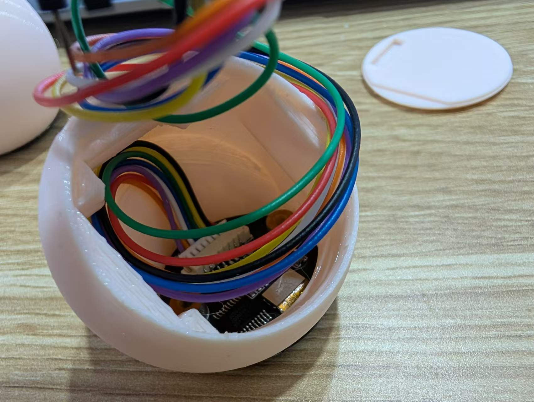
Second, thread the cable through the shell and secure the screen with glue.
Finally, insert the cable into the shell, insert the motherboard into the limiting slot, and then close the bottom cover according to the opening.
Image
1:
Emoji Page;

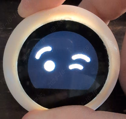
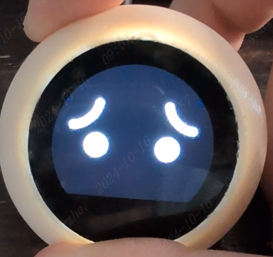
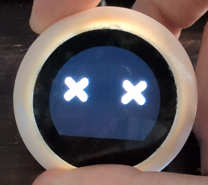
Image 2: Clock Page;
Image 3: Weather Page;


Image 4: Bilibili Page.
Attachment Description :
【TV-Lite.zip】: Program Source Code;
【firmware.bin】: Program Firmware;
【spiffs.bin】: FS File System Firmware;
【TV-Lite.SLDASM】: Combined File;
【TV-Lite.SLDPRT】: Shell Source File;
【TV-Lite_Bottom.SLDPRT】: Bottom Shell Source File ;
【TV-Lite_KEY.SLDPRT】: Button Growth Source File;
【TV-Lite.stl】: Shell 3D File; 【TV-
Lite_Bottom.stl】: Bottom Shell 3D File;
【TV-Lite_KEY.stl】: Button Growth 3D File.
Notes : For the 3D shell, it is recommended to use an FDM printer. For the OLED display, a 0.96-inch round screen
is recommended. For the buttons, it is recommended to purchase 2.5x2.5x10mm, which does not require growth.
The PCB card is drawn based on the campus map of Fudan University's Handan campus. It includes NFC functionality and requires the soldering of three components. It can also be used as a decorative item without soldering any components.
This project describes
a PCB card based on a map of Fudan University's Handan campus. It includes NFC functionality and requires the soldering of three components. It can also be used as a decorative item without soldering any components. The project files include a standard silkscreen version (free PCB fabrication available, but immersion gold plating costs extra) and a color silkscreen version (50 RMB including immersion gold plating). Please choose according to your budget.
Finished Product Showcase
: 3D Preview Images:
Standard Silkscreen Version

: Color Silkscreen Version:

Physical Display
(Unsoldered Version, Free Tin Plating):
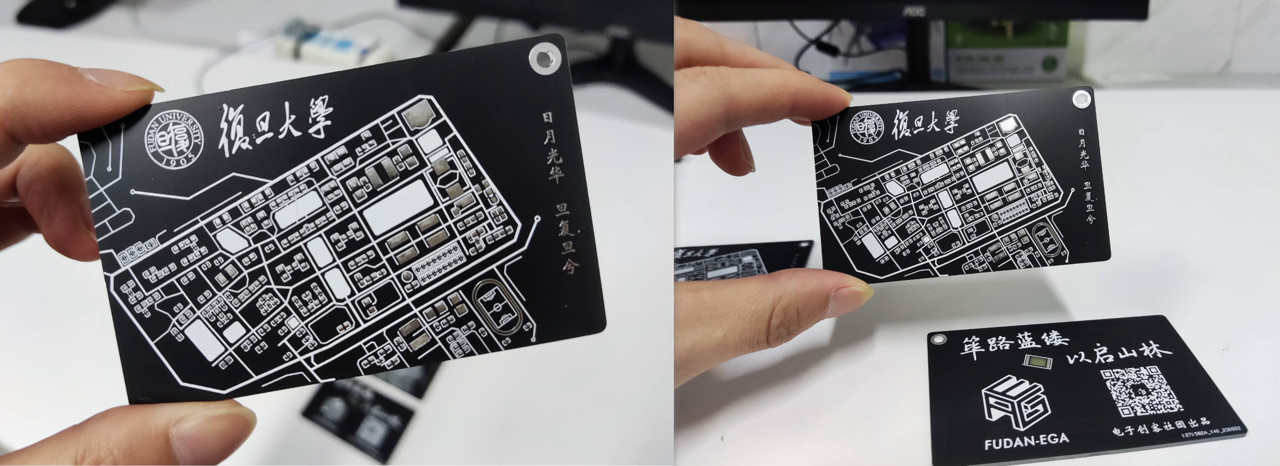
Immersion Gold Plating Physical Display:

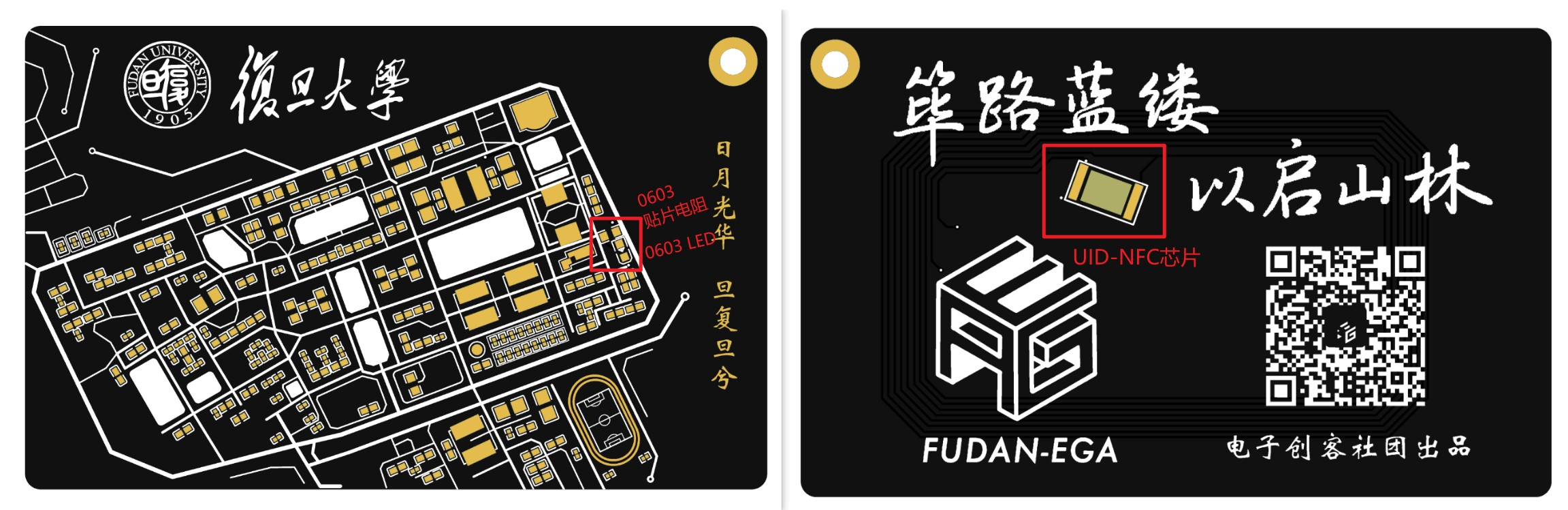
NFC Functionality Description :
To achieve NFC functionality and a lighting effect, three components need to be soldered: a COB-UID chip (available online), a 0603 surface mount resistor (around 1kΩ), and a 0603 LED. The soldering positions are shown in the image below.
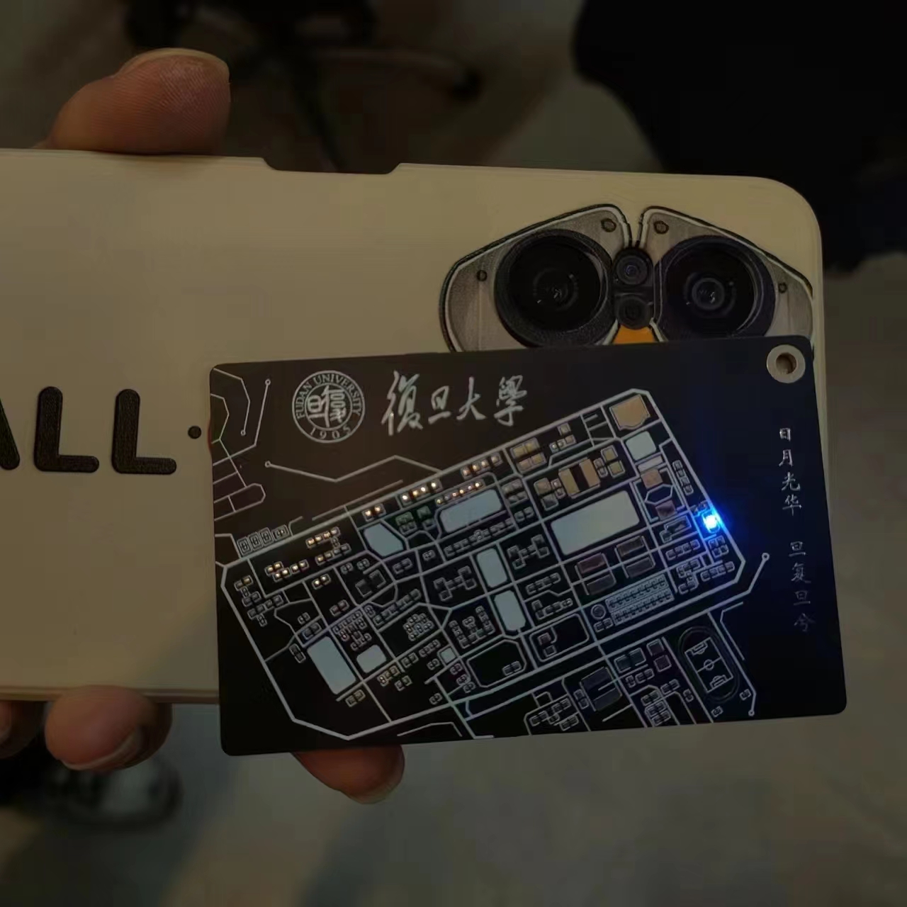
Using the purchased UID chip as an empty card, a simple access card function can be implemented using an NFC reader/writer module. Other functions can be explored independently. The final lighting effect is shown in the image below. The video at the end of the article also demonstrates its function as a campus card replacement.
Free ordering process
: The ordering tutorial has been published on our official WeChat account: https://mp.weixin.qq.com/s/83xuf8kCBW1OrjdyY2VXUA
Design Team: Fudan University Electronic Makers Club
The Fudan University Electronic Makers Club (hereinafter referred to as "Electronic Makers Club") was founded in 2015, dedicated to creating a university-wide platform for sharing scientific and technological innovations and exploring the application prospects of intelligent hardware.
Many members of the club have participated in various competitions such as electronic design competitions, optoelectronic design competitions, and the China-US Youth Maker Competition, possessing rich experience in participation and awards. The club can provide students with abundant hardware sharing resources, including various experimental equipment, soldering tools, instruments, 3D printers, microcontrollers, Raspberry Pi, etc.
Welcome to follow the club's official WeChat account: FudanEGA Electronic Makers Club

WeChat_20231108120730.mp4
PDF_Fudan Campus Map FudanMapPCBCard.zip
Altium_Fudan Campus Map FudanMapPCBCard.zip
PADS_Fudan Campus Map FudanMapPCBCard.zip
BOM_Fudan Campus Map FudanMapPCBCard.xlsx
91655
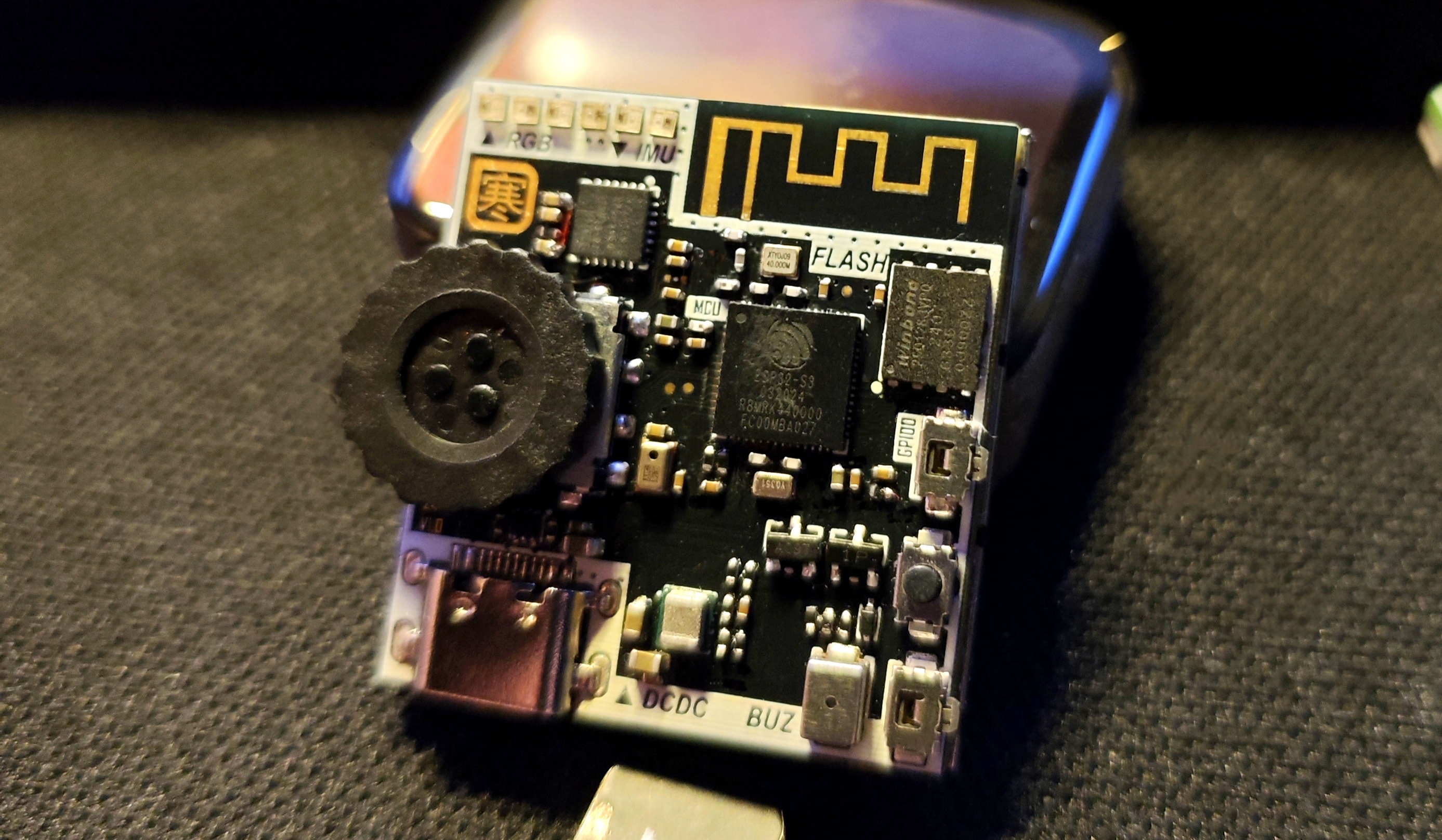
EEOne_ESP32 Development Board
This is a development board based on the ESP32S3, featuring an onboard buzzer, RGB lights, microphone, gyroscope, roller encoder, and a 1.54-inch color LCD screen. It is compact, exquisite, and easy to replicate, making it suitable for learning microcontrollers.
This is a development board that uses the ESP32S3 (optional ESP32S3R2 and ESP32S3R8, with a floating PSRAM pin on the circuit) as the main control chip. I used it for learning and developing example programs. It
has an exquisite appearance and a clear structure. The schematic diagram includes supplementary explanations of the circuit
. Below are some suggestions for replicating it:
First, some component connections —>
Screen address (click)
Roller encoder address (click)
Buzzer address (click)
Microphone address (click)
RGB LEDs can be found on the LCSC website, model WS2812E-1313.
Note! If you only have a soldering iron and no heating element, you should reconsider.
This board cannot be soldered without a heating element. A recommended configuration is a soldering iron + heating element + hot air gun.
Remember to use enough flux! Remember to use enough flux! Remember to use enough flux!
Due to the board's design, all sides are slightly narrower than the screen. Therefore, please carefully align the components before assembling the screen. Applying tape will make it difficult to move
the board. The screen is a 12-pin soldering type; please do not purchase the wrong one. If you happen to have a 1.54-inch screen, you can check the pinout. Incorrect pinouts will make it difficult to remove
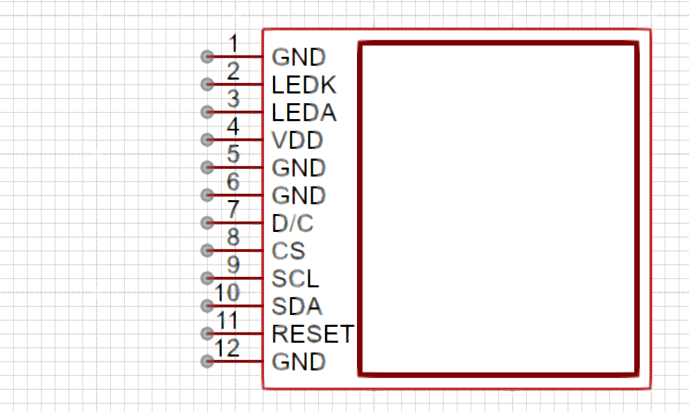
the screen without damage after soldering. The screen uses a MOSFET as the backlight adjustment switch, connected to GPIO14, which can be configured in the program to adjust the backlight brightness.
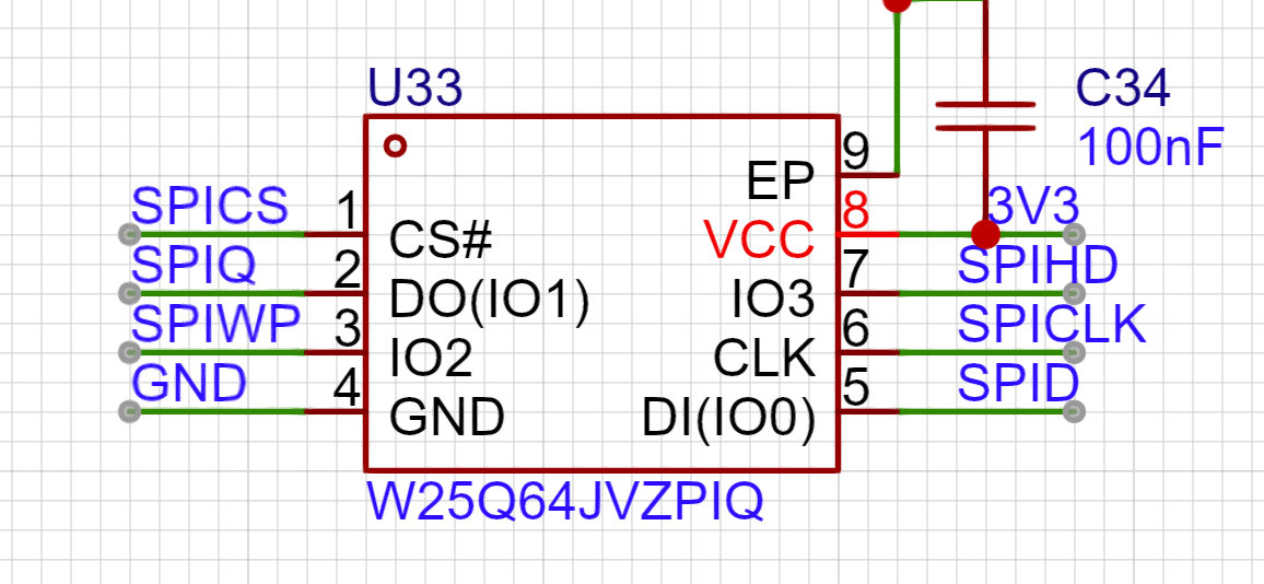
The FLASH chip used on the board has a smaller package than usual; it is a WSON8-6X5. You can choose between W25Q128JVPIQ and W25Q256JWPIQ for replacement.
The microphone is a discontinued silicon microphone; I bought some unused ones when making small toys, so I'm using them as is.
The I2C pull-up resistor can be replaced with a 10K resistor, as long as it's not less than the specified value.
Regarding the power chip, the TI large inductor is used (it's really eye-catching). Its compact size belies its impressive output capability (3A current).
The formula for calculating the output voltage is as follows:
VOUT = VFB X (1 + R1 / R2) = 0.8VX (1 + R1 / R2).
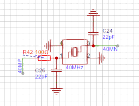
Due to the close proximity of the crystal oscillator to the antenna in the board design, I chose to place a resistor to weaken the crystal oscillator's driving capability, according to Espressif's official documentation. This resistor cannot be omitted or replaced with 0Ω, as shown in the diagram below.
Regarding the onboard buttons, besides the programmable scroll encoder,
GPIO46 and GPIO0 can be pulled down to enable the programming mode. EN enables the mode, and pulling it down stops it from working.
In other words, press and hold SW1 and SW2, then press SW3 to enter programming mode.

Normally, GPIO46 and GPIO0 can be configured separately.
(


A
little note: When soldering, please solder resistors, capacitors, inductors, crystal oscillators, chips, transistors, MOSFETs, buzzers, and other heat-resistant components first.) After cleaning the flux, solder the RGB LEDs, scroll encoder, button switches, and microphone, which are easily damaged. This prevents repeated desoldering and heating from damaging the components. After checking that everything is correct and cleaning off the flux, power on and test all sensors to ensure they are working properly before soldering the screen.
Happy retouching!
I used Thonny to test the onboard sensors and screen, and obtained some libraries from GitHub. The relevant code will be uploaded to the attachment.
(Wanhan, August 4, 2024)
The demo will use a .zip file.
Marquee 1.mp4
Marquee 2.mp4
PDF_EEOne_ESP32 Development Board.zip
Altium_EEOne_ESP32 development board.zip
PADS_EEOne_ESP32 development board.zip
BOM_EEOne_ESP32 Development Board.xlsx
91656
Compatible with Zhengdian STM32F103ZET6 minimum system
Compatible with Zhengdian Atom STM32ZET6 minimum system board
Compatible with Zhengdian Atom STM32ZET6 minimum system board, 4-layer board design. Supports one-click serial port download.
The drawing isn't very good; you can affectionately call it "a lump."
Valuable suggestions are greatly appreciated .
JLCPCB doesn't check this page often; if you need it urgently, you can contact me via email: hhss30804981@163.com
VID_20241016_102533.mp4
VID_20241016_102405.mp4
October 16.mp4
PDF_Compatible with Zhengdian STM32F103ZET6 Minimum System.zip
Altium-compatible STM32F103ZET6 minimum system.zip
PADS_Compatible STM32F103ZET6 Minimum System.zip
BOM_Compatible with Zhengdian STM32F103ZET6 Minimum System.xlsx
91657
electronic


 京公网安备 11010802033920号

 Q62702-F1574


