Project Overview:
This project is based on the ESP8266 and is a simple information display device for desktop placement. It uses components in larger packages such as 0805, which are easy to solder and convenient for teaching. The
project cost is approximately 25 yuan, with the major expenses being the screen and main controller. The screen costs approximately 10 yuan, and the main controller costs approximately 4 yuan.
Project Functionality:
This project is a desktop mini-TV project based on the ESP8266, used to display emoticons, clock, weather, and Bilibili personal information. Users can switch interfaces using buttons, and long-pressing a button in the emoticon interface allows switching emoticons.
✅Emoji Display
✅Clock Display
✅Daily Weather
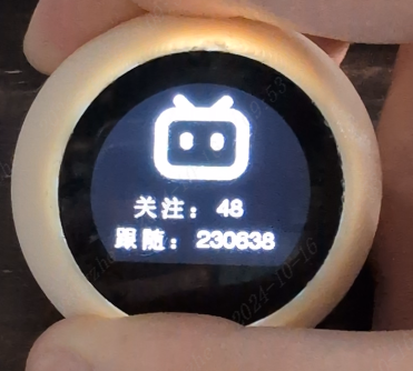
✅Bilibili Information
Project Parameters
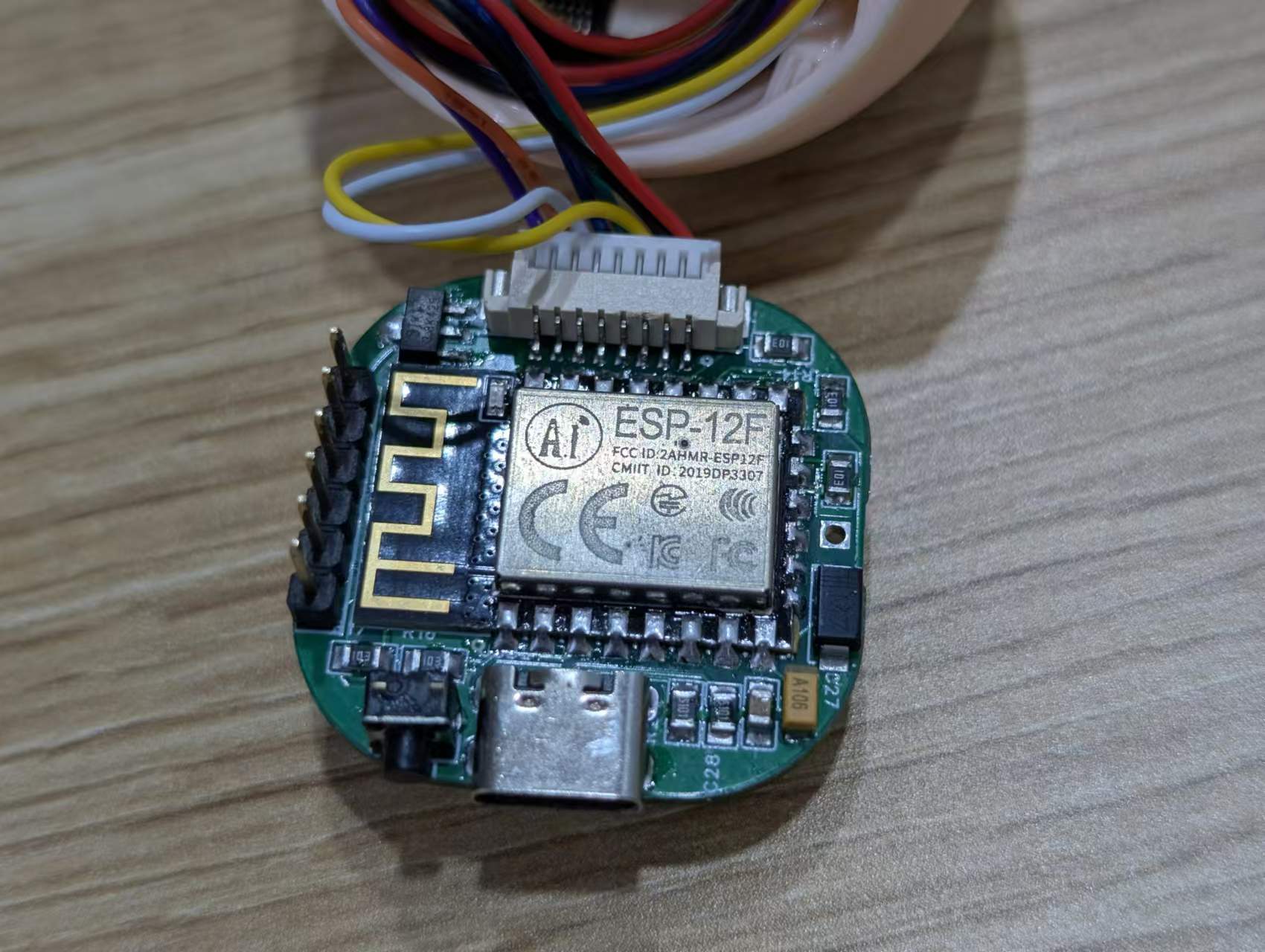
This design uses an ESP8266 main controller with built-in WIFI to complete network requests;
it uses an ST7789 0.96-inch circular LCD display to show emojis, clock, weather, Bilibili information, etc.;
an AMS1117 LDO linear regulator is used to convert 5V to 3.3V to power the main controller;
the Type-C interface has a 5.1K resistor and supports dual Type-C cable power input;
Development Documentation
Online Documentation:
JLCPCB EDA Wiki
Offline Documentation:
Please see the attachment 【TV-Lite Small TV Development Documentation.pdf】
Principle Analysis (Hardware Description)
The circuit of this project consists of the following parts: power supply section, ESP8266 main controller, and external interface
power circuit:
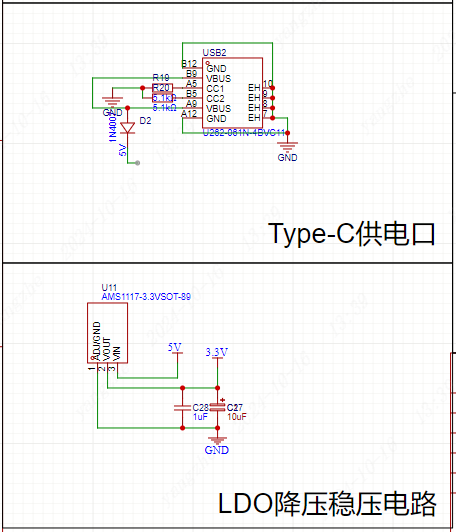
Power Supply Interface: Uses a TYPE-C-6P interface with large pads for easy soldering. 5.1K pull-down resistors are added to the CC1 and CC2 pins for easy identification and configuration by different hosts, supporting dual Type-C cable power supply. A diode is added at the 5V power supply input to prevent reverse voltage from the battery from damaging the Type-C port's power supply.
Voltage regulator: An AMS1117 linear regulator is used to convert the 5V voltage to 3.3V, providing power to the ESP8266 main controller and LCD screen.
Main controller circuit:

Referencing the ESP8266 datasheet, pull-up pins IO0, IO2, EN enable, and RST reset are configured, while the CS chip select signal is pulled down to ensure normal ESP8266 and SPI communication.
External interface circuit:

Screen: Due to space limitations and for ease of replication, a 0.96-inch ST7789 LCD module is used. This module has its own screen driver circuit; only interface connection is required. The corresponding interface pinout is configured according to the screen module's pinout; it can be used directly upon insertion.
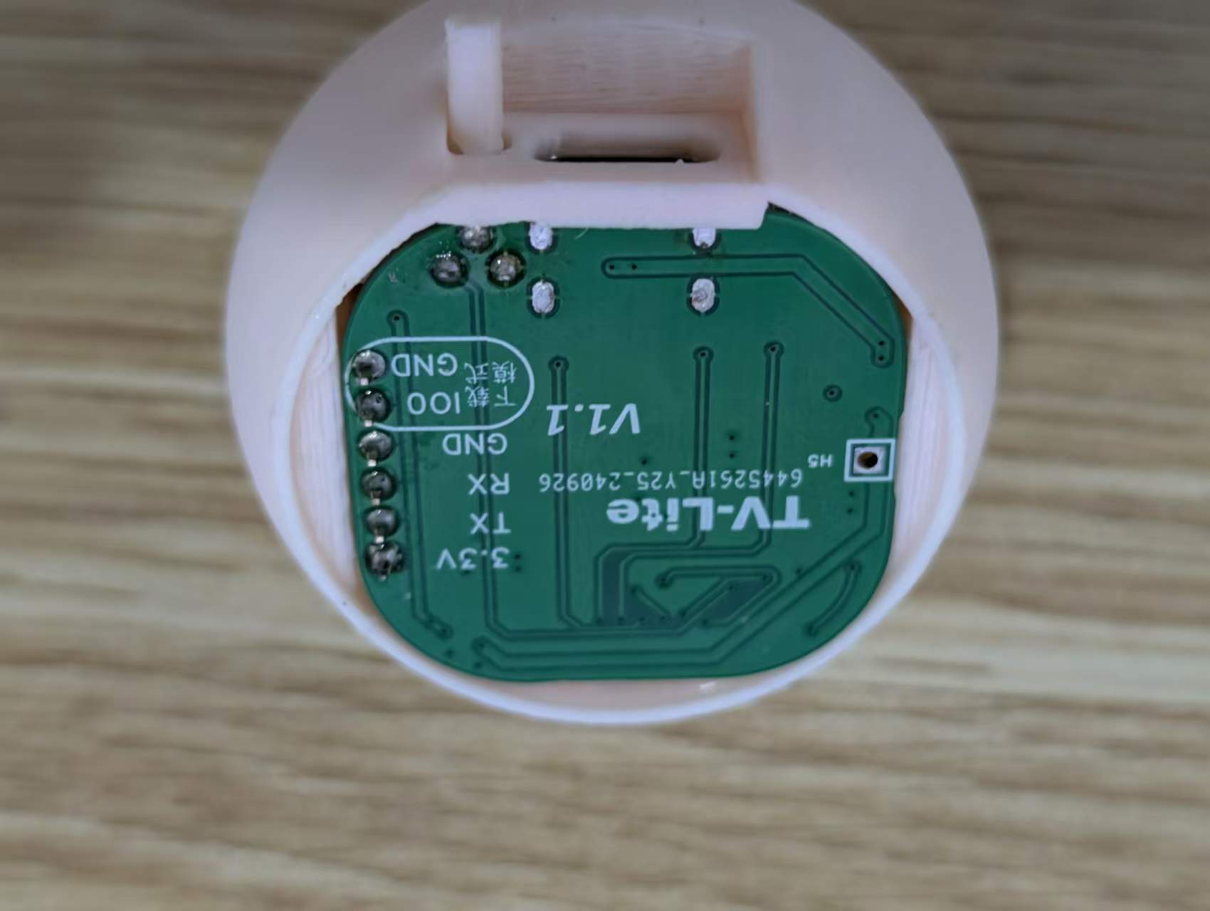
Serial port: For convenient downloading, the serial port has a separate IO0 and GND interface as a jumper insertion interface. When a jumper is inserted, IO0 is pulled low, entering download mode. Conversely, the main control circuit pulls the voltage high, entering the working mode.
Battery: The battery section has a 5V circuit. Due to layout limitations, users who wish to use battery power can purchase and connect a charge/discharge module.
Buttons: The buttons use the IO2 pin; the button is pulled low when pressed and pulled high when idle. The complete project file
with the software code
is attached, along with the directly programmable binary and file system binary files, which can be downloaded.
Due to time constraints, the program still contains some redundant and low-level code logic. There are many areas where resource consumption can be optimized.
The network configuration code can be modified.
`void handleWiFiConfig() {
server.on("/", HTTP_GET, [](AsyncWebServerRequest *request) {
if(SPIFFS.exists("/index.html")) {
fs::File file = SPIFFS.open("/index.html", "r");//Read from the FS file system
if(file) {
size_t fileSize = file.size();
String fileContent;
while(file.available()) {
fileContent += (char)file.read();
}
file.close();
request->send(200, "text/html", fileContent);
return;
}
}
request->send(404, "text/plain", "File Not Found");
});
server.on("/connect", HTTP_POST, [](AsyncWebServerRequest *request) {//Web service receives
String ssid =` request->getParam("ssid", true)->value();
String pass = request->getParam("pass", true)->value();
String uid = request->getParam("uid", true)->value();
String city = request->getParam("city", true)->value();
String api = request->getParam("api",`true)->value();
// Save WiFi information to file
DynamicJsonDocument doc(1024);
doc["ssid"] = ssid;`
In the program, the ESP8266 reads an HTML webpage from
the FS file system and
mounts it to its local network port. Users can then access the HTML network configuration page via 192.168.4.1 by connecting to the hotspot. The user -submitted form is returned to the ESP8266 via a POST request . To prevent users from repeating the same steps after a reboot, the form information needs to be saved in JSON format to the FS file system for direct reading upon the next boot, thus avoiding repetitive and tedious network configuration operations. Then, simply enter the WiFi name and password in the WiFi.begin method to connect to the WiFi network. HTML code for the webpage :
Create a new folder named "data" in the project directory, create a file named "index.html", and write the HTML code for the network configuration webpage. In this code, a form is created, containing input boxes for WiFi name, password, bilibili user ID, Xinzhi Weather API, and city weather (lowercase). After the user clicks "submit", the information is securely passed to the program via the POST method, and the program reads the information from the "name" field in the input box. FLASH read/write storage code void loadWiFiConfig() { if (SPIFFS.begin()) { fs::File file = SPIFFS.open(ssidFile, "r"); if (file) { DynamicJsonDocument doc(1024); DeserializationError error = deserializeJson(doc, file); if (!error) { String ssid = doc["ssid"]; String pass = doc["pass"]; String uid = doc["uid"];
String city = doc["city"];
String api = doc["api"];
useruid=uid;
cityname=city;
weatherapi=api;
WiFi.begin(ssid.c_str(), pass.c_str());
// Attempt to connect to WiFi, wait up to 10 seconds
unsigned long startAttemptTime = millis();
while (WiFi.status() != WL_CONNECTED && millis() - startAttemptTime < 5000) {
delay(500);
}
// If the connection fails, print the status
if (WiFi.status() != WL_CONNECTED) {
Serial.println("WiFi connection failed, starting captive portal...");
startCaptivePortal();
} else {
Serial.println("WiFi connected");
timeClient.begin();
}
}
file.close();
}
}
Previously
, we mentioned how to configure the network via Wi-Fi and save the data to the FS file system in JSON format. Therefore, reading the configuration information here is relatively easy. Simply read the JSON data and then follow the steps to start the Wi-Fi connection.
Screen Wiring Settings
: #define USER_SETUP_INFO "User_Setup"
#define ST7789_DRIVER // Full configuration option, define additional parameters below for this display
#define TFT_RGB_ORDER TFT_BGR // Colour order Blue-Green-Red
#define TFT_WIDTH 240 // ST7789 240 x 240 and 240 x 320
#define TFT_HEIGHT 198
#define TFT_BL 4 // LED back-light control pin
#define TFT_BACKLIGHT_ON HIGH // Level to turn ON back-light (HIGH or LOW)
#define TFT_MOSI 13
#define TFT_SCLK 14
#define TFT_CS 15 // Chip select control pin
#define TFT_DC 5 // Data Command control pin
#define TFT_RST -1 // Set TFT_RST to -1 if display RESET is connected to ESP32 board RST
#define LOAD_GLCD // Font 1. Original Adafruit 8 pixel font needs ~1820 bytes in FLASH
#define LOAD_FONT2 // Font 2. Small 16 pixel high font, needs ~3534 bytes in FLASH, 96 characters
#define LOAD_FONT4 // Font 4. Medium 26 pixel high font, needs ~5848 bytes in FLASH, 96 characters
#define LOAD_FONT6 // Font 6. Large 48 pixel font, needs ~2666 bytes in FLASH, only characters 1234567890:-.apm
#define LOAD_FONT7 // Font 7. 7 segment 48 pixel font, needs ~2438 bytes in FLASH, only characters 1234567890:-.
#define LOAD_FONT8 // Font 8. Large 75 pixel font needs ~3256 bytes in FLASH, only characters 1234567890:-.
#define LOAD_GFXFF // FreeFonts. fonts
#define SMOOTH_FONT
#define SPI_FREQUENCY 40000000
#define SPI_READ_FREQUENCY 20000000
#define SPI_TOUCH_FREQUENCY 2500000
#define USE_HSPI_PORT
For ease of use, the screen uses the TFT-eSPI library, configured as shown in User_Setup.h. However, since we are using a non-circular screen, some driver-level methods need to be modified.
The screen display definition
is added to ST7789_Defines.h with a 198x240 screen display definition.
//0.96 circle TFT support
#if (TFT_HEIGHT == 198) && (TFT_WIDTH == 240)
#ifndef CGRAM_OFFSET
#define CGRAM_OFFSET
#endif
#endif
The screen rotation definition is added
to ST7789_Rotation.h. Under
case 2:, add
else if(_init_height == 198)
{
colstart = 0;
rowstart = 122;
}
Under case 3:, add
else if(_init_height == 198)
{
colstart = 122;
rowstart = 0;
}
Key code
void IRAM_ATTR handleButtonPress() {
unsigned long currentTime = millis();
if (digitalRead(buttonPin) == LOW && !buttonPressed) { // Detect button press and not recorded as pressed
buttonPressed = true;
pressStartTime = currentTime; // Record the time when pressed
}
// Detect if it is a long press
if (buttonPressed && (currentTime - pressStartTime) > LONG_PRESS_DELAY) {
isLongPress = true;
}
// Detect if button is released
if (digitalRead(buttonPin) == HIGH && buttonPressed) {
if (isLongPress) { // If it is a long press
if (currentPage == 0) { // Only switch emojis on the first page
emojiState = (emojiState + 1) % 8; // The code snippet
`mylcd.fillScreen(TFT_BLACK); // Clear screen
}
} else { // If it's a short press
if (currentTime - lastDebounceTime > debounceDelay) {
currentPage = (currentPage + 1) % 4; // Short press to switch pages
lastDebounceTime = currentTime;
mylcd.fillScreen(TFT_BLACK); // Clear screen
}
}
// Reset button state
buttonPressed = false;
isLongPress = false;
}
mylcd.fillScreen(TFT_BLACK); // Clear screen
}`
demonstrates how to ensure an immediate response when a button is pressed. This interrupt operation ensures that the program immediately performs the page-turning operation when a button is pressed, without waiting for the current page's program to finish executing, thus providing a fast response.
Since the logic for switching emojis involves a long press on the emoji page, a timer is needed to monitor the duration of the button press to determine whether it's a long press or a short press. An `if` statement is used to determine if the long press occurred on the emoji page and not another page.
Finally, a full-screen black screen needs to be added to refresh the screen, ensuring that the content of the previous page is cleared before the next page.
Page function code
void bilibili() {
if (initbilibili==false) {
mylcd.fillScreen(TFT_BLACK);
if (WiFi.status() == WL_CONNECTED) {
WiFiClientSecure client;
client.setInsecure();
HTTPClient http;
if (http.begin(client,bilibiliAPI+useruid)) {
int httpCode = http.GET();
if (httpCode > 0) {
String payload = http.getString();
Serial.println("JSON Response:");
Serial.println(payload);
DynamicJsonDocument doc(1024);
deserializeJson(doc, payload);
String following2 = doc["data"]["following"];
// Accessing data key
String follower2 = doc ["data"]["follower"]; following
=following2; follower
=follower2 ;
initbilibili = true ; http.end(); } else { Serial.println("Failed to connect to server"); } mylcd.fillScreen(TFT_BLACK); } mylcd.pushImage(mylcd.width() / 2-(99/2), 10, 99, 99,bilibiliimg); mylcd.pushImage(50, 125, 25, 25,guan); mylcd.pushImage(80, mylcd.pushImage ( 60 , 160, 25, 25,sui); mylcd.pushImage(90, 160, 25, 25, maohao); mylcd.drawString(follower, 120, 160, 4); } } This code snippet uses the functional code from the BiliBili page. First, it clears the screen to ensure the previous page's content is erased. Then, it checks the network connection. If the connection is successful, it starts HTTPClient, sends a GET request to the online server, receives the returned JSON value, parses it, and stores it. Then, it closes the HTTP request and executes the screen display code. Because images are used in the screen display, it first uses `mylcd.pushImage` to output the `bilibiliimg` image from `image.cpp` (included in the header file) to the upper center of the screen. It then uses `mylcd.width()` to get the screen width divided by 2, and then subtracts the image width divided by 2. Similarly, it outputs the image and text sequentially, and then uses `mylcd.drawString` to output the String type text (of course, other formats can also be used; refer to the previously stored value format for details). Finally, let's explain why `initbilibili == false` was used at the beginning. This is to ensure that the page's program executes only once, avoiding screen flickering and allowing for faster program response, essentially converting a dynamic page into a static one. The UI logic code is as follows: `switch (currentPage) { case 0: // Homepage initbilibili = false; switch (emojiState) { case 0: mylcd.pushImage(mylcd.width() / 2-(200/2), mylcd.height()/2-(100/2), 200, 100,hi); // Emoji 1 break; case 1: }`
mylcd.pushImage(mylcd.width() / 2-(200/2), mylcd.height()/2-(100/2), 200, 100,nice);// Expression 2
break;
case 2:
mylcd.pushImage(mylcd.width() / 2-(200/2), mylcd.height()/2-(100/2), 200, 100,mid);//expression 3
break;
case 3:
mylcd.pushImage(mylcd.width() / 2-(200/2), mylcd.height()/2-(100/2), 200, 100,unhappy);
break;
case 4:
mylcd.pushImage(mylcd.width() / 2-(200/2), mylcd.height()/2-(100/2), 200, 100,error);
break;
case 5:
mylcd.pushImage(mylcd.width() / 2-(200/2), mylcd.height()/2-(100/2), 200, 100,star);
break;
case 6:
mylcd.pushImage(mylcd.width() / 2-(200/2), mylcd.height()/2-(100/2), 200, 100,love);
break;
case 7:
mylcd.pushImage(mylcd.width() / 2-(200/2), mylcd.height()/2-(100/2), 200, 100,what);
break;
case 8:
mylcd.pushImage(mylcd.width() / 2-(200/2), mylcd.height()/2-(100/2), 200, 100,dowhat);
break;
}
break;
case 1: // Second page
if (WiFi.status() != WL_CONNECTED) {
Serial.println("Starting captive portal...");
mylcd.pushImage(mylcd.width() / 2-(99/2), 10, 99, 99,wifi);
mylcd.drawString("WIFI:TV-Lite", 50, 125, 4);
mylcd.drawString("IP:192.168.4.1", 40, 155, 4);
}else {
showClockPage(); // Display clock
}
break;
case 2: // Third page
if (WiFi.status() != WL_CONNECTED) {
Serial.println("Starting captive portal...");
mylcd.pushImage(mylcd.width() / 2-(99/2), 10, 99, 99,wifi);
mylcd.drawString("WIFI:TV-Lite", 50, 125, 4);
mylcd.drawString("IP:192.168.4.1", 40, 155, 4);
}else {
initialized = false;
fetchWeather(); // Get the weather
}
break;
case 3: // Fourth page
if (WiFi.status() != WL_CONNECTED) {
Serial.println("Starting captive portal...");
mylcd.pushImage(mylcd.width() / 2-(99/2), 10, 99, 99,wifi);
`mylcd.drawString("WIFI:TV-Lite", 50, 125, 4);
mylcd.drawString("IP:192.168.4.1", 40, 155, 4);
}else {
initweather = false;
bilibili(); // Display the bilibili page
}
break;
}`
The page logic is relatively simple, using a switch statement to determine the page number.
Additionally, to ensure no issues arise when the user is offline, a WIFI status check is added, prompting the user to configure the network when online functions are offline.
Finally, `initxxx = false;` needs to be added at the end of each page to ensure that the page's functionality is initialized upon the next page entry.
Panel Design:
There are two types of 0.96-inch circular LCD displays on the market: one with a glass cover and one without. For users who prefer customization, a suitable personalized panel template is provided, which can be customized through LCSC Panel Maker.
3D Shell Design:
This project is compatible with a corresponding circular FDM printed shell. The shell has a fixing slot for easy mounting of the circuit board. The cover is secured primarily by the friction of the layer textures. The shell has been verified on an FDM 3D printer.
Precautions:
Ensure the power supply voltage is 5V. Do not use other voltage values.
Device configuration address: 192.168.4.1. Please connect to the Wi-Fi network first, then access this address.
The weather API used is the Xinzhi Weather API, which is a free API. Please register on the official website to obtain the API key and enter it into the configuration address. The
clock interface may be out of sync upon initial startup; please wait a moment. Assembly Process:
The assembly process is relatively simple, requiring only a motherboard, a connecting cable, a screen, and a shell.
First, connect one end of the connecting cable to the screen.
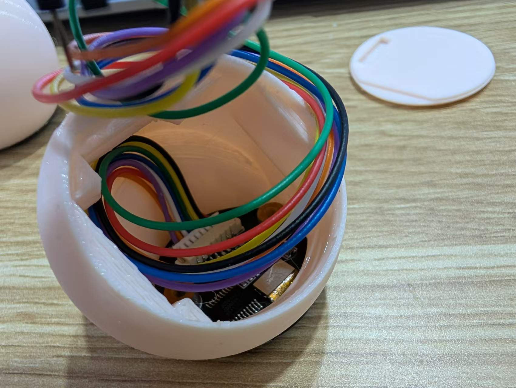
Second, thread the cable through the shell and secure the screen with glue.
Finally, insert the cable into the shell, insert the motherboard into the limiting slot, and then close the bottom cover according to the opening.
Image
1:
Emoji Page;

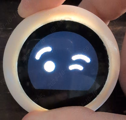
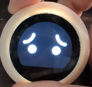
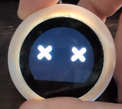
Image 2: Clock Page;
Image 3: Weather Page;


Image 4: Bilibili Page.
Attachment Description :
【TV-Lite.zip】: Program Source Code;
【firmware.bin】: Program Firmware;
【spiffs.bin】: FS File System Firmware;
【TV-Lite.SLDASM】: Combined File;
【TV-Lite.SLDPRT】: Shell Source File;
【TV-Lite_Bottom.SLDPRT】: Bottom Shell Source File ;
【TV-Lite_KEY.SLDPRT】: Button Growth Source File;
【TV-Lite.stl】: Shell 3D File; 【TV-
Lite_Bottom.stl】: Bottom Shell 3D File;
【TV-Lite_KEY.stl】: Button Growth 3D File.
Notes : For the 3D shell, it is recommended to use an FDM printer. For the OLED display, a 0.96-inch round screen
is recommended. For the buttons, it is recommended to purchase 2.5x2.5x10mm, which does not require growth.


 京公网安备 11010802033920号

 CSWM9125


