This is a rotary encoder module:
The basic internal schematic is as follows:
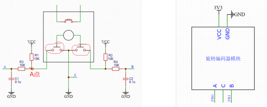
The two unconnected pins at the top are a switch, which is the switch used when the encoder is pressed down. It can be connected to the circuit if needed.

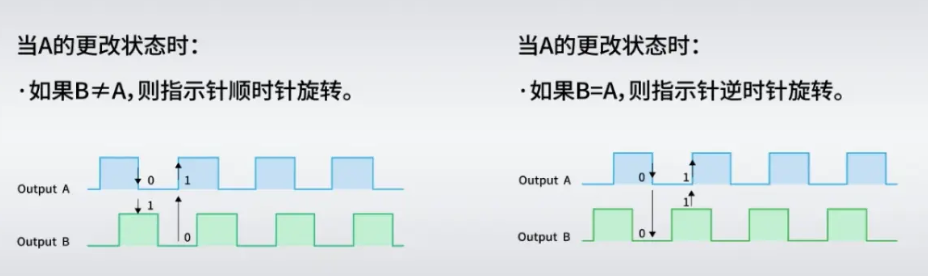
The principle is as follows:

The physical diagram is as follows:

The schematic diagram is as follows: My switch pins D and E are not connected; you can connect them based on my schematic diagram if needed.

The 3D diagram is as follows:

PDF_encoder module.zip
Altium_encoder_module.zip
PADS_encoder module.zip
BOM_14.EncoderModule.xlsx
91695
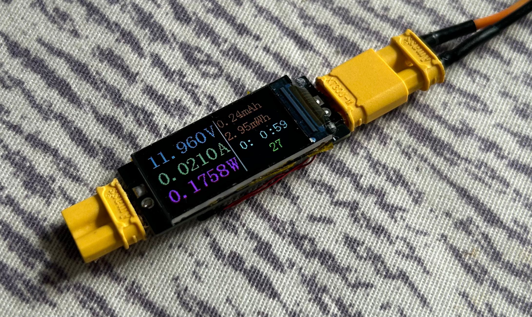
Ultra-small and easy-to-use current and voltage meter
Thanks to @wffg for the open-source project. This project is characterized by its extremely small size, lack of a USB-C port, and low cost.
This is a cloned and modified version of the simple ammeter project by @wffg, with only the PCB modified. Thanks to the open-source
project for its features:
ultra-small (only the size of a 0.96-inch TFT screen)
, minimalist design, no CC port (can be used as a meter head),
inexpensive, and needs no further explanation
. Notes on replicating:
When soldering the TFT screen, each pin needs to be soldered individually; the temperature should not be too high;
the back of the screen needs to be insulated; the windowed area needs to be tinned to meet overcurrent requirements.
For the BOM (Bill of Materials), please be sure to open the schematic and purchase the meter yourself.
Except for the sampling resistor, all resistors and capacitors use 0603 for easy soldering.
See the original project for more details.
jdf9.hex
PDF_Miniature and Simple Current and Voltage Meter.zip
Altium_Miniature Simple Current and Voltage Meter.zip
PADS_Ultra-small and easy-to-use current and voltage meter.zip
BOM_Ultra-small and easy-to-use current and voltage meter.xlsx
91696
LED current limiting resistor selection test
Visually observe the corresponding LED brightness under different sizes of current-limiting resistors.
In engineering applications, LEDs are often used to indicate the operating status of a PCB, such as power-on and communication. However, a troublesome problem is that improper selection of the current-limiting resistor can result in LEDs that are too bright or too dim, severely impacting the visual experience (especially being blindingly bright). The purpose of this board is to visually demonstrate the corresponding LED brightness under different current-limiting resistor sizes, manually adjust it to a satisfactory brightness, and then apply it to my own project.
3ab6c4eaaa8ffc6a26f802cbc80f204f.mp4
PDF_LED Current Limiting Resistor Selection Test.zip
Altium_LED Current Limiting Resistor Selection Test.zip
PADS_LED Current Limiting Resistor Selection Test.zip
BOM_LED Current Limiting Resistor Selection Test.xlsx
91697
STC32 Development Board
Learn how to use STC32G12K128
Introduction:
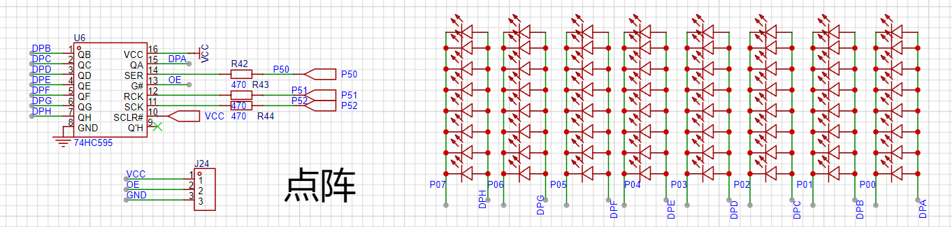
This project is a learning board based on the STC89C51/52 microcontroller. It features a USB direct programming port, infrared, dot matrix, motor driver, LCD, OLED, buzzer, NRF24L01 interface, DS18B20 module, and digital tube circuitry.

Functionally,
this design is based on the STC89C51/52 microcontroller. It has four independent buttons, all with customizable functions. Pins are brought out using headers. Most circuit modules can be used simultaneously.


Appropriate screen learning

software can be selected according to requirements. The software code
is included in the project attachments.
BOM_Board1_Schematic1_2024-10-14.xlsx
Program source code (2).zip
PDF_STC32 development board.zip
Altium_STC32 development board.zip
PADS_STC32 development board.zip
BOM_STC32 development board.xlsx
91698
ESP32-C3FH4 Development Board
Development board based on Espressif ESP32-C3FH4
This development board is based on the Espressif ESP32-C3FH4 microcontroller, with a 160MHz main frequency, 4MB of built-in Flash memory, an onboard ceramic antenna, and a USB port on the C3 microcontroller for programming. Its dimensions are 27.95*36.6mm. All resistors and capacitors on the board are 0603 packages for easy manual soldering.
To ensure signal quality, please select the free 3313 ±20% impedance control
. [Images: ![IMG_20241013_133730.jpg]
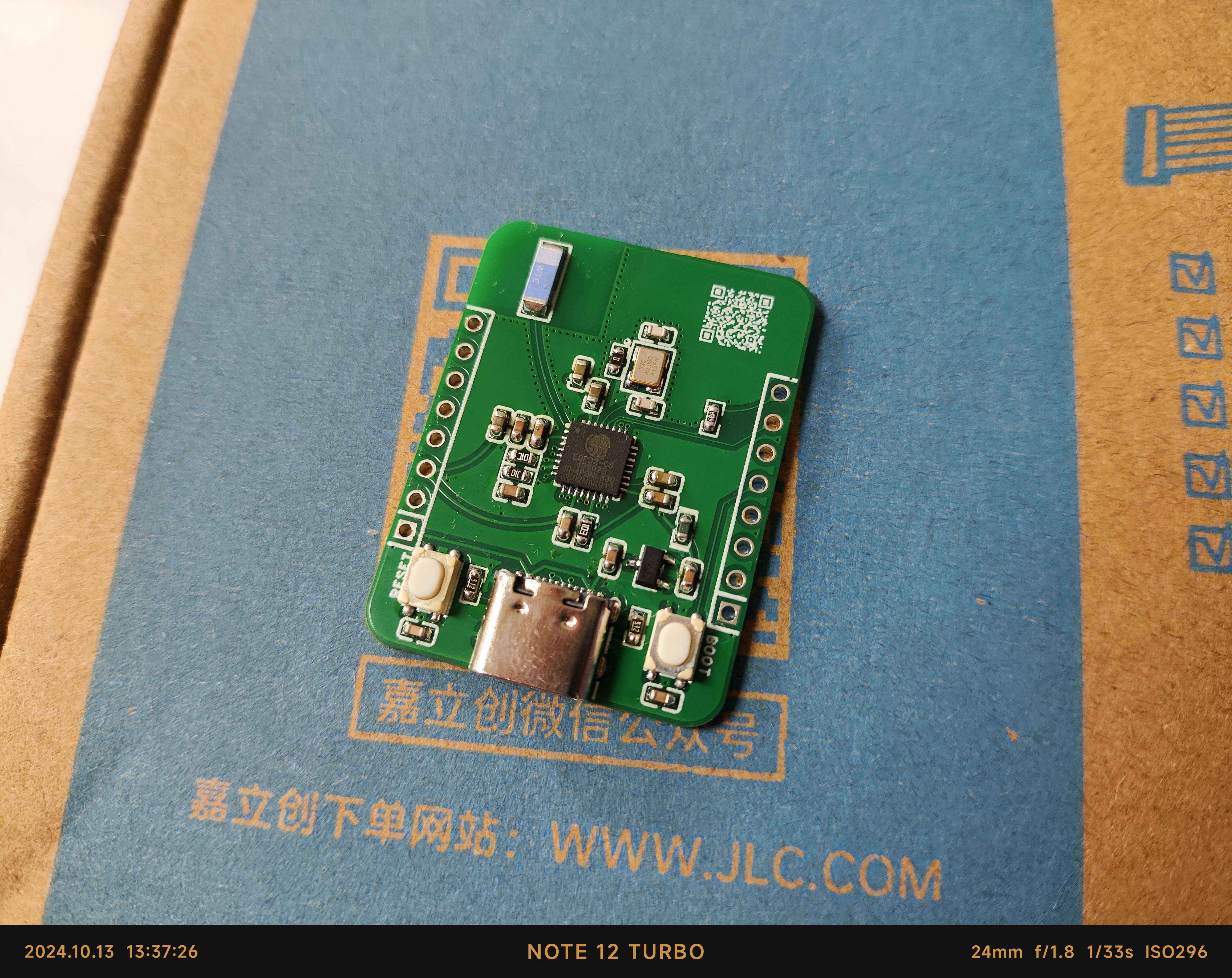
![IMG_20241013_130954.jpg]]

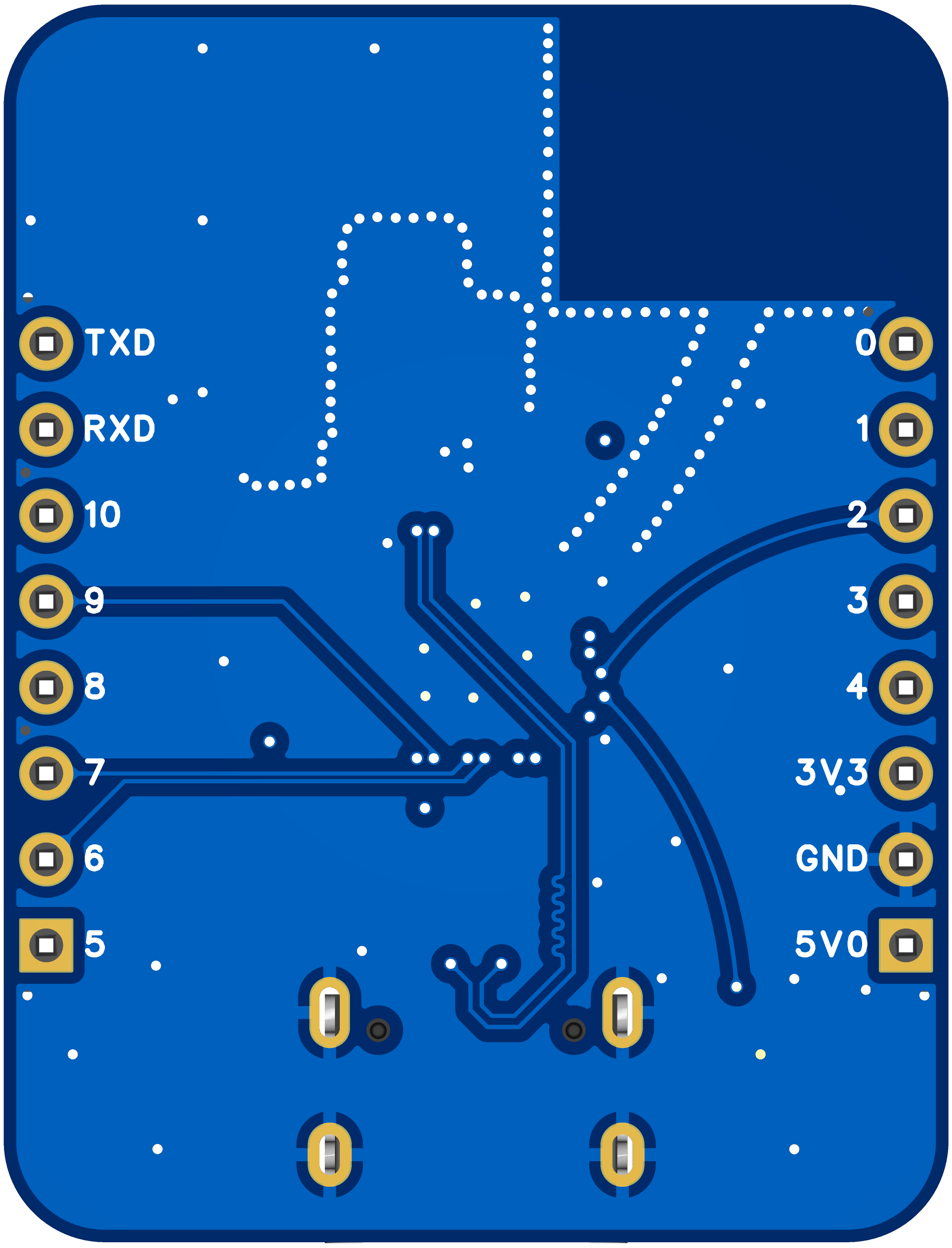
Pin diagram: [Image:
![3D_PCB26_2024-10-13.png]]
PDF_ESP32-C3FH4 development board.zip
Altium_ESP32-C3FH4 development board.zip
PADS_ESP32-C3FH4 development board.zip
BOM_ESP32-C3FH4 Development Board.xlsx
91699
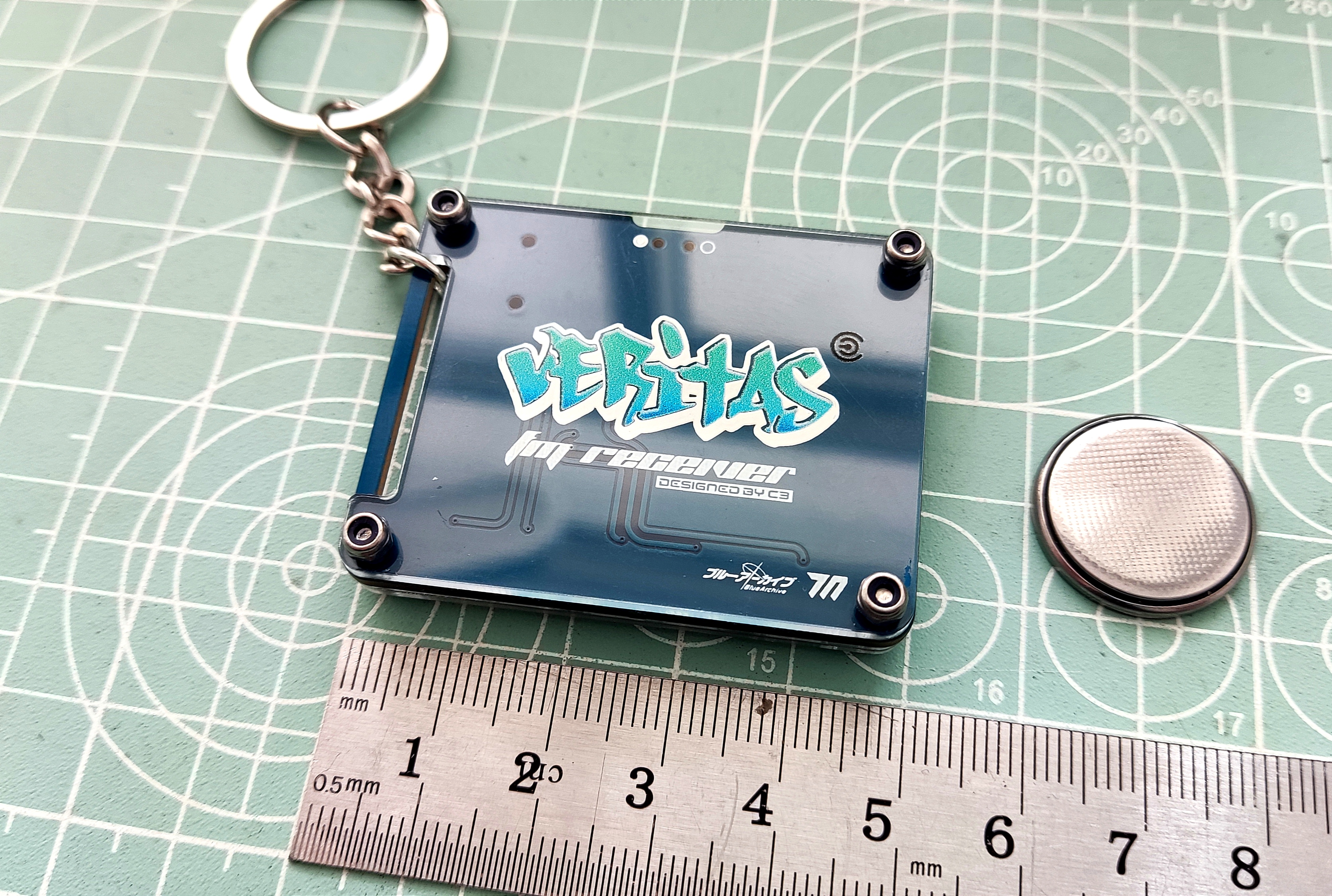
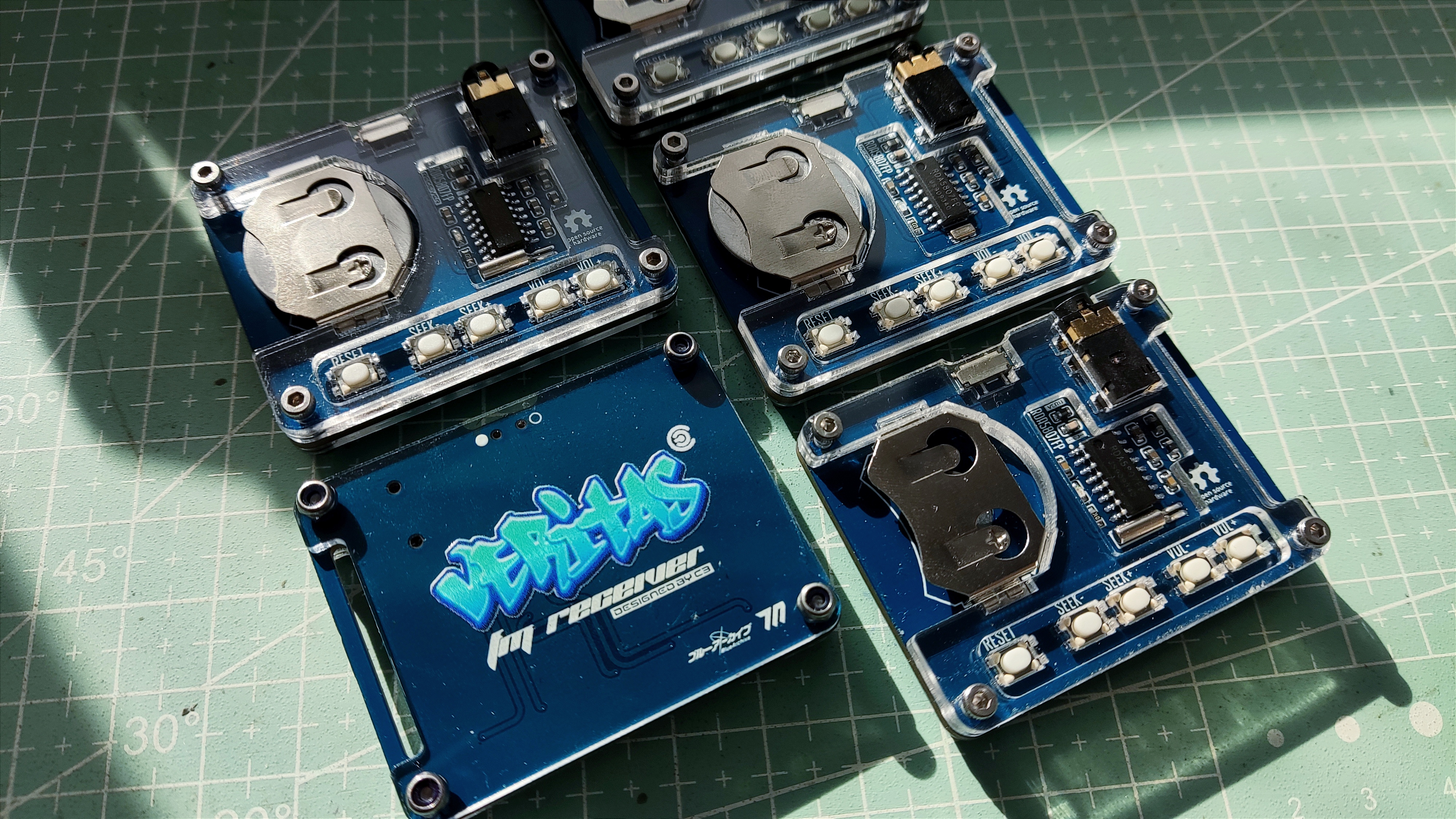
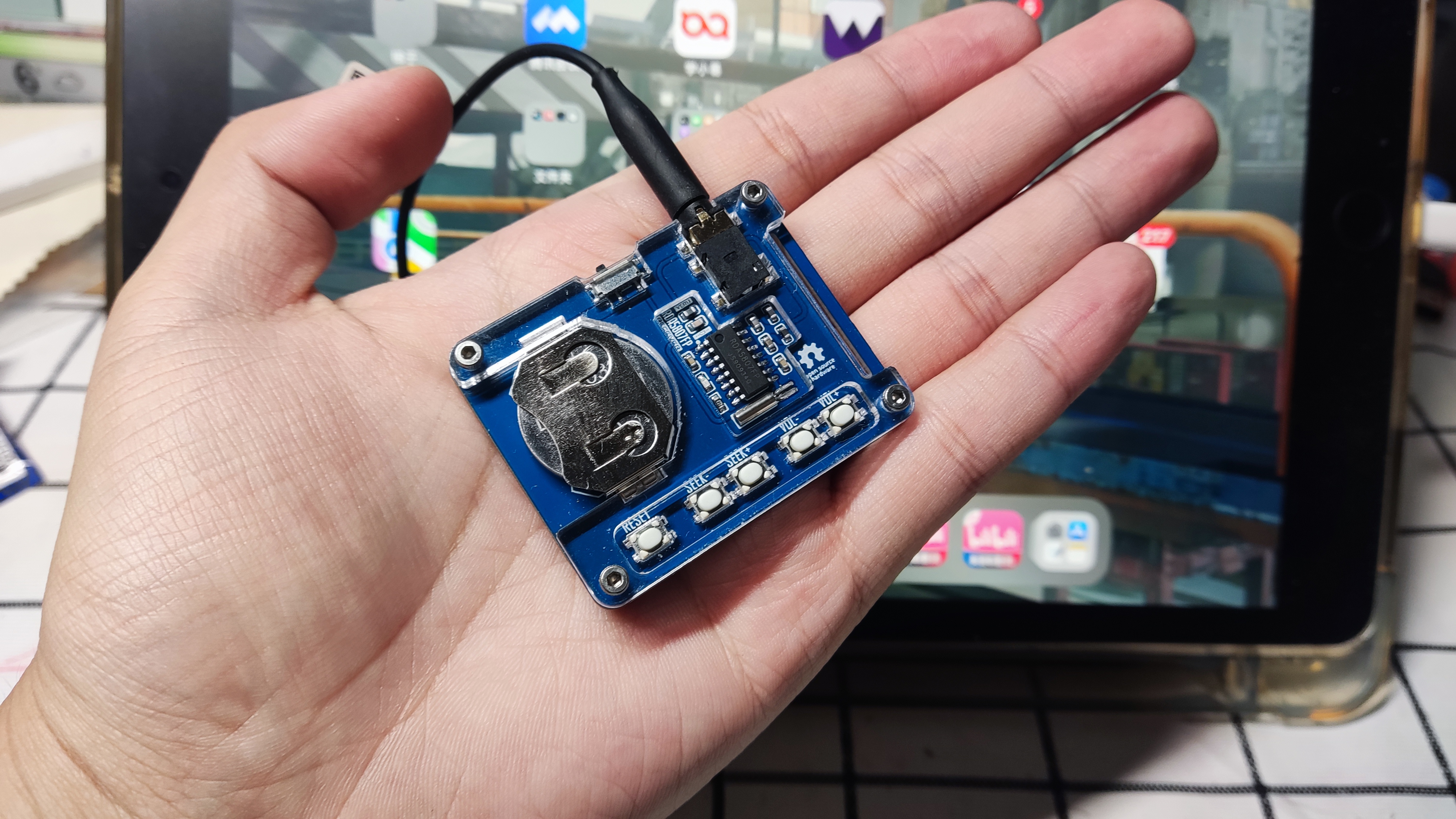
RDA5807FP Card Radio - VERITAS
This mini card radio, based on the RD5807FP, has undergone peripheral optimization and can receive FM frequencies using headphones as an antenna. The direct output sound is still quite pure.
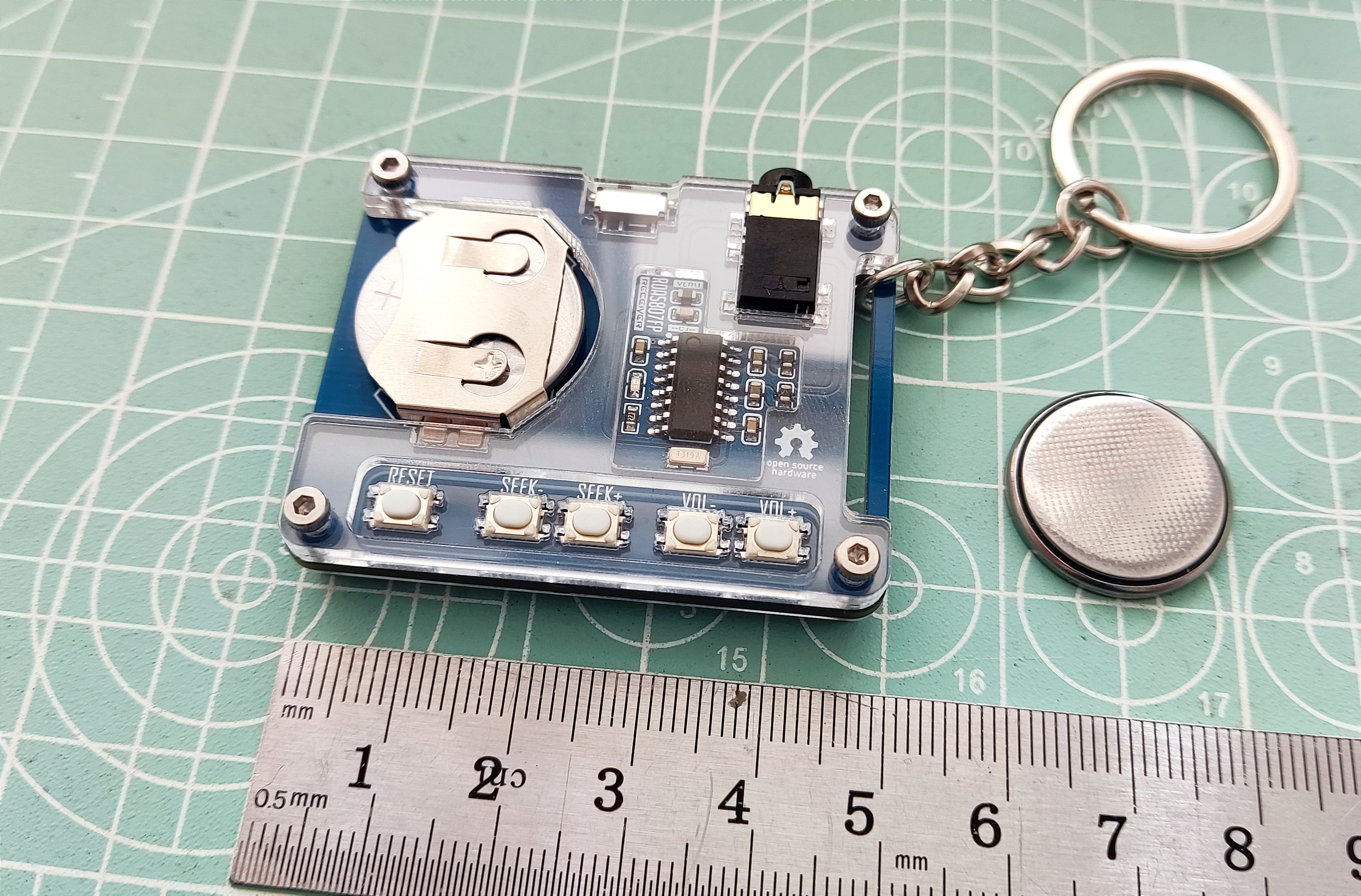
This project is a simple RDA58087FP card radio, powered by CR2032 batteries and using an earphone cable as the antenna. It provides basic FM radio functionality.
I've also added a small custom design element: a small acrylic radio keychain combining a blue-architectural Beritas-style back panel and front panel. No programming is required; simple soldering is all it takes. It's suitable for beginners practicing soldering.
Instructions: Insert the batteries and earphones, turn it on, and press seek+ or seek- to automatically search for stations. It will stop when a station is found.
Points to note: 1. It's best to use CR2032 batteries. Rechargeable batteries like LI2032 may have issues with insufficient voltage or short battery life.
2. The front panel printing thickness is 1.5mm. It's best to print from the bottom; the logo will have a glowing effect under side lighting. Thanks to LCSC for their efficient and high-quality front panel printing.
3. Saving the project may revert to the default font. Include a Gerber file in the attachment; you can edit the project with your preferred image. 4.
Hardware includes four M2x9 hex socket screws and four M2 lock nuts.
5. Custom LCSC panel is used; the file is in the project file at the bottom.
To be added.
![1728648876664.jpg]
![1728648876675.jpg]
![1728648876691.jpg]
![1728648876705.jpg]
![1728648876721.jpg]

Gerber_PCB1_Surface Mount Crystal Oscillator_Differential Buttons_Beritas_2024-10-11.zip
PDF_RDA5807FP Card Radio - VERITAS.zip
Altium_RDA5807FP Card Radio - VERITAS.zip
PADS_RDA5807FP Card Radio - VERITAS.zip
BOM_RDA5807FP Card Radio-VERITAS.xlsx
91700
electronic


 京公网安备 11010802033920号

 IP1R1915-V


