The system aims to support peripheral interfaces for
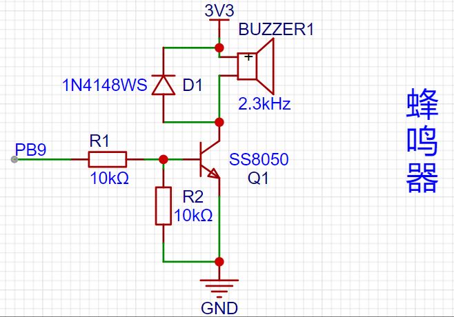
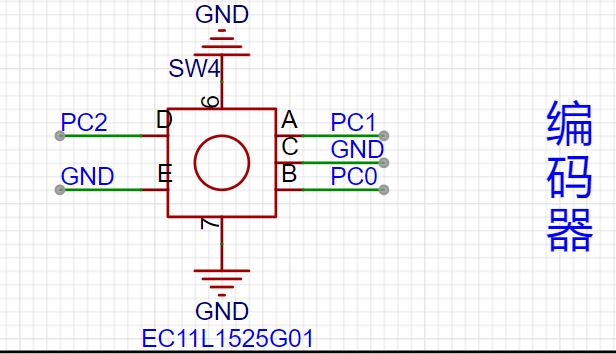
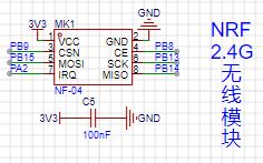
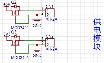
GD32F407VET6, STM32F407VGT6, and HC32F4A0PITB , including: tri-color LEDs, 2.4G wireless modules, motor drive modules, buzzers, rotary encoders, temperature and humidity sensors, OLED display modules, and LCD display modules . Expansion pins include GPIO and power supply interfaces. The interface modules include: 1. Buzzer Module: This module adds a freewheeling diode (to prevent damage from voltage spikes, as buzzers are inductive components) and a transistor. The PB9 pin controls the transistor's on/off state, thus controlling the buzzer's switch. 2. 0.96-inch OLED Module: This 0.96-inch OLED module is compatible with most I2C interfaces on the market and includes a 10K pull-up resistor for stable communication. It uses PB6 and PB7 for communication. 3. 1.8-inch LCD Module : This 1.8-inch LCD module connects directly according to the interface definitions, using GPIOs PA5, PA7, PB0, PB1, PB10, and PD6. 4. Digital Tube Module: The digital tube module uses an AIP650 shift register and a 4-digit digital tube. A filter capacitor has been added to the chip's power supply port. GPIOs used are PD0 and PD1. 5. Encoder Module: The encoder module is relatively simple, directly connected to the microcontroller's GPIOs, with software debouncing. GPIOs used are PC0, PC1, and PC2. 6. Ultrasonic Module: The ultrasonic module's power supply section has added filter capacitors to stabilize the power input. GPIOs used are PC10 and PC11. 7. Temperature and Humidity Module: The temperature and humidity module uses a Sensirion STH41 chip, communicating with the microcontroller via I2C. A 10K pull-up resistor has been added for stable communication. The PCB layout incorporates a cutout design, placing the chip on the bottom to reduce the impact of PCB temperature and dust. GPIOs used are PB8 and PB9. 8. 2.4G Wireless Module: The wireless module has added filter capacitors. GPIOs used are PA2, PB8, PB9, PB13, PB14, and PB15. 9. Motor Module: The motor module features output filtering and a reserved motor interface, with a maximum output current of 1.8A and a peak current of 2.5A. GPIOs used are PD14 and PD15. 10. Power Supply Section: For safety, a PMOS transistor is added for reverse polarity protection, and it should be used only to power peripherals. Software Section: The software development primarily uses KEIL and the STM32 CUBE IDE. Example programs can be found on the LCSC official website: https://wiki.lckfb.com/zh-hans/tkx/. Most of the example code is directly usable, with consistent GPIO pin interfaces, making it very suitable for beginners. [GD32F407VET6 Version] Baidu Cloud link for beginner's manual download: https://pan.baidu.com/s/1CFs39v8Ev3JDlkErcUDglw?pwd=ffff Extraction code: ffff Module porting code download: https://pan.baidu.com/s/1fkPoWqAyFUtIIVbM1sNK2Q?pwd=cbhf Extraction code: cbhf [HC32F4A0PITB Version] Baidu Cloud link for beginner's manual download: https://pan.baidu.com/s/14M6ovaOl71TVgmRD00rIjA?pwd=ef82 Extraction code: ef82 Module porting code download: https://pan.baidu.com/s/1ZeGzmg2KqSkeb-llBn-lw?pwd=g7es Extraction code: g7es [STM32F407VxT6 Version] Baidu Cloud Link : [Standard Library] Introductory Manual Download: https://pan.baidu.com/s/1kDTqSKuQRyudF34XczzIFg?pwd=dc1q Extraction Code: dc1q [Standard Library] Module Porting Code Download: https://pan.baidu.com/s/17XoMY-u3VMqCJ7sFAdpNlQ?pwd=tlub Extraction Code: tlub Note: Due to size limitations, the 1602LCD and optocoupler modules have been removed. The ultrasonic module and the 0.96-inch OLED module cannot be installed simultaneously. The 0.96-inch OLED module is installed using a 4-pin 2.54mm header for easy installation and removal. Power output is used only for output purposes, and reverse polarity protection has been added.


 京公网安备 11010802033920号

 1648660000


