Project Parameters
: Main Controller: STM32H743VIH6
; Gyroscope: 2 ICM42688_P;
Barometer: MS5611;
Magnetic Compass:
IST8310; : SD Card
; OSD: AE7456;
BEC: Supports 8S 12V1.5A 5V1.5A.
Hardware Details
: Main Controller: STM32H743VIH6; Frequency: 480MHz; Flash: 2048MB; RAM: 1024MB; Uses TFBAG100 package, can accommodate 0.45mm balls, relatively easy to solder with soldering skills
. Gyroscopes: Two ICM42688_P, allowing for more redundancy. Compared to the BMI088
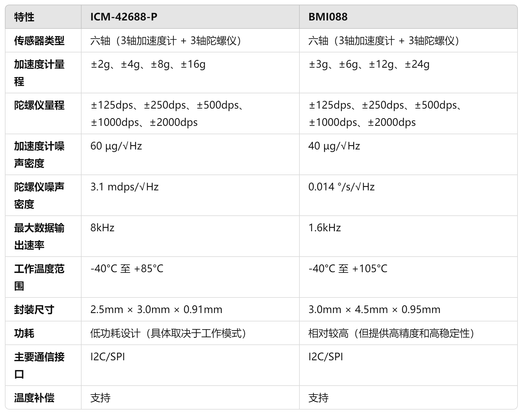
ICM-42688-P, the accelerometer noise density is approximately 60 µg/√Hz, and the gyroscope noise density is approximately 3.1 mdps/√Hz, giving it better performance in short-term angular velocity measurements
. Although its accelerometer has a lower noise density of 40 µg/√Hz, its gyroscope has a noise density of 0.014 °/s/√Hz, making it more accurate in measuring extremely low angular rates (such as small angle changes). However, its high noise density may affect accuracy under high dynamic conditions.
The ICM-42688-P has a data output rate of up to 8kHz, while the BMI088's maximum output rate is only 1.6kHz. A higher data output rate means the ICM-42688-P can capture more data points in a shorter time, thus providing more accurate measurements in fast-moving or high-frequency vibration scenarios. The response may also be more intense, potentially measuring more noise, so vibration damping is crucial.
**BEC: Uses MP4560 with an input voltage of 3.8V-55V.
** **LDO: LP5912: Quiescent current is 12 µA, which is very low among similar LDOs. The dropout voltage at full load (500 mA) is 120 mV. The LP5912 provides ±1% output voltage accuracy. The LP5912 has a PSRR of 70 dB at 1 kHz and maintains a high rejection ratio at higher frequencies (e.g., 10 kHz to 100 kHz). The LP5912's output noise density is 6.5. µVrms (10 Hz to 100 kHz) perform well in this type of LDO and are suitable for applications with stringent low-noise requirements, such as powering high-precision measurement circuits or noise-sensitive sensors. It uses two LP5912 chips, one for sensor power and one for main control power.
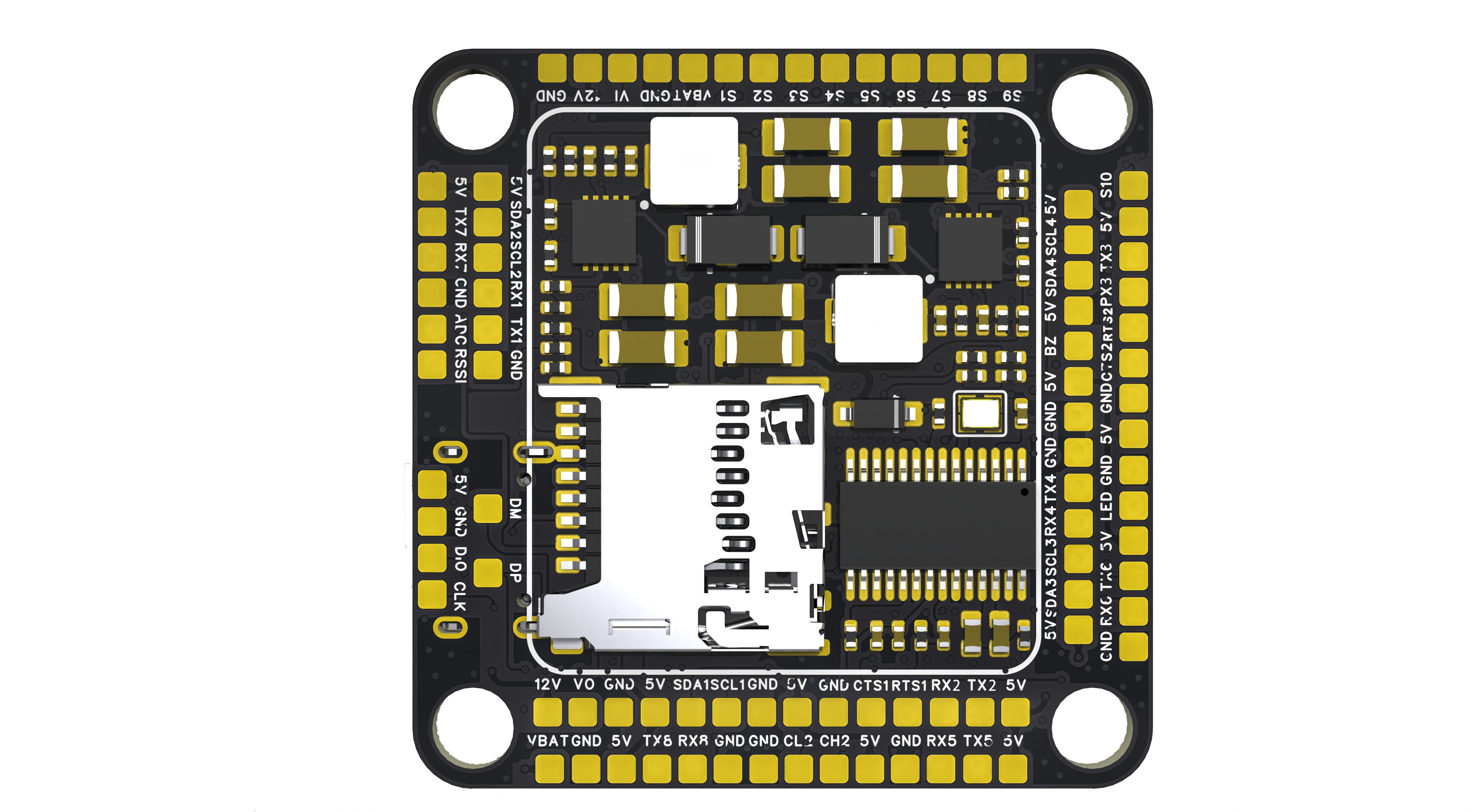
Functional interfaces
include: Serial ports: USART1, USART2, USART3, UART4, UART5, USART6, UART7, UART8 . The APM firmware adds synchronization functionality to the USART chip, making it an enhanced version of UART. USART functionality is only used in the APM firmware; other firmware uses UART
. The APM firmware adds USART_RTS and USART_CTS pin functions to USART2 and USART3, allowing connection to ESCs/data transmissions (cross-wiring is required). (This function is used for current limiting, controlling the amount of data sent via the serial port.)
RTS: Used by the MCU to notify the module whether the MCU is ready and whether the module can send information to the MCU. CTS
: Used by the module to notify the MCU whether the module is ready and whether the MCU can send information to the module
. I2C: I2C1, I2C2, I2C3, I2C4. I2C1 connects to the internal magnetic compass, but has solder pads for future connection.
PWM: S1-S10, plus an LED strip S11.
CAN bus: CAN1, CAN2. The CAN bus is an interface for connecting peripherals to the CAN bus under the APM firmware. Commonly used for connecting GPS devices, RTk devices, and galvanometers to the CAN bus, it can also be used as an expansion module for the CAN bus. This expansion module can connect serial devices, I2C devices, and SPI devices.
Analog image transmission: VI image input interface (connects to the camera signal line), VO image output port (connects to the image transmission signal line).
Analog input: CURR (for galvanometer analog signal input), RSSI (for signal strength input, generally used for receiver signal strength interface), and one unused ADC pin that can be configured to connect to an analog airspeed meter (3.3V analog signal, cannot be connected to 6.6V).
Debug interfaces: SWDIO, SWCLK, USB_DM_USB_DP.
[Rendering ,
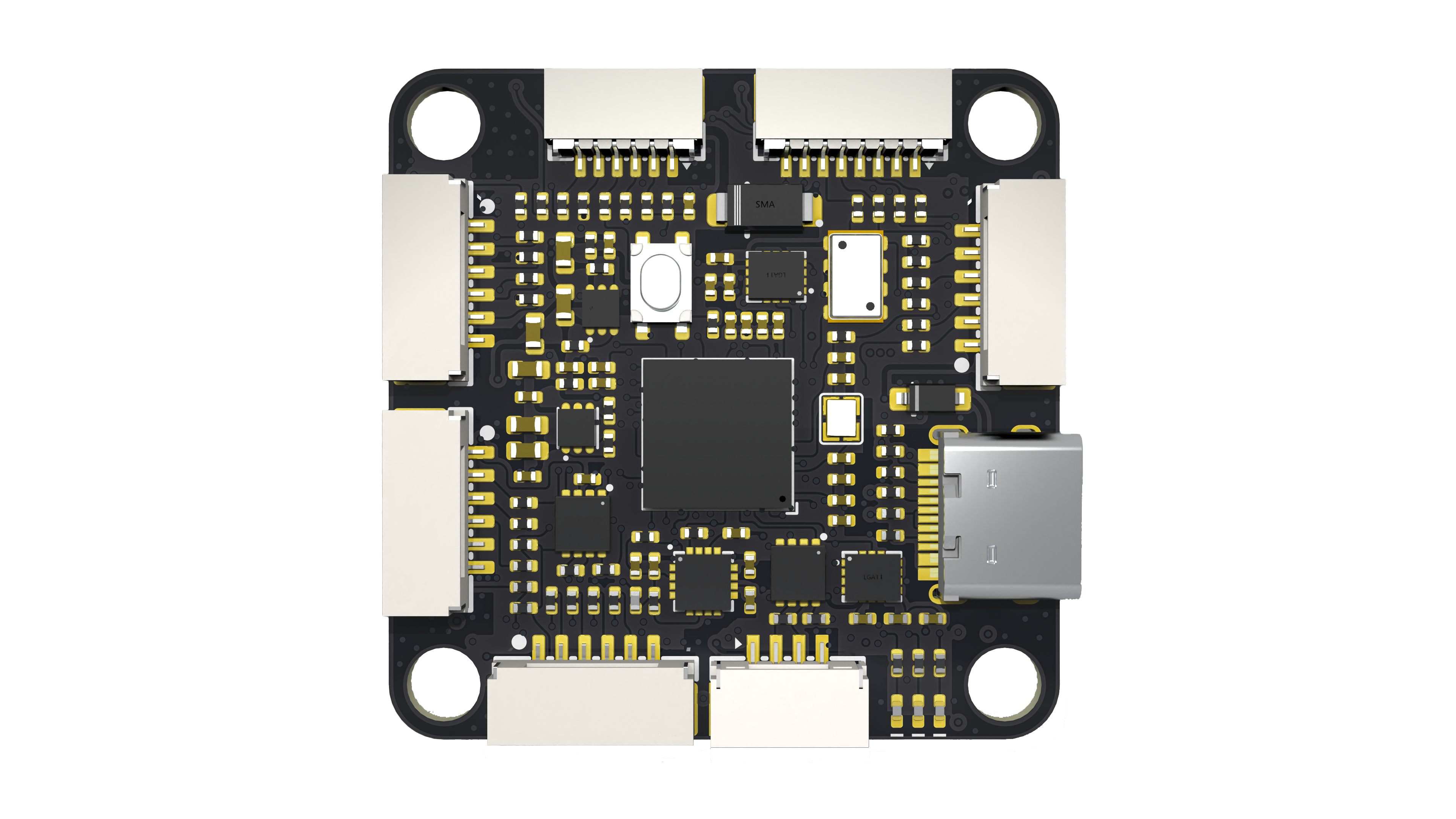
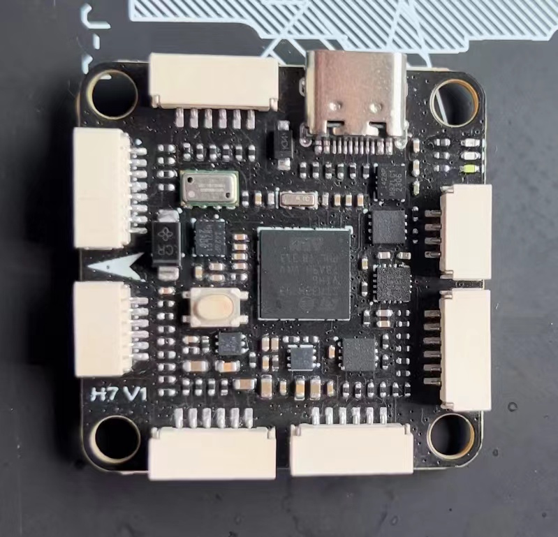
soldering effect,
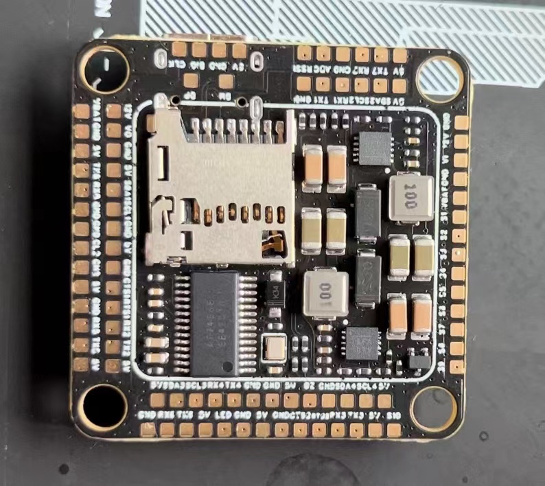
wiring diagram

] [For inquiries or commercial inquiries , please contact via

WeChat. Open source is not easy, thank you for your support. ]
SULILGH743_DX Flight Controller Data.rar
Indoor APM Firmware Manual Flight Video.mp4
PDF_SULILGH743_DX_STM32H743VIH6 flight controller.zip
Altium_SULILGH743_DX_STM32H743VIH6 flight controller.zip
PADS_SULILGH743_DX_STM32H743VIH6 flight controller.zip
BOM_SULILGH743_DX_STM32H743VIH6 flight controller.xlsx
91749
Traffic light module
Traffic light module
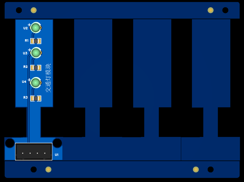
This is a simple traffic light module. A microcontroller outputs a high-level signal to control three individual LEDs. The circuit diagram is shown below.
Each LED has a current-limiting resistor.
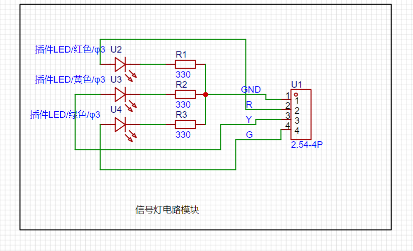
The actual circuit diagram is shown below.
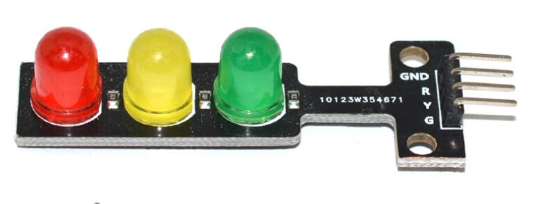
The PCB uses panelization because each LED is a bit small.
Actual verification is as follows:


PDF_Traffic Light Module.zip
Altium_Traffic Light Module.zip
PADS_Traffic Light Module.zip
BOM_12.Traffic Light Module.xlsx
91750
Car steering wheel multifunction buttons
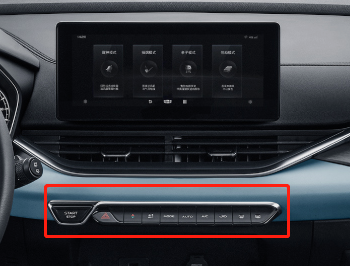
Since I recently installed a Dingwei car infotainment system on my old Peugeot, but it doesn't have a multi-function steering wheel button, and Bluetooth buttons on Taobao are too expensive and don't look good, I made my own multi-function button that is compatible with most Android car infotainment systems.
Preface:
I recently installed a Dingwei car infotainment system on my old Peugeot, but it lacks multi-function steering wheel buttons and physical buttons. Controlling music while driving is difficult due to multiple inputs. Bluetooth buttons on Taobao are too expensive and unattractive, so I created a custom multi-function button compatible with most Android car infotainment systems.
The principle
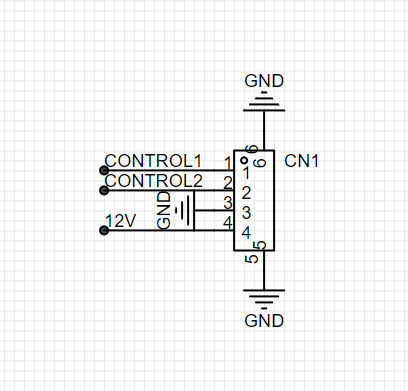
is simple: the car infotainment system detects the resistance between two control wires, with different resistance values corresponding to different button functions (this is common for most Android car infotainment systems). Therefore, you only need to connect different switches to different resistors. For
the components,
I used a non-HiFi tactile switch, and then, inspired by a mechanical keyboard switch, I used one. I personally prefer tactile switches. The solder pads are compatible with most switches (I think), and it uses soldering (if hot-swappable is required, please modify accordingly and pay attention to the spacing). The keycaps are 18x23 and 18x18.
The outer
shell is 3D printed, giving it a piano key look, which I think is quite nice (note the temperature inside the car and the material's heat distortion temperature). It's directly glued under the car infotainment screen; I don't have a physical prototype yet.

~~I wanted to make something like this, but since I'm not aiming for mass production, I can forget about it...
This is
because the circuit board was obtained free, so the 8 buttons were split into two. However, the board can theoretically be expanded infinitely. The cascade pad in the image below is the expansion port, which is essentially two square control learning lines +12V. Simply connect the corresponding pads on the board you want to connect to. It
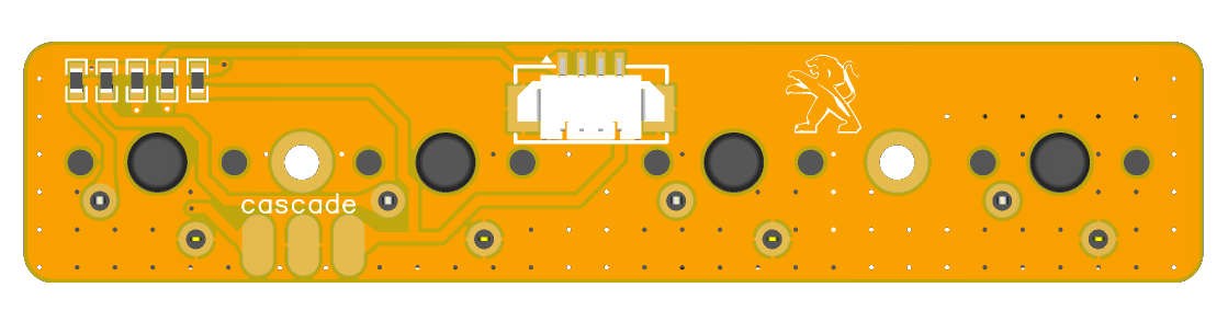
doesn't inherently need a 12V power supply; however, considering visibility while driving at night, a 12V ILL (the car's parking light detection line) was added. Turning on the headlights will activate the backlight (backlight brightness is selectable), controlled by the R5 resistor value.

Wiring instructions:
CONTROL1-----> connect to square control learning line 1;
CONTROL2-----> connect to square control learning line 2
; GND------------> ground wire
12V-------------> connect to parking light detection line (ILL).
The board tests and functions normally. It works well for blind operation, eliminating the need to stare at the screen while driving.
Please drive safely!
Video_20230610162731.mp4
PDF_Car Steering Wheel Multifunction Buttons.zip
Altium_Car Steering Wheel Multifunction Buttons.zip
PADS_Car Steering Wheel Multifunction Buttons.zip
BOM_Car Steering Wheel Multifunction Buttons.xlsx
91751
electronic


 京公网安备 11010802033920号

 10121750-0532243LF


