Project Overview:
This project is a charging management module with a wide input voltage range, capable of charging dual-cell and triple-cell lithium batteries in series. In
dual-cell lithium battery mode, it is compatible with 5V and 9V adapters.
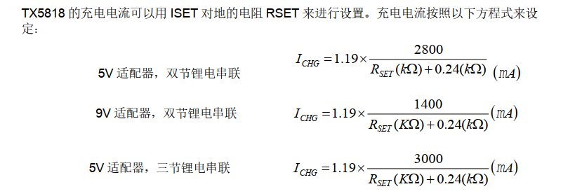
With a 5V supply, it provides boost charging for both dual-cell and triple-cell lithium batteries. With a 9V supply, it provides linear buck charging for dual-cell lithium batteries. The charging current can be set via an external resistor RSET.
Project Features
: Built-in OVP
26V input withstand voltage, excellent surge protection
Automatically identifies whether the connected charger is 5V or 9V in dual-cell lithium battery mode
Supports adapter current adaptive function
Minimal external components, supports 2.2μH inductor
15mA battery full charge cut-off current
±1% battery full charge voltage accuracy
Maximum battery charging current up to 1.55A
Charging efficiency up to 88%
Adjustable charging constant current value
Trickle, constant current, and constant voltage charging modes
Charging status indication
NTC battery high and low temperature protection
Frequency dithering design for ultra-low EMI
Built-in undervoltage protection and overtemperature protection
Lead-free and halogen-free package, QFN3×3-16
Project Parameters
: VIN: 5/9V, VOUT: 2-3 series, Imax: 1.55A
Built-in: TX5818
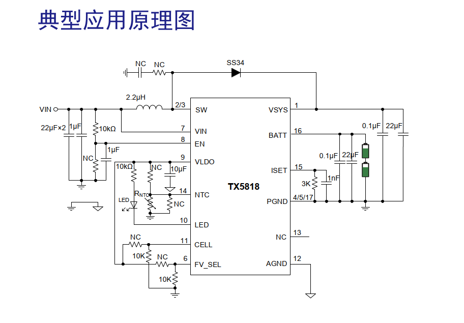
Principle Analysis (Hardware Description)


Charging Current Setting
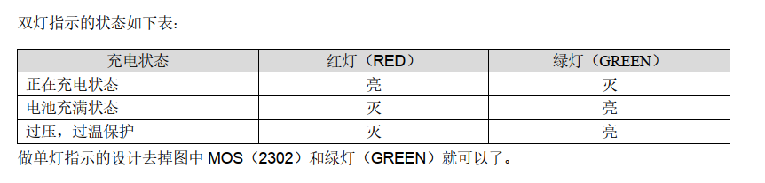
Indicator Status
Output Battery Quantity Setting
Charging Cell Selection Pin is 11. The CELL pin is left floating or connected to a 10kΩ resistor to ground for dual-cell charging mode. Connecting a 10kΩ resistor to the LDO enables triple-cell charging mode.
Single Cell Rated Voltage Setting
Battery Full Charge Voltage Selection Pin is 6. The FV_SEL pin is left floating or connected to a 10kΩ resistor to ground. Dual-cell full charge voltage is 8.4V, triple-cell full charge voltage is 12.6V. Connecting a 10kΩ resistor to the LDO enables dual-cell full charge voltage of 8.7V, triple-cell full charge voltage of 13.05V.
Battery Temperature Monitoring
To prevent damage to the battery from excessively high or low temperatures, the TX5818 integrates a battery temperature monitoring circuit. Battery temperature monitoring is achieved by monitoring the voltage at the NTC pin. The NTC pin voltage is determined by the NTC thermistor inside the battery and a resistor divider network, as shown in a typical application circuit.
If battery temperature monitoring is not required, the NTC pin can be left floating. After one charging cycle, the TX5818 will turn off the charging display. During this period, the battery may experience a decrease in charge due to natural discharge.
To prevent the battery from automatically depleting while connected to the adapter, a new charging cycle will automatically begin when the battery voltage drops to the automatic charging threshold (typically 8.2V for dual-cell lithium batteries and 12.3V for triple-cell lithium batteries). LAYOUT Notes: 1. The current from VIN through the inductor and diode to pin 1 (VSYS) of the chip carries a large current. The traces in this loop should be as thick and short as possible, and the inductor and diode should be placed close to the chip. 2. A 0.1μF and a 22μF surface-mount capacitor must be placed at the boost output pin (VSYS). The 22μF capacitor should be placed with one end close to the VSYS pin and the other end close to the chip's ground (pins 4/5) (see screenshot). A 1206 package is recommended for the 22μF capacitor. 3. A 1μF and two 22μF surface-mount capacitors need to be placed at the VIN terminal. These three capacitors should have one end close to the chip pin (pin 7) and the other end close to the chip's ground (pins 4/5). 4. The LDO external capacitor (10μF) should have the shortest possible path from the LDO (pin 9) to AGND (pin 12). 5. The copper trace from the chip's BATT pin to the positive battery terminal needs to carry a large current; this section should be as short and thick as possible. A 0.1μF and a 22μF surface-mount capacitor need to be placed from BATT (pin 16) to ground. One end of the capacitor should be close to the pin (pin 16), and the other end should form a good loop with the chip's ground. 6. Reserve an RC circuit to ground at the SW terminal (pins 2/3). (Generally, no component needs to be placed; it can be added if required during certification).


 京公网安备 11010802033920号

 1200RGH100222HB


