The main function used is the ADC (Analog-to-Digital Converter), also known as an A/D converter or simply ADC, which is an electronic component that converts analog signals into digital signals. A typical ADC converts an input voltage signal into an output digital signal. Since digital signals themselves do not have practical meaning, only representing a relative magnitude, any ADC needs a reference analog quantity as a conversion standard. A common reference standard is the largest convertible signal size. The output digital quantity represents the magnitude of the input signal relative to the reference signal. The CW32F030 integrates a 12-bit precision, 1M SPS (Maximum SPS) successive approximation ADC (SAR ADC), capable of converting up to 16 analog signals into digital signals. Most signals in the real world are analog, such as light, electricity, sound, and image signals, all of which must be converted into digital signals by an ADC before being digitized by the MCU.
In terms of software design, the ADC module of the CW32F030 microcontroller is the core for implementing voltage and current measurement. The ADC module has multiple conversion modes, supporting single conversion, multiple conversions, and continuous conversion, and also features sequential scan conversion and discontinuous sequence conversion. The basic parameters of the ADC include resolution, sampling rate, and sampling range. In software design, the ADC channels need to be configured, and corresponding initialization code is written to complete voltage and current sampling and display the results on the digital tube. For voltage and current measurement accuracy, a mean filtering algorithm can be used to reduce data fluctuations and improve the stability of measurement results. The advanced tutorial for the CW32 digital voltmeter and ammeter software introduces how to perform mean filtering on the real-time displayed voltage and current values to eliminate fluctuations in the original data. Furthermore, to improve measurement accuracy, the voltmeter and ammeter can be calibrated. Calibration is the operation of compensating for instrument system errors by measuring the deviation of a standard. Experiment Nine introduces the implementation method of a digital voltmeter and ammeter with calibration function, including the concept of calibration, explanation of important code, and calibration operation methods.
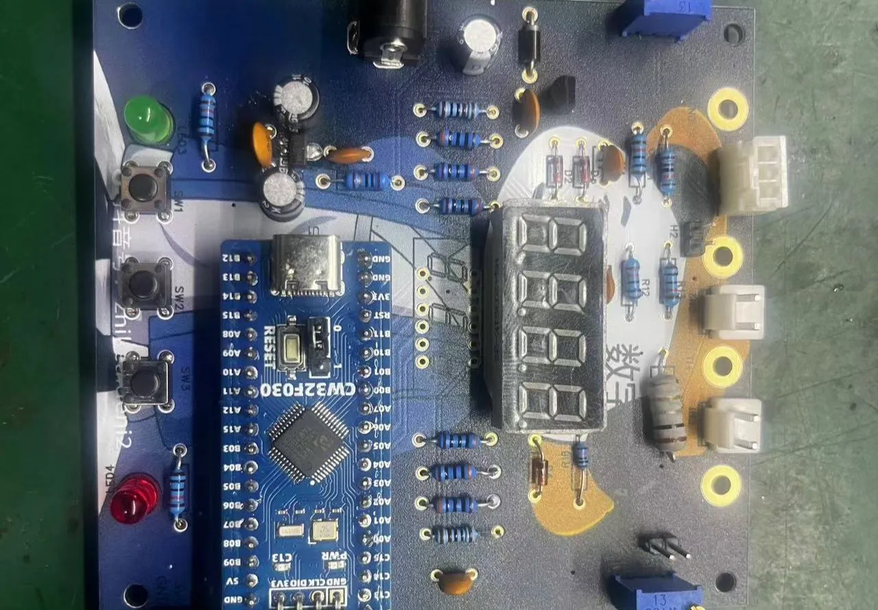
Principle Analysis (Hardware Description)
1. Voltage Sampling
This project uses a voltage divider circuit to achieve high voltage acquisition. It is designed to acquire a voltage of 100V, and the current configuration is to acquire a voltage of 0-30V. The voltage divider resistors in this project are designed to be 220K+10K, therefore the voltage division ratio is 22:1 (ADC_IN11).
1.1 Voltage Sampling Voltage Divider Resistor Selection
Design: The maximum value of the measured voltage is 30V for safety reasons (the actual maximum display value can be 99.9V or 100V); the ADC reference voltage is 1.5V in this project, which can be configured through the program; to reduce the power consumption of the sampling circuit, the low-side resistor (R7) is usually selected as 10K based on experience; then the high-side resistance of the voltage divider resistor can be calculated using the above parameters: Calculate the required voltage division ratio: i.e., ADC reference voltage: design input voltage, which can be calculated using known parameters as 1.5V/30V=0.05; Calculate the high-side resistance: i.e., low-side resistance/voltage division ratio, which can be calculated using known parameters as 10K/0.05=200K. Select a standard resistor: Choose a resistor with a value slightly higher than the calculated value, which is 200K. We typically choose E24 series resistors; therefore, in this project, we choose 220K, which is greater than 200K and closest to the calculated value. If, in actual use, the voltage to be measured is lower than 2/3 of the module's design voltage (66V), the voltage divider resistor can be replaced and the program modified to improve measurement accuracy. The following example illustrates this: Assuming the measured voltage is no higher than 24V and other parameters remain unchanged, calculations show 1.5V/24V = 0.0625, 10K/0.0625 = 160K. 160K is a standard E24 resistor and can be directly selected, or a higher value 180K can be chosen with some redundancy.
If, in actual use, the voltage to be measured is higher than the module's 99V design voltage, a different resistor can be selected. To achieve a wider voltage measurement range, one can choose to replace the voltage divider resistor or modify the reference voltage. The following example illustrates this: Assuming the measured voltage is 160V, the solution is to increase the voltage reference to expand the range. Given that the voltage division ratio of the selected resistor is 0.0145, we can calculate 160V * 0.0145 = 2.32V using the formula. Therefore, we can choose a 2.5V voltage reference to increase the range (increasing the range will reduce accuracy). Considering the potential fluctuations in the measured power supply, a 10nF filter capacitor is connected in parallel with the low-side voltage divider resistor to improve measurement stability.
1.2 Voltage Sampling Diode Clamping Ensures MCU Safety.
In designing this project, I added an additional 1N4148 (D1, etc.) as a clamping diode to the sampling circuit. This is to avoid damage to the chip pins due to incorrect voltage input during learning and debugging. Diode clamping is an important electronic circuit design technique. Its main function is to protect the circuit by limiting the voltage amplitude, preventing damage or malfunction caused by excessively large or small signals.
In circuit design, clamping refers to limiting voltage. Diode clamping specifically refers to the technique of using a diode to limit the potential at a point in a circuit.
Diode clamping primarily utilizes the unidirectional conductivity of a diode. When the voltage across the positive terminal of the diode is greater than the voltage across the negative terminal and the diode is turned on, the voltage across the diode is limited to its voltage drop across the diode, typically around 0.7V for a silicon diode.
The clamping process involves forcibly pulling the clamped potential towards the reference terminal through the diode's clamping action, thus limiting the potential. Clamping does not change the waveform of the original signal; it only raises or lowers the reference potential. Depending on the diode connection method, clamping circuits can be divided into positive clamping circuits and negative clamping circuits. This project only designs positive clamping.
Positive clamping circuit: When the positive terminal of the diode is grounded, it is a positive clamping circuit. During the positive half-cycle, the diode is cut off; during the negative half-cycle, the diode is turned on, and the capacitor is charged to a certain voltage, limiting the output voltage within a certain range.
Negative clamping circuit: When the negative terminal of the diode is grounded, it is a negative clamping circuit. The working principle is the opposite of the forward clamping circuit.
Adding a voltage sampling circuit enables range switching.
In this project, an additional voltage sampling circuit was added, so we can discuss the significance of range switching for improving measurement accuracy. Multimeters often have multiple range settings to achieve more accurate measurements. By adjusting different ranges, the optimal measurement accuracy of the measured point within the corresponding range can be obtained.
This project requires a combination of hardware and software to achieve this function. When we first use the ADC_IN11 channel mentioned earlier to measure voltages below 30V, if the measured voltage is within 0~3V, then we use the ADC_IN9 channel for measurement. At this time, due to the reduced voltage division ratio, the measurement accuracy is greatly improved.
There are many ways to implement range switching, and the development board design provides more design possibilities.
The components labeled T_V and T_GND are the 2mm banana plug interfaces on the development board, used to connect the multimeter probes. The probes of a multimeter or a high-precision benchtop digital multimeter can be inserted to verify the accuracy of the development board's measurements. A 2mm banana-tip multimeter probe can also be inserted to replace the CH1 port for handheld measurements.
The VP pin is the development board's power supply pin and should not be connected when using the DC port. When not using the DC port for power supply and the measured value is greater than 5V but less than 30V, the power supply under test can be connected, or it can be powered independently.
Considering that users may not be able to easily build external circuits for testing and debugging when learning the corresponding circuit measurement principles, and adhering to the principle of ease of development of the development board, auxiliary circuits for simulating voltage measurement, measurement calibration, and measurement calibration are specially set up. No external voltage is required for CH1. Use the multi-turn adjustable potentiometer (RP1) to divide the development board's power supply voltage and connect it to the +V network through the development board's internal circuitry. Note that H2 needs to be shorted at this time; a jumper cap is sufficient, and a long-handled jumper cap is recommended. Do not short H2 if this function is not used.
Software code:
See the attached compressed package "CW32 Voltage and Current Meter Code" for the software code.
Notes:
Here I mainly write about some problems I encountered when burning the software:
Refer to the official documentation and set the compiler to
CMSIS version 5. In the settings page below, remove CMSIS version 6.1.0 and install version 5.6. I haven't tried other versions, but versions lower than 5.4 definitely won't work (I don't know why it shows version 5.4 on this screen, but it's actually only 5.1.2. Now I've installed version 5.6, which is actually 5.3, and it compiles normally, but I don't know why).
Downloading experiments 7, 8, and 9 will report the error shown in the image below because the default chip selection is incorrect. Correct it.
When soldering the socket headers, you can first plug the microcontroller into two sockets and solder them together. This makes it easier to control the spacing. When I soldered mine, I soldered them separately, and finally plugged the microcontroller in with a bit of force; I even had to wiggle the pins to get it in.
For power supply, you can buy 9V dry batteries and a 9VDC adapter cable from Uxin. They should cost around 2.5 yuan. Battery power is definitely more stable than cheap power adapters.
Before safely powering on, use a multimeter in buzzer mode to check for short circuits between VCC and GND. There shouldn't be any major problems. For
ammeter connection, you can connect the ammeter in series into the test system.


 京公网安备 11010802033920号

 ZMM11
ZMM11


