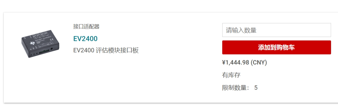
 , fortunately, TI has released the schematic diagram for the EV2400, allowing us to purchase a relatively inexpensive one on Taobao/Xianyu. Alternatively, if you don't want to be ripped off or enjoy tinkering, building your own is a good option. This project provides a verified, well-protected, cost-effective, and aesthetically pleasing DIY EV2400 solution.
 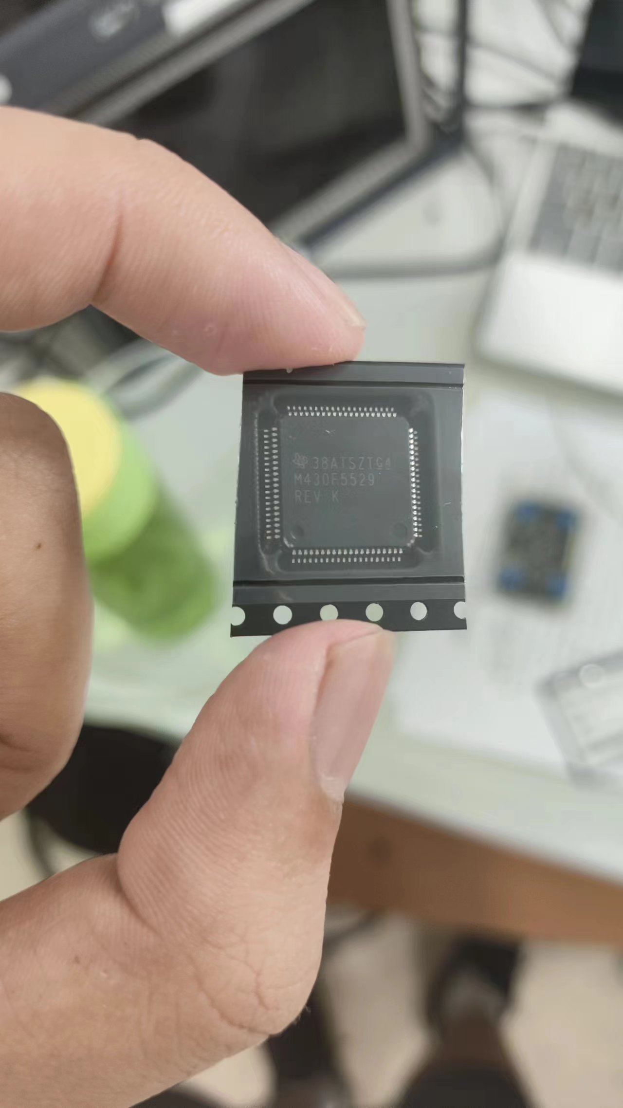 (Note: Some people online have also found that the F5528 (average price around 10 yuan) can be used as a substitute, and there are related solutions. However, I have verified this myself. I bought four chips from different stores, and they either didn't have the core voltage, the crystal oscillator didn't oscillate, or they could only be flashed but couldn't run. There were too many bad products. I spent 40 or 50 yuan on chips but didn't get a single usable one. It's better to just go for the 5529; at least genuine ones are easier to find.) (I'm begging for a reliable source so I can finally put a perfect end to this board that I've been working on for two weeks.)
 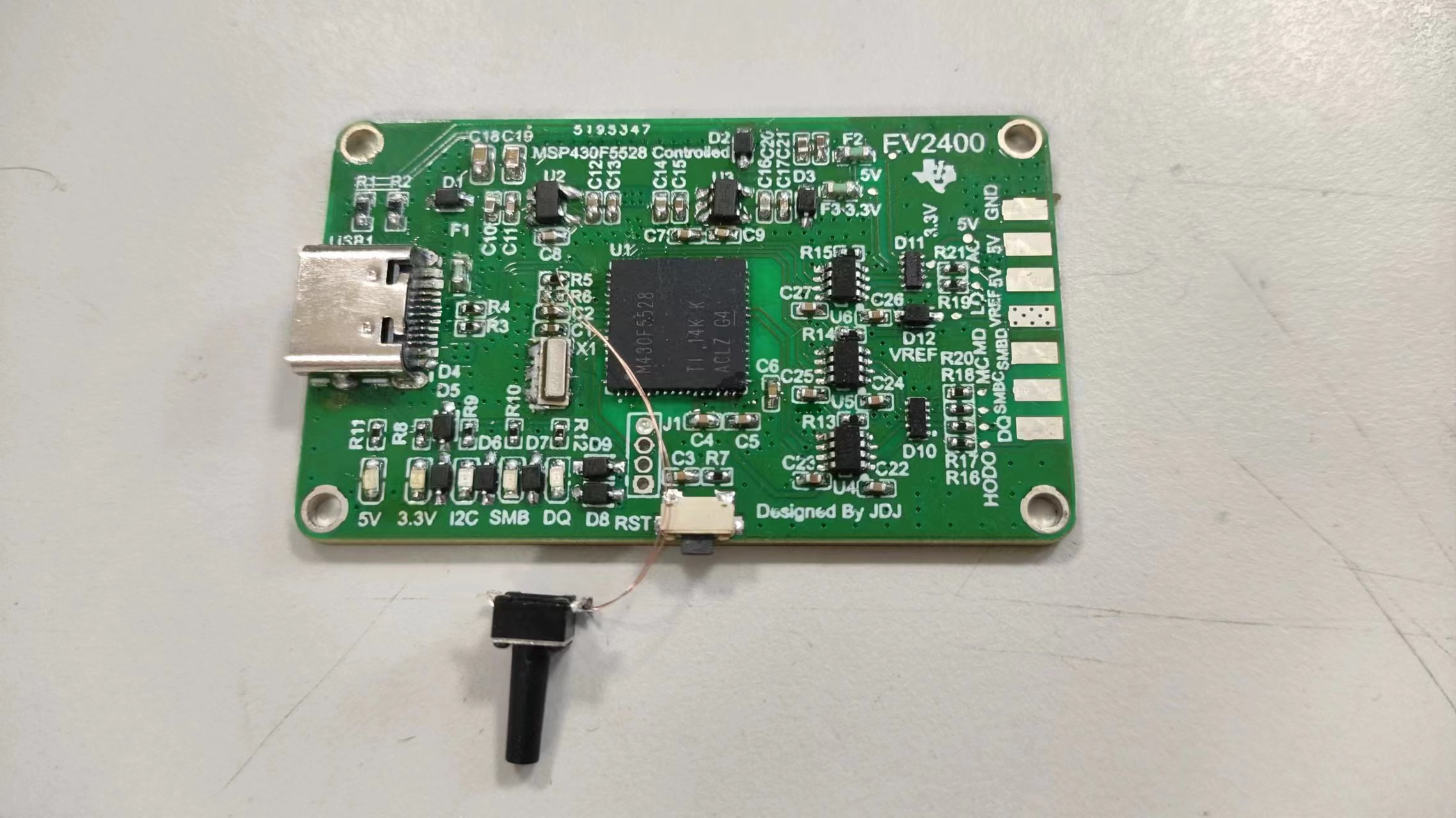 substandard chips in the market. The reasons are explained in the open-source link. TI's official solution uses an adjustable linear regulator in conjunction with a Renesas digital potentiometer to achieve an adjustable reference level. As is well known, these are less common chips, and those sold on Taobao or other reputable platforms are unreliable, while those available here are expensive. Therefore, the adjustable voltage reference level is omitted, leaving only a reference level input pin. Users can short this pin with a jumper cap to determine the communication reference level.
 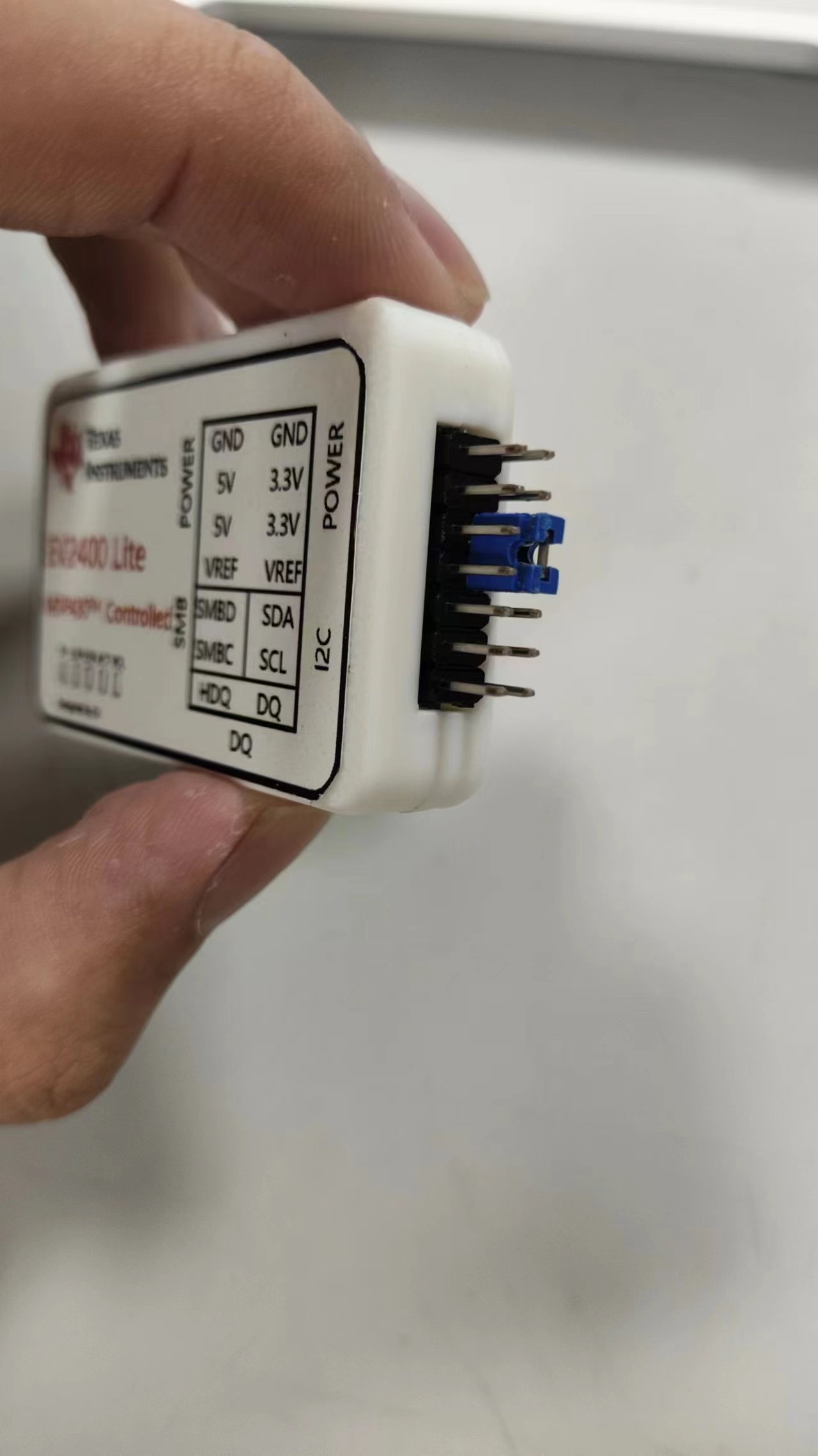 (However, it's worth noting that some sources I consulted (unofficial sources) stated that non-adjustable reference levels (such as the fixed 3.3V reference level used in most lightweight EV2400s on the market) might damage the chip being debugged. However, in my humble opinion, TI, as one of the world's leading analog chip design and manufacturing companies, would certainly consider various application environments. Furthermore, the internal block diagrams provided by TI (using the BQ4050 as an early representative) show that the chip's data interface uses a logic gate buffer circuit between the internal CPU (as shown in the figure).
 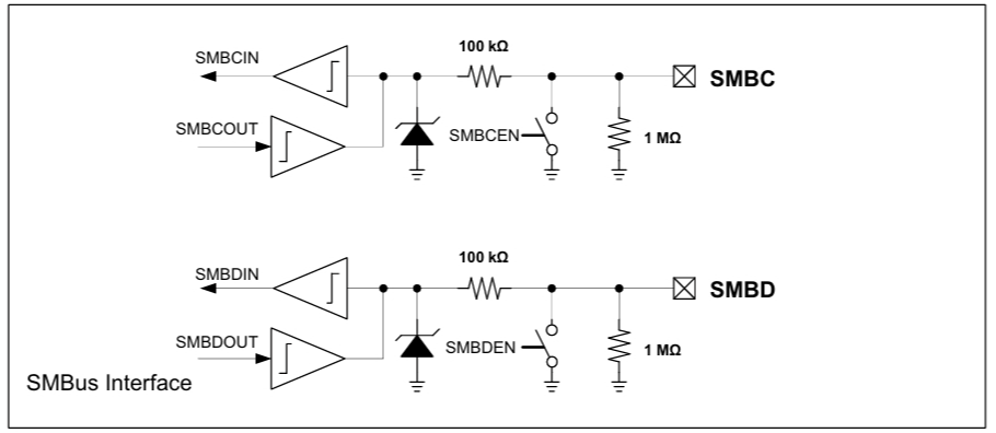 In many designs, the MCU with a 3.3V reference level communicates directly with the battery protection chip, and I haven't seen any chip damage reported. Moreover, in section 6.3 of the BQ4050 datasheet, the maximum withstand voltage for the SMC and SMD interfaces is 26V (as shown in the figure).
 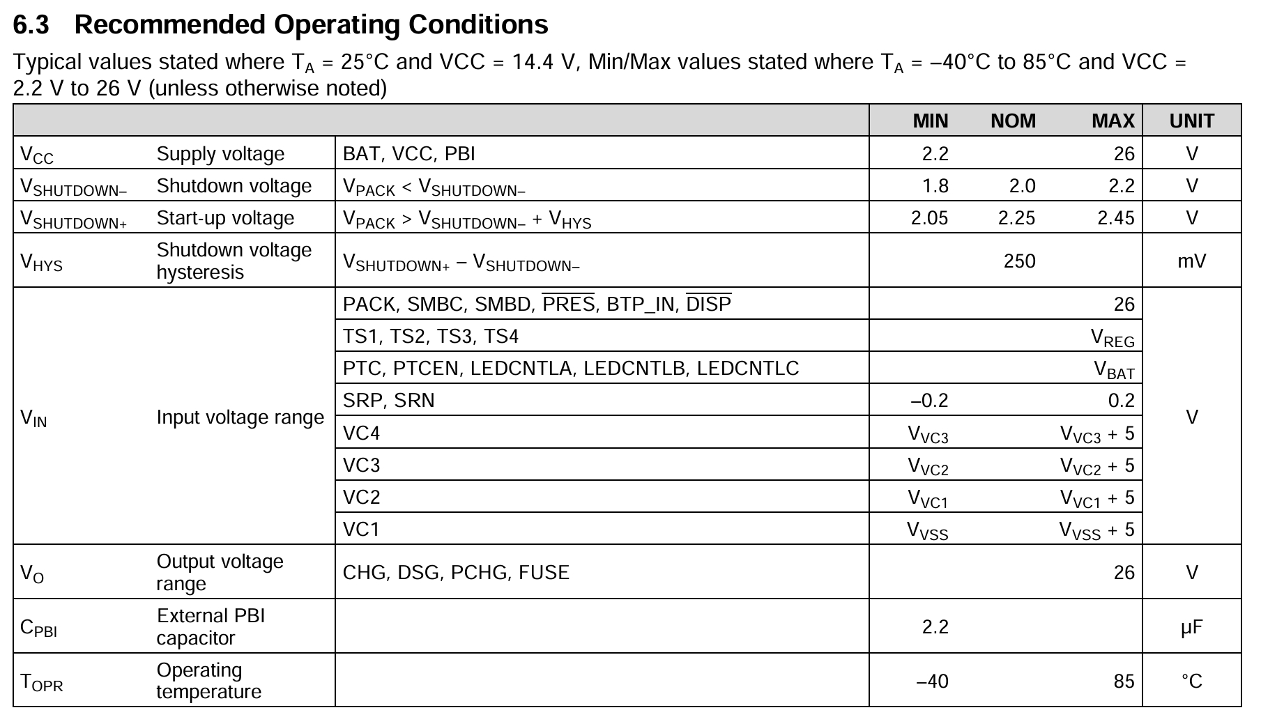 Meanwhile, another TI... ) The BQ40Z80 battery fuel gauge and protection chip integrates a lightweight EV2400 on its EVM. The official schematic indicates that no level conversion IC is used between its interface and the fuel gauge IC interface; instead, only a few pull-up and pull-down resistors are used (as shown in the figure). Research indicates that the BQ40Z80's internal CPU also uses a 1.8V power supply, suggesting that it has internal level conversion circuitry. (Personally, I believe a 3.3V logic level is perfectly acceptable.) While
 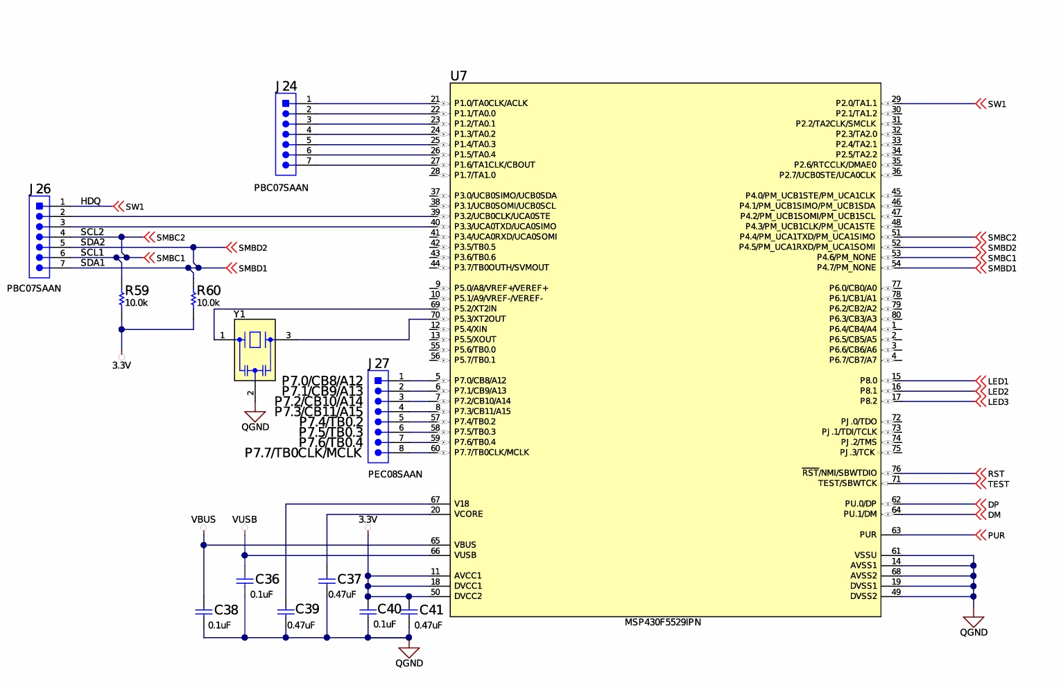 other aspects can be simplified, protection is a crucial function for debuggers. Especially for debuggers that may deal with several or even a dozen battery packs, incorrect connections can cause sparks and damage, potentially even to the computer. Therefore, protection is essential. This solution includes ESD and overcurrent protection. I used a one-time fuse, but it could be replaced with a PTC resettable fuse for even better performance.
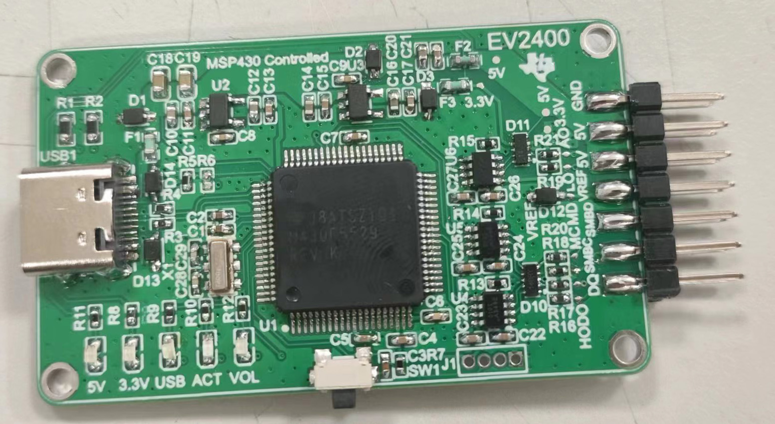
 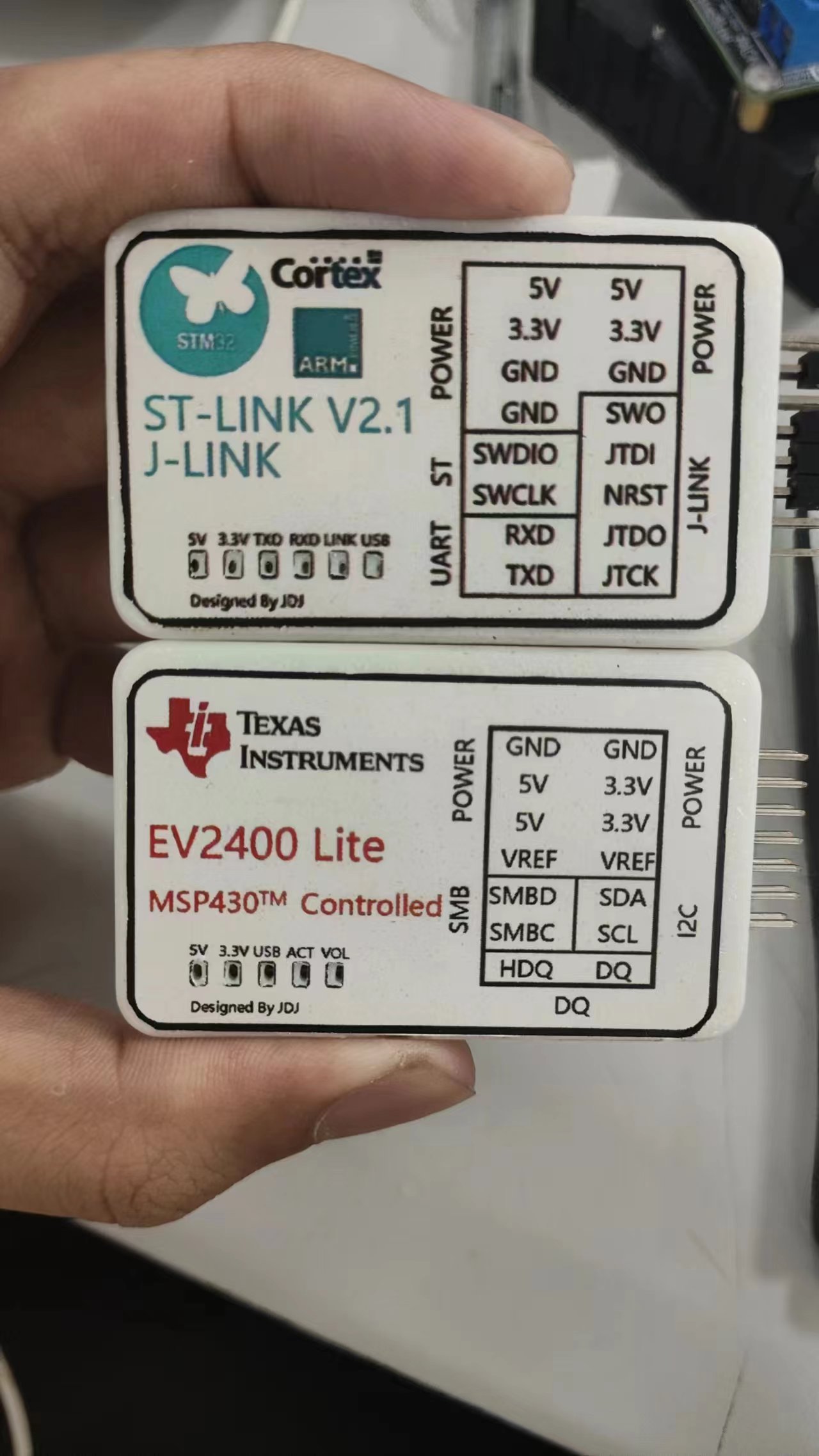 so satisfying!)). The direct-output design means the USB socket, debugger, and debug cable form a straight line, taking up less space. (If you're interested in that ST-Link, here's the link.) ((As an aside, while browsing the MSP manual recently, I found some tutorials from TI on porting STM chip programs to MSP series microcontrollers—stealing ST's talent, haha!) It's true that red and blue are a perfect match! ヾ(≧▽≦*)o)
  Since the 3.3V power supply is mainly used as a reference level this time, an LDO was used instead of a DC-DC converter to provide 3.3V.
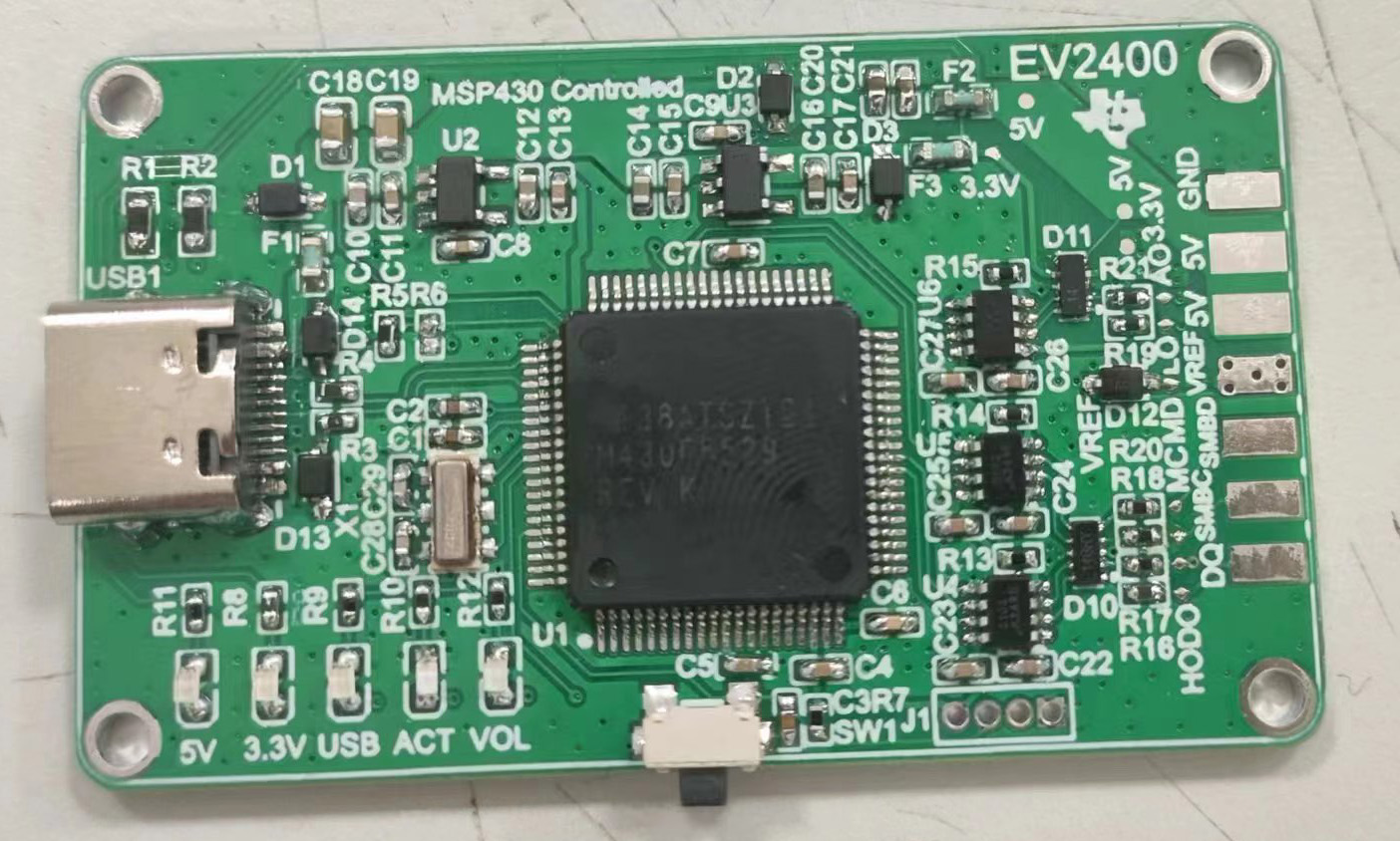
 However, I still need to mention a few things about component purchases:
  Right-click and select "Run as administrator." After installation, a "TI" folder will appear on your C drive. Locate the folder named "EV2400Updater-0.32" inside. The first file in the folder contains our programming program
 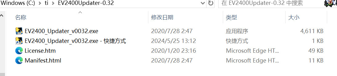 . However, if you directly open it, you'll find that it says it doesn't find the EV2400. This is normal; our EV2400 hasn't been programmed yet. We need to pass parameters to this program so it knows to program a chip that doesn't have a program yet. Right-click the program, select "Create Shortcut," then right-click the created shortcut, click "Properties," type a space after "Target," and then enter "-s." Click "
 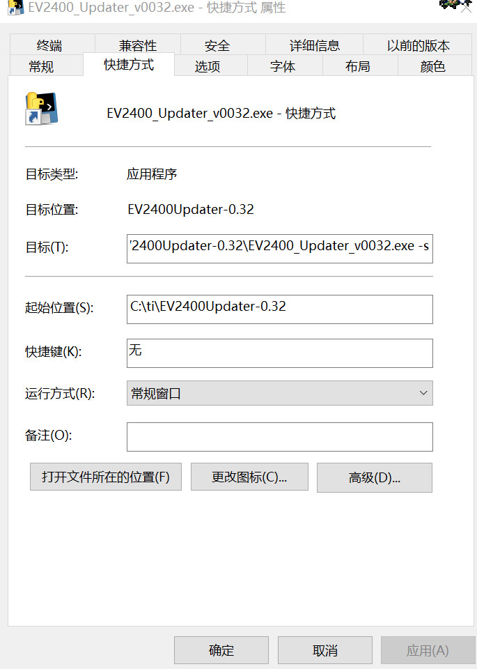 Apply" and then "OK." Now, plug your soldered EV2400 into the computer. Use tweezers to short-circuit the two shorting points shown in the diagram (the two ends of silkscreen R6).
  Then, and this is crucial: while maintaining the short circuit, press the reset button. Release the reset button and immediately remove the tweezers. You should hear a device connection beep on the computer, but no new device will appear in Device Manager, indicating that the computer has recognized the chip. Double-click the shortcut you just created. The software should then indicate that it is erasing, and the computer should emit a device pop-up beep. After the software finishes running, re-plug the chip or press the reset button. The computer should emit another device insertion beep, and all three blue LEDs should light up, indicating that the programming is complete. (Note: If you short-circuit the tweezers to R6 for an extended period, the computer will also emit a device insertion beep and display an unknown device message. This is normal and can be ignored; simply start the process from the beginning. It is not a hardware or chip issue.)
 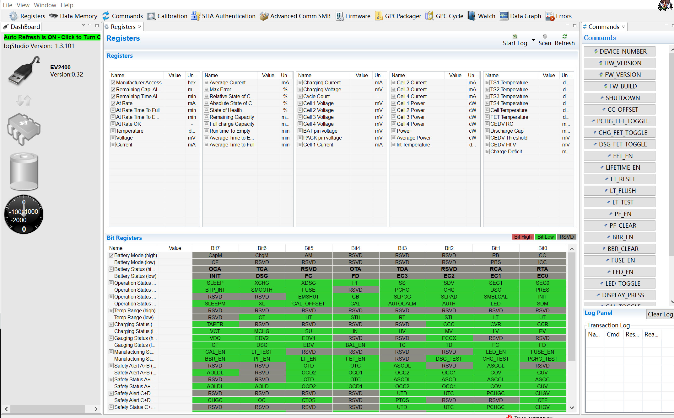 OK, the EV2400-Lite setup is now complete. Go ahead and enjoy unlocking the battery OR the grueling debugging!
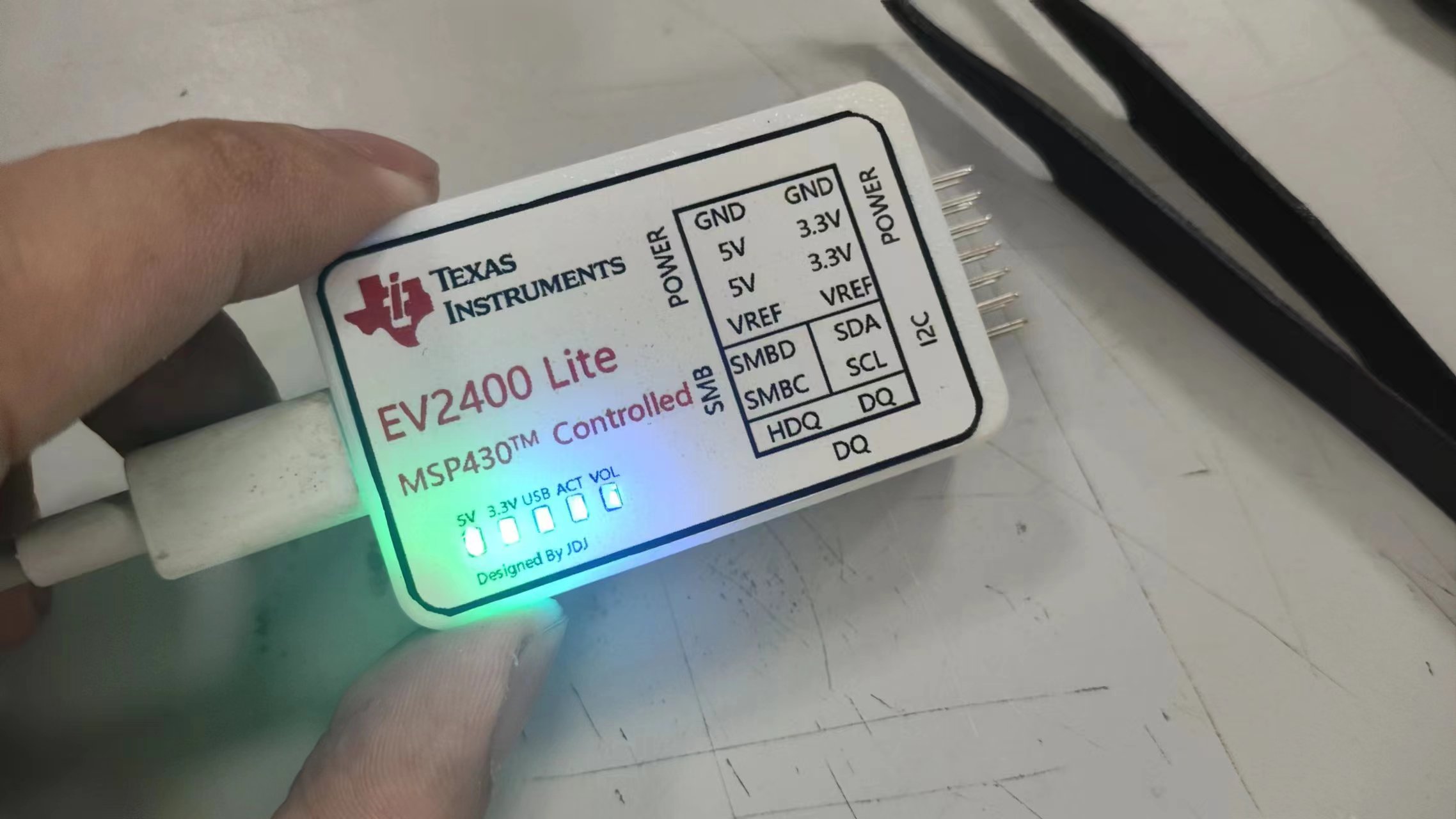 (This light is so bright, haha. A larger current-limiting resistor or a black casing for printing would probably be better.)
All reference designs on this site are sourced from major semiconductor manufacturers or collected online for learning and research. The copyright belongs to the semiconductor manufacturer or the original author. If you believe that the reference design of this site infringes upon your relevant rights and interests, please send us a rights notice. As a neutral platform service provider, we will take measures to delete the relevant content in accordance with relevant laws after receiving the relevant notice from the rights holder. Please send relevant notifications to email: bbs_service@eeworld.com.cn.
It is your responsibility to test the circuit yourself and determine its suitability for you. EEWorld will not be liable for direct, indirect, special, incidental, consequential or punitive damages arising from any cause or anything connected to any reference design used.
Supported by EEWorld Datasheet
EEWorld
subscription
account

EEWorld
service
account

Automotive
development
community

Robot
development
community

About Us Customer Service Contact Information Datasheet Sitemap LatestNews


Room 1530, 15th Floor, Building B,
No.18 Zhongguancun Street,
Haidian District,
Beijing, Postal Code: 100190
China
Telephone: 008610 8235 0740
 京公网安备 11010802033920号

 BD136
BD136


