 Back view:
 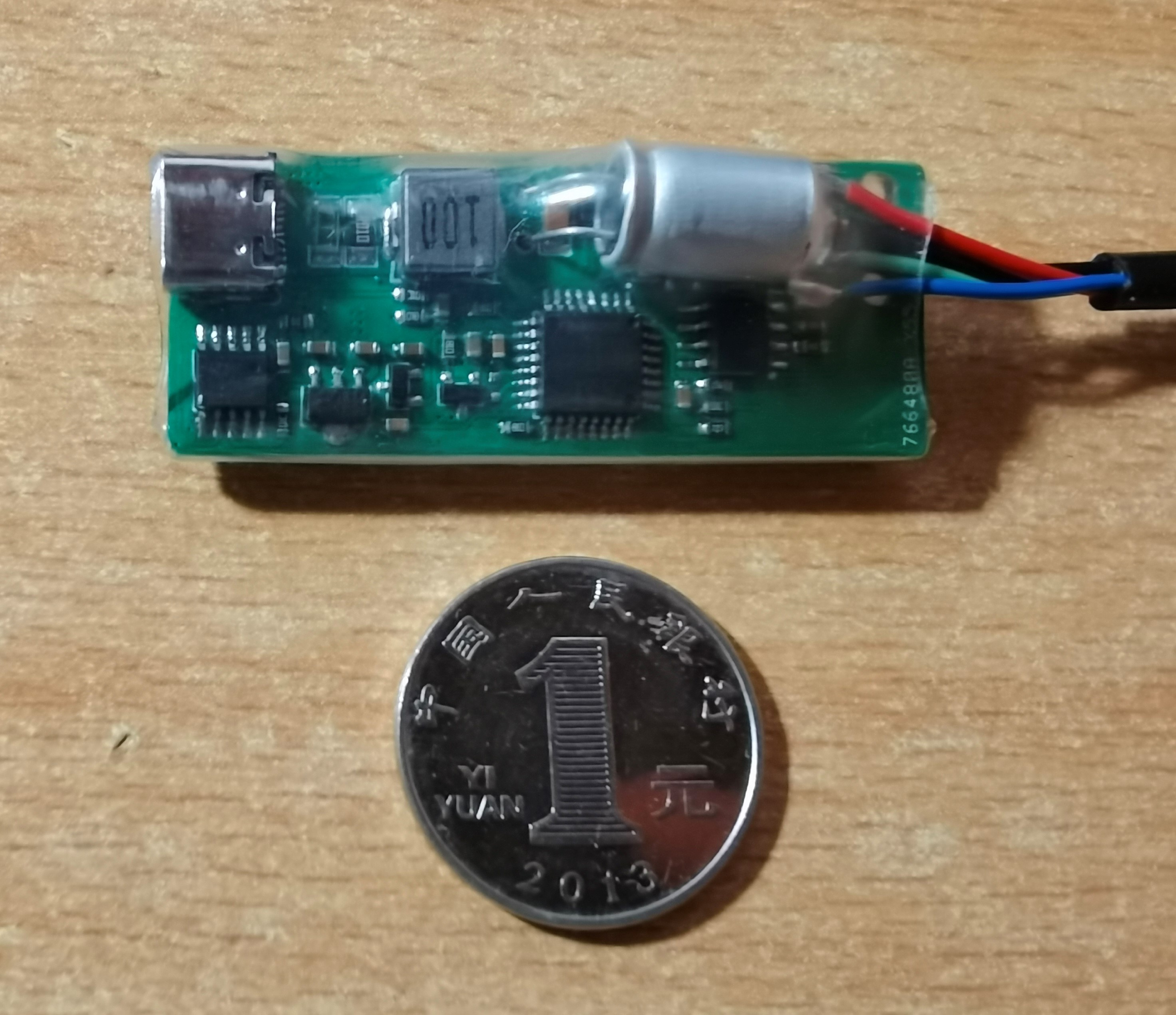 Controller temperature recovery effect. The green line represents the PWM duty cycle, the black line represents the current, the blue line represents the target value (280℃), and the red line represents the actual value (real). During the experiment, the solder joints were continuously melted with the soldering iron. As you can see, the deviation of the target from the real is very small (within 3℃).
 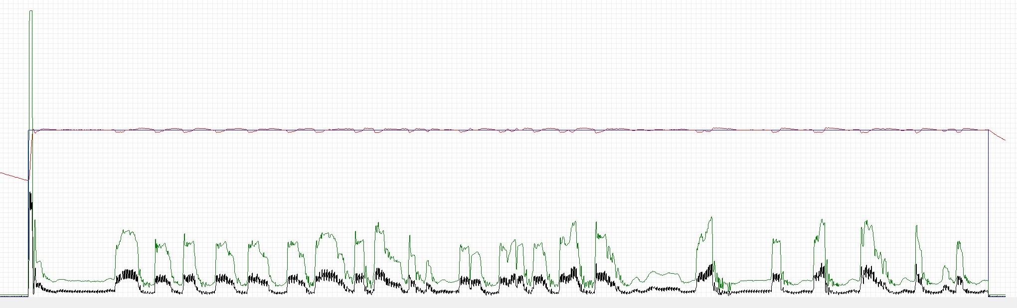 III. How to Replicate
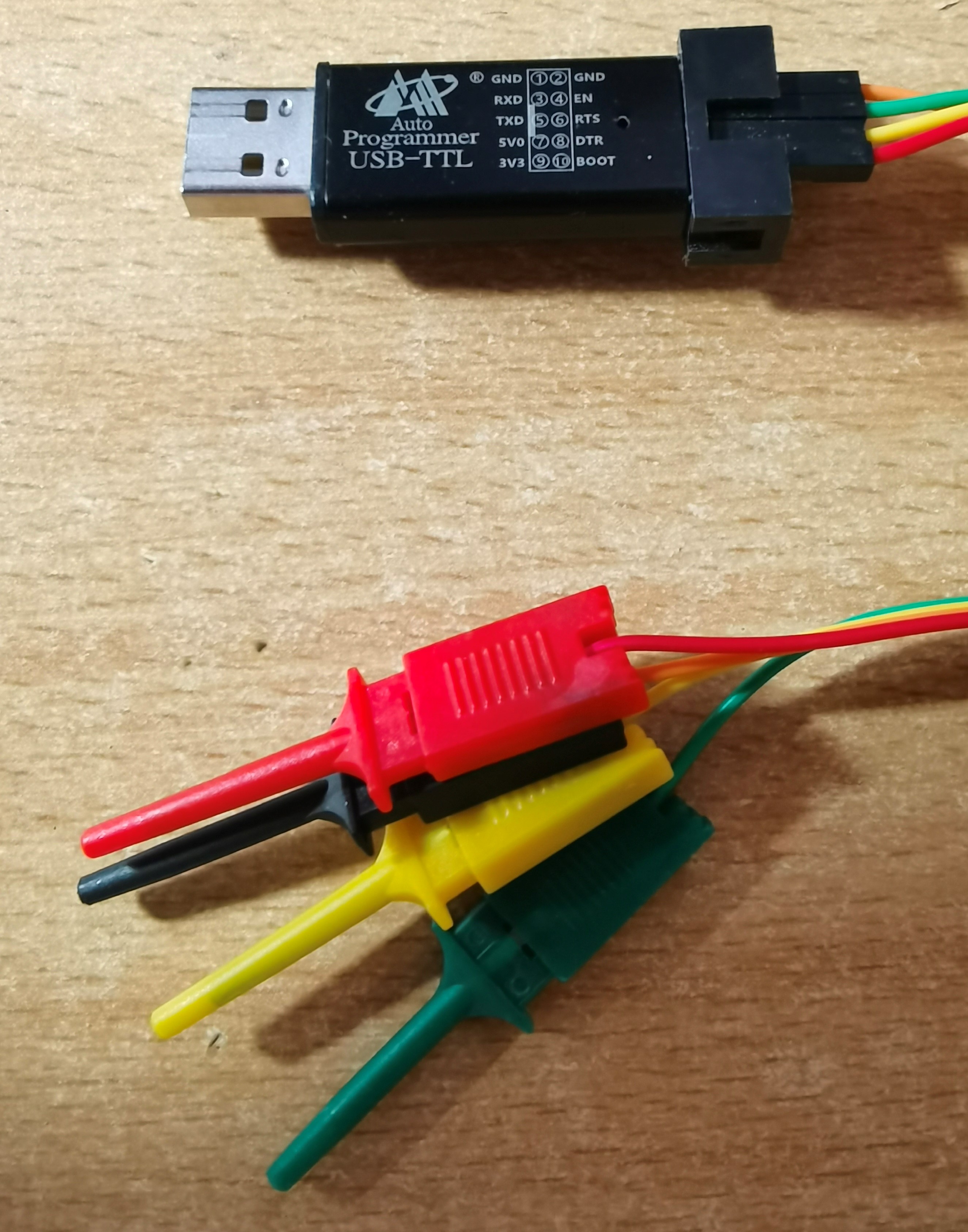
  This project only includes the control board. The soldering iron handle can be purchased on Taobao and Xianyu. Generally, a good quality soldering iron handle can be found for around 30 RMB. Unlike other JBC open-source projects, the control board of this project requires a 4-wire soldering cable. Please note that it is 4-wire. Typical JBC open-source projects use 3-wire cables. The cable can also be purchased on Taobao. The keyword is "soldering station cable". I used a 1.2m long, 40mm outer diameter 4-core cable.
 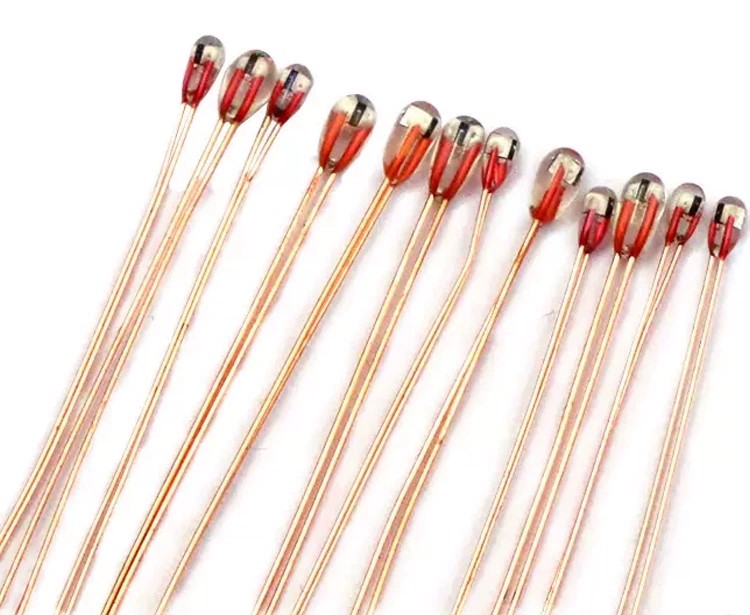 the NTC is placed inside the handle and connected across GND and RT. The NTC is not reversible.
  2. Programming
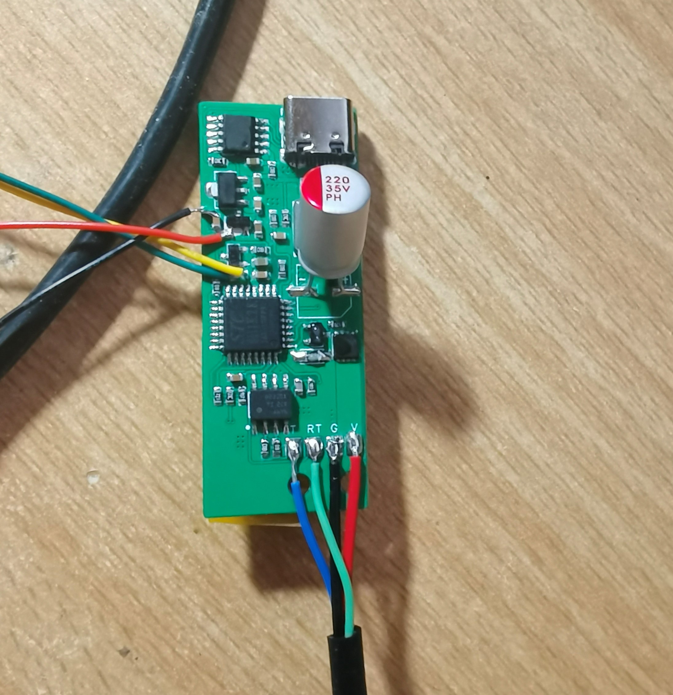
 3. Temperature Control Algorithm
  Using the function relationship shown in the figure above for temperature control has clear advantages. When the error is near 0, the system approximates ordinary PID control. When the error is large, Kp increases while Ki decreases. Increasing Kp allows the system to converge quickly, while decreasing Ki reduces the integral contribution when the error is large, thus suppressing temperature overshoot. Practical testing showed that this control method performs well. The convergence speed is faster than pure PID, and the overshoot is smaller. In this project, the D parameter was directly set to 0.1. I didn't spend too much time on precise parameter tuning, so there is still some room for optimization of the PID parameters. The relationship between Kp, Ki, and error is given below.
  Finally, the MOS used in the project is AP90P03Q, with the same package as the one on the PCB. For some reason, there is no schematic diagram, so it can only be attached.

All reference designs on this site are sourced from major semiconductor manufacturers or collected online for learning and research. The copyright belongs to the semiconductor manufacturer or the original author. If you believe that the reference design of this site infringes upon your relevant rights and interests, please send us a rights notice. As a neutral platform service provider, we will take measures to delete the relevant content in accordance with relevant laws after receiving the relevant notice from the rights holder. Please send relevant notifications to email: bbs_service@eeworld.com.cn.
It is your responsibility to test the circuit yourself and determine its suitability for you. EEWorld will not be liable for direct, indirect, special, incidental, consequential or punitive damages arising from any cause or anything connected to any reference design used.
Supported by EEWorld Datasheet
EEWorld
subscription
account

EEWorld
service
account

Automotive
development
community

Robot
development
community

About Us Customer Service Contact Information Datasheet Sitemap LatestNews


Room 1530, 15th Floor, Building B,
No.18 Zhongguancun Street,
Haidian District,
Beijing, Postal Code: 100190
China
Telephone: 008610 8235 0740
 京公网安备 11010802033920号

 MI-PC2VP-IX


