This module has not undergone long-term reliability testing; replication should be approached with caution.
The
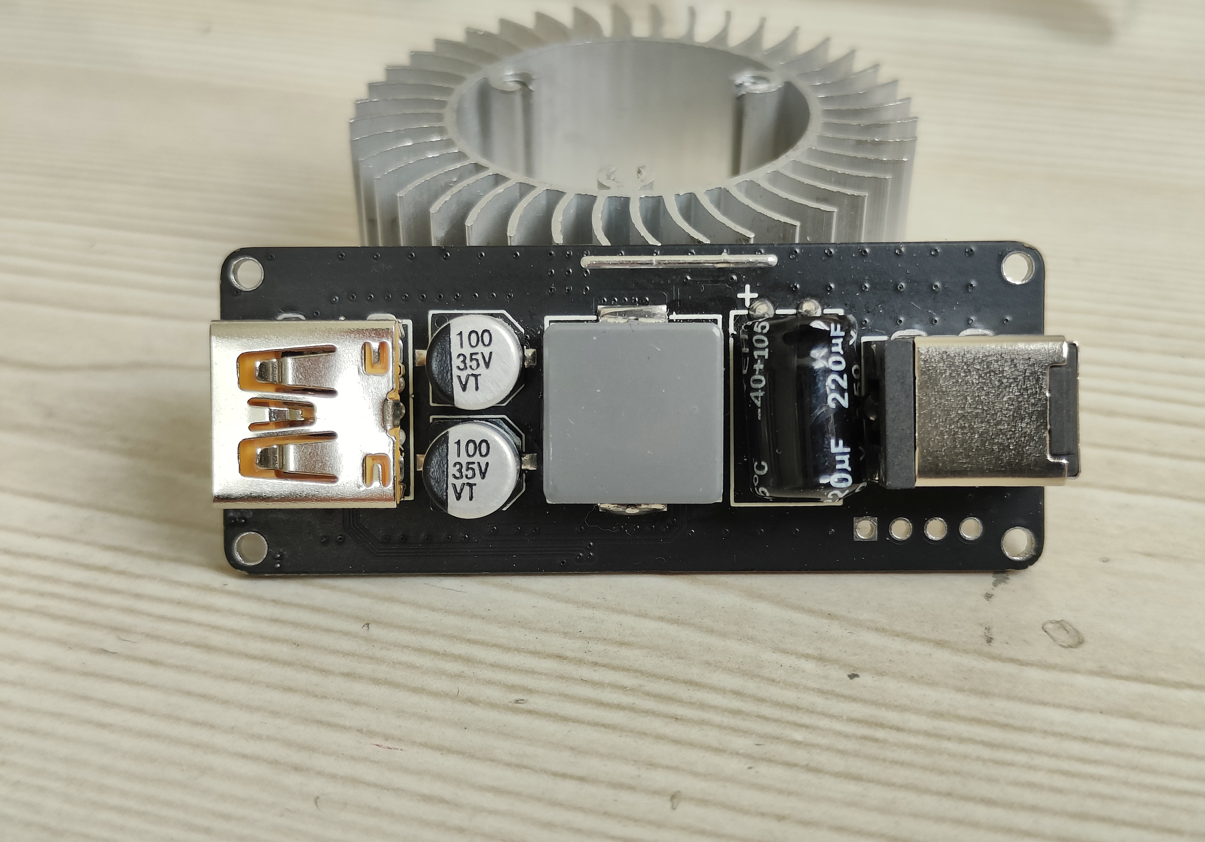
module uses the SW3538 chip and supports multiple charging protocols.
A maximum power of 65W is recommended; using 100W can cause the inductor temperature to exceed 100℃.
At 8W~100W power, using a purely resistive load, the measured ripple is approximately 230mV.

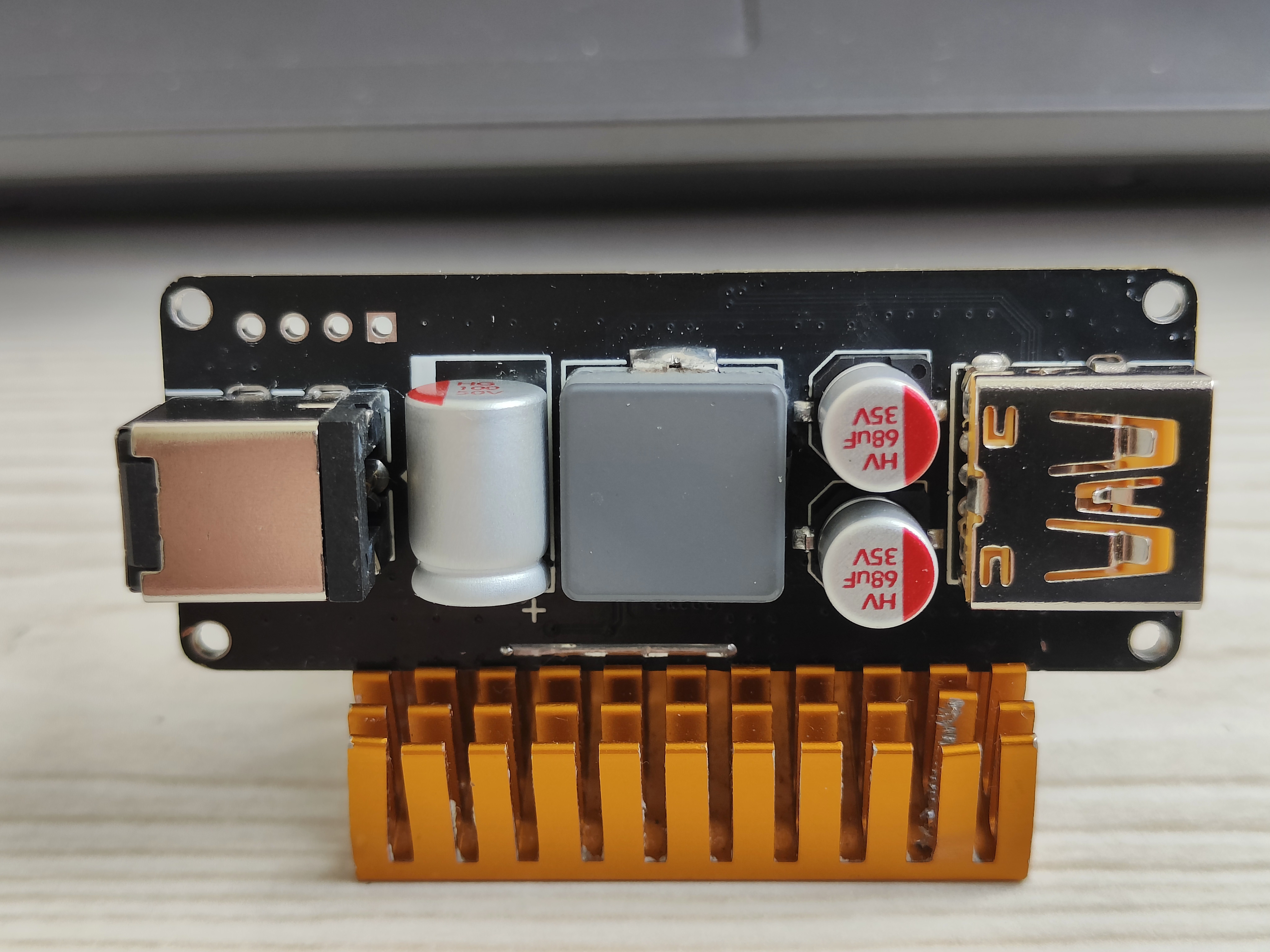
Ripple optimization explanation
: Optimization method: Replace all electrolytic capacitors with solid-state capacitors.
Test results: Using a purely resistive load, at 8W~100W power, the ripple is within 90mV.
Note: Between 8W~100W, the ripple remains almost unchanged.
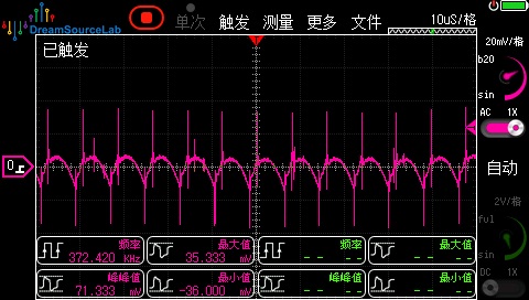
Ripple test screenshots:
Unloaded ripple,
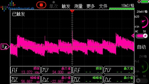
Loaded ripple,

Optimized appearance.
PDF_sw3538 charging module, maximum 140W output.zip
Altium_sw3538 charging module, maximum 140W output.zip
PADS_sw3538 charging module, maximum 140W output.zip
BOM_sw3538 charging module, maximum 140W output.xlsx
92186
IP5353 power bank
IP5353 compact power bank
On September 17th, some users reported encountering severe overheating issues; the cause is unknown. The issue will be re-uploaded after resolution.
The power bank uses the Ingenic IP5353 chip, and the USB-A port supports 18W fast charging.
This power bank PCB
has a ripple of less than 50mV at 5V 1.5A output
and less than 150mV at 9V 2A output.
For details, please refer to the attached video. Select the R5 resistor value to configure the battery voltage NC (not connected): 4.2V 68K, 4.3V 33K, 4.35V 10K, 4.4V.
[Link to video: https://www.bilibili.com/video/BV12D4YewE7M/?spm_id_from=333.999.0.0&vd_source=bcdc30aa0aef1fd155042819e71edf94 ]
Power Bank PCB Structure V2.dxf
September 9.mp4
PDF_ip5353 power bank.zip
Altium_ip5353 power bank.zip
PADS_ip5353 power bank.zip
BOM_ip5353 power bank.xlsx
92187
Old Wang's JDI Memory LCD baseboard
After a long time, I finally got it working!
References:
1. 0.96-inch JDI_LCD baseboard
2. Lao Wang's 0.96-inch MLCD adapter board
ESP32C3 Arduino driver example:
1. Wiring:
SCL-4
SDA-6
CS-1
DISP-0
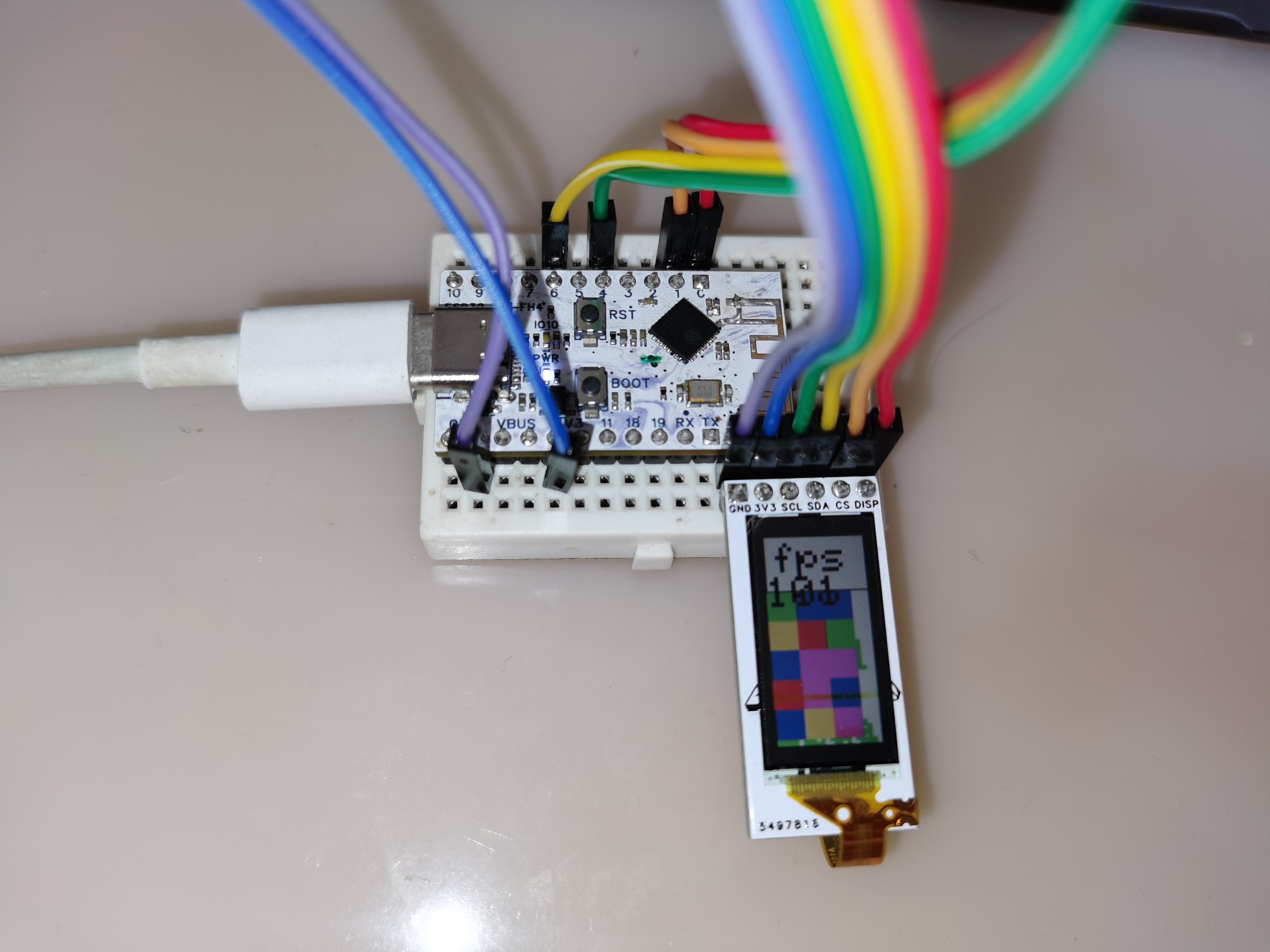
2. Download and install the required libraries. Thanks to Gan Cao for providing the link: https://github.com/Gbertaz/JDI_MIP_Display.

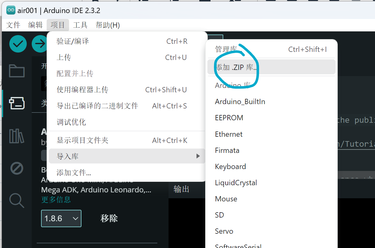
You can also install directly via Arduino, but it seems to cause errors.
3. Modify the configuration file.

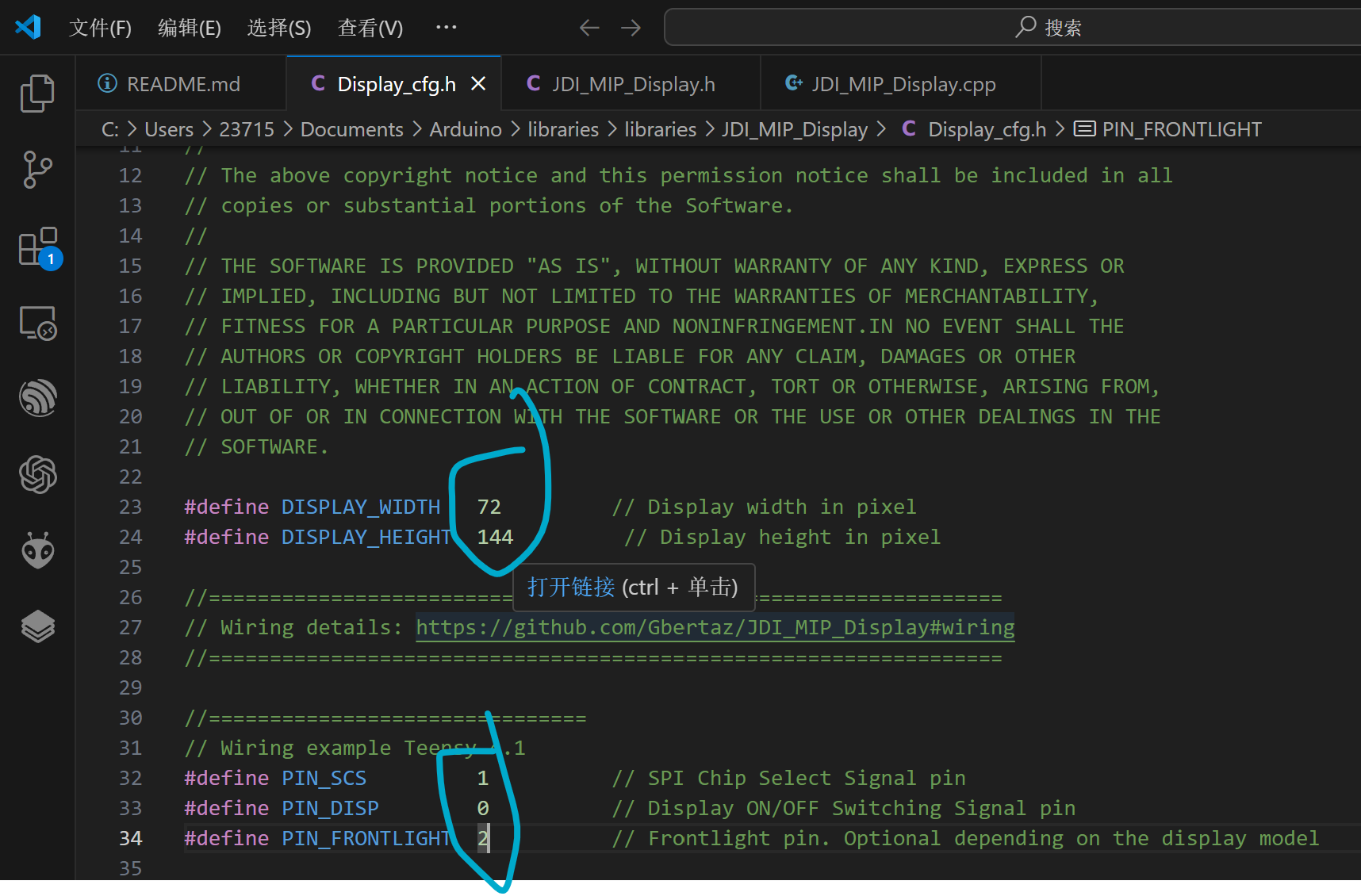
The SCL (SCLK) and SDA (MOSI) pins are automatically assigned based on the microcontroller model. On my ESP32C3FH4, they are 4 and 6.
4.
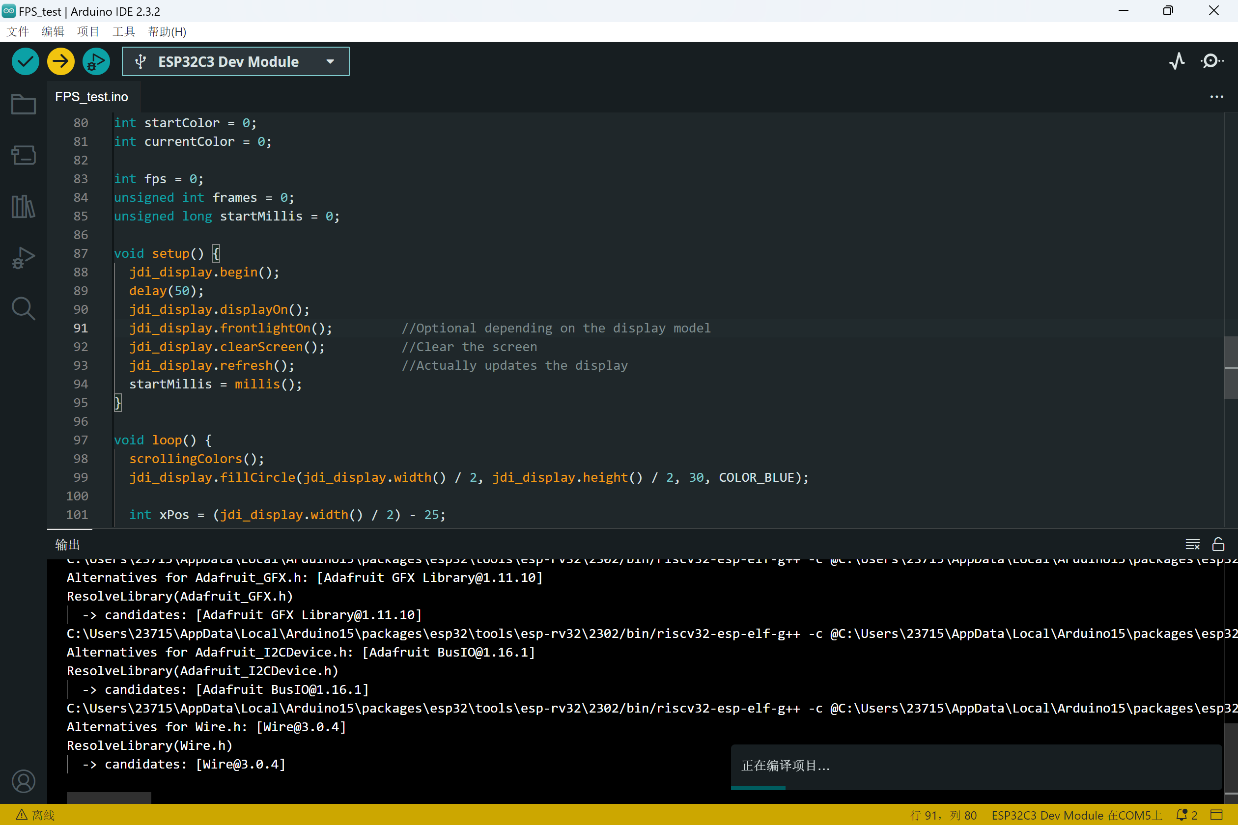
Notes on compilation and download:
1. This library seems to enable HSPI and DMA by default, therefore it has certain requirements for the microcontroller model
. 2. The example project and the modified library have been uploaded as attachments.
3. The power supply pins should be connected to 3V3.
FPS_test.rar
JDI_MIP_Display.rar
wx_camera_1726546570558.mp4
VID_20240917_153914.mp4
PDF_Old Wang JDI Memory LCD Baseboard.zip
Altium_Old Wang JDI Memory LCD Baseboard.zip
PADS_Old Wang JDI Memory LCD Baseboard.zip
BOM_Old Wang JDI Memory LCD Baseboard.xlsx
92188
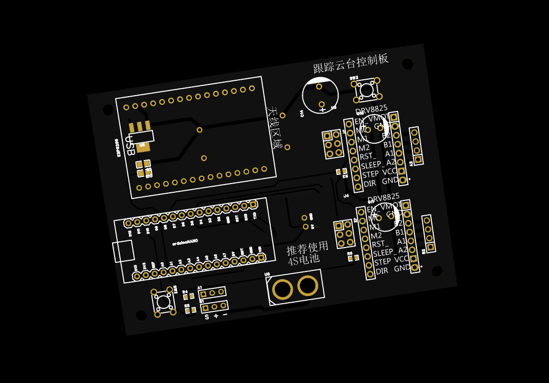
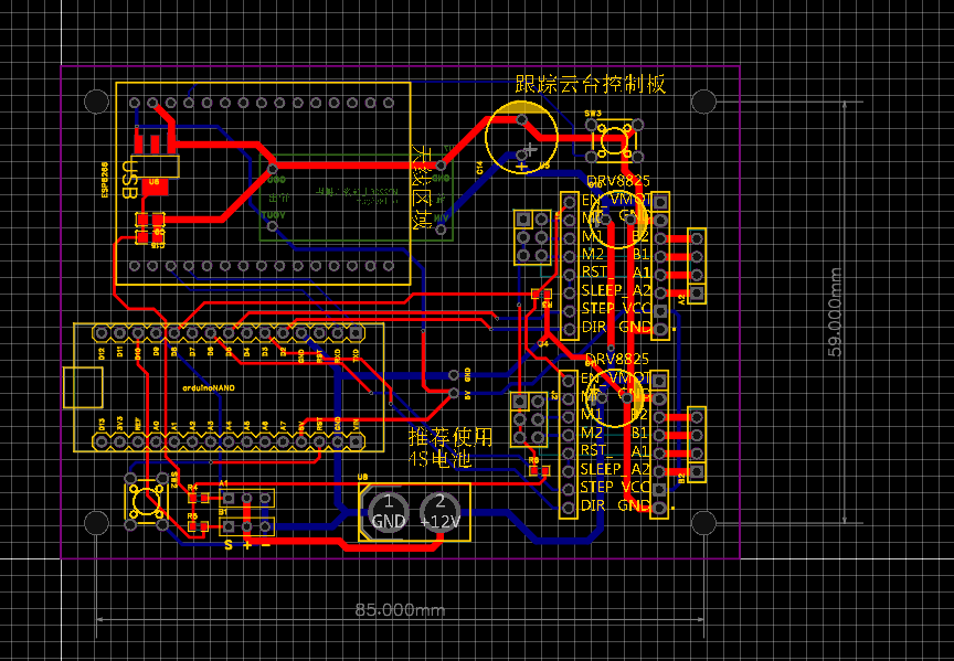
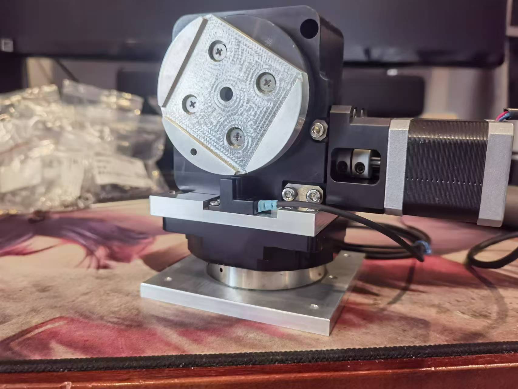
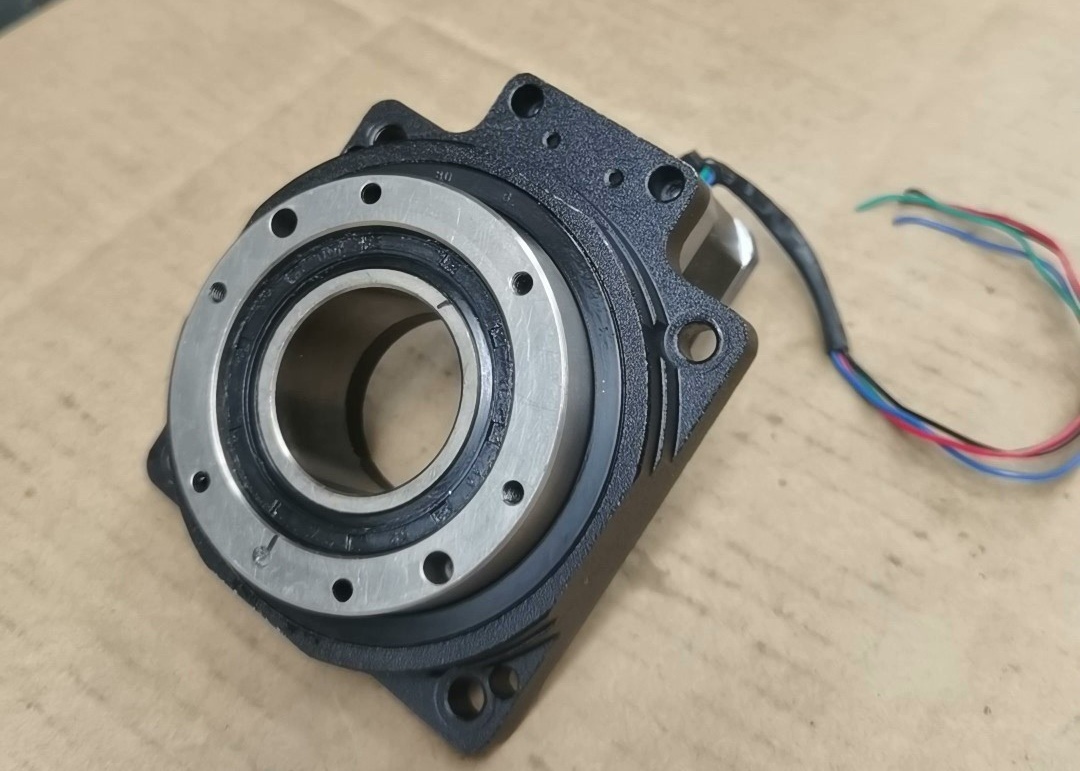
Look4Sat satellite tracking gimbal stepper motor speed reducer version
The satellite automatic tracking gimbal communicates with satellites. Holding the antenna while your hand gets tired, but this one keeps your hand from getting tired.
September 17, 2024 Update: V1.2
1. This update primarily redesigns the PCB, using a 5V power module to resolve the insufficient 5V power issue of the 1117 chip.
2. Updated printed parts, added CNC parts, and allows selection of one of two types of connectors.
MP2236 Power Module
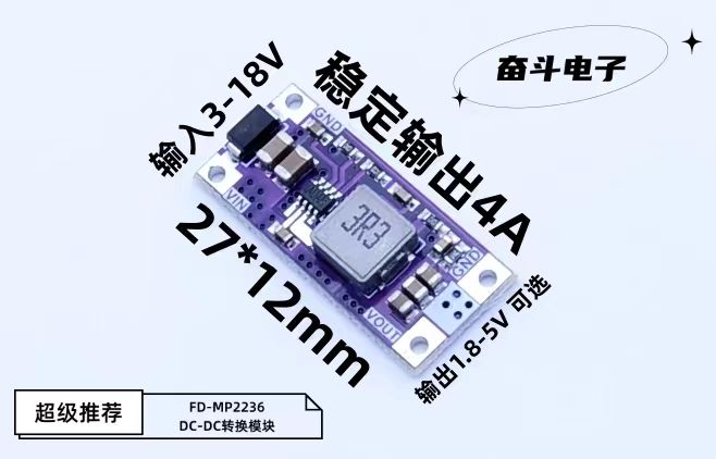
(July 18, 2024):
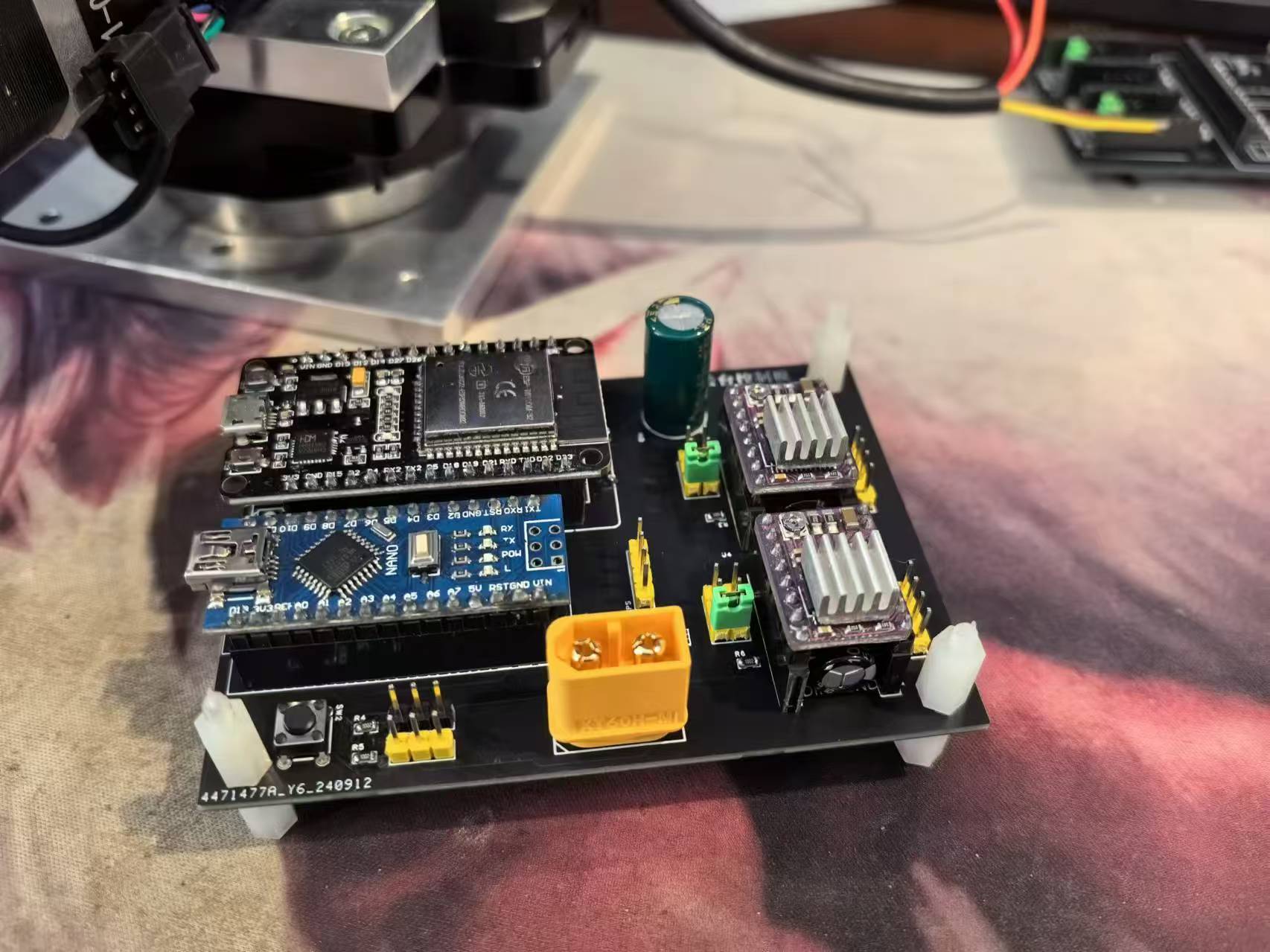
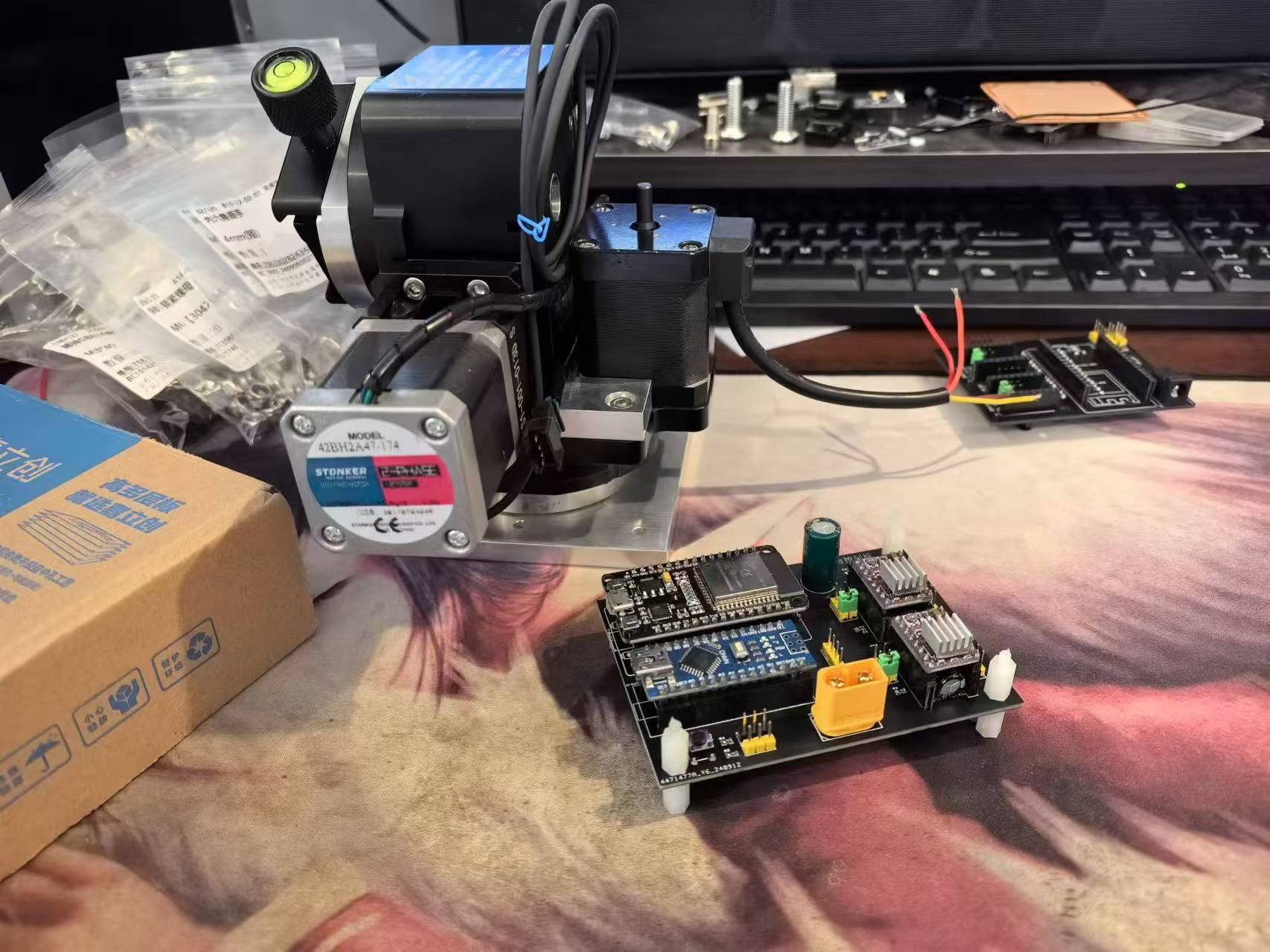
Look4Sat satellite tracking gimbal, using Arduino Nono and ESP8266, along with two photoelectric limit switches, controls two stepper motors or a rotating platform, allowing the antenna to track and point at the target satellite in real time.
Achieves high-precision pointing at a relatively low cost.
Main components
: Pitch uses a Cree 9060 worm gear turntable with a 1:60 reduction ratio
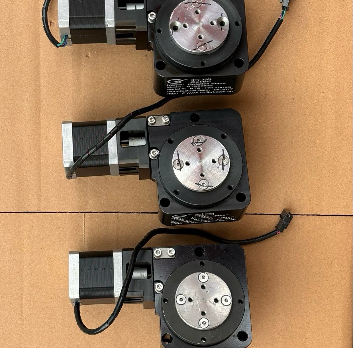
; Direction uses an unnamed MD85 turntable with a 1:18 reduction ratio
; Limit switches are photoelectric limit sensors. NPN type signals are required, with a 5-24V power supply.
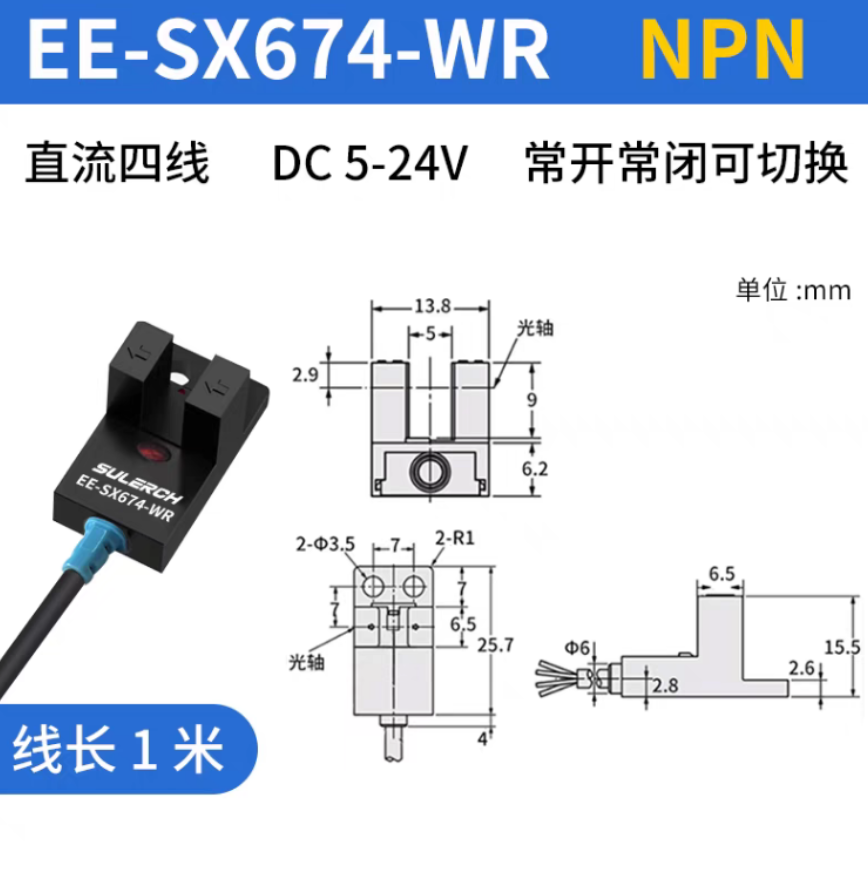
These are the components I used; they may not be the same as mine. For the mechanical parts, those with the capability can 3D print all mechanical and reduction parts; only 42 stepper motors need to be purchased.
The reduction ratio can be calculated and modified independently. The limit sensor doesn't necessarily have to be a photoelectric sensor; any NPN type with a 5-24V signal power supply will suffice. One M8*16 flathead screw, four M4*20 countersunk screws, and four M4 anti-slip nuts are needed for connecting the two turntables and the printed parts.
Six M4*12 flathead screws are used to connect the base. One 1/4 to 3/8 camera adapter screw is used to install the quick-release plate. Six M4*8 flathead screws are used to install the antenna mounting plate. Six M3*40 screws are used to install the antenna . Several M3*8 screws are used to install accessories. Other limit sensors are not required if automatic zeroing is not needed. The original design was for base station installation, requiring only one adjustment to true north. Note! A limit sensor must be installed for pitch. The program printouts are attached. If you have an optimized version, please leave a comment. Finally, the program can be directly copied to the Arduino IDE and the corresponding libraries installed for compilation. Compiling with Arduino NANO and ESP8266 is very simple.
Receive SO-50.mp4
Must Read!!! Instructions.txt
Pitch direction automatic calibration stable version.zip
Mechanical Selection Instructions.docx
CNC.zip
3D printing.zip
PDF_Look4Sat satellite tracking gimbal stepper motor reduction version.zip
Altium_Look4Sat satellite tracking gimbal stepper motor reducer version.zip
PADS_Look4Sat satellite tracking gimbal stepper motor reducer version.zip
BOM_Look4Sat satellite tracking gimbal stepper motor reduction version.xlsx
92190
Electronic circuit with three sets of running lights
Three sets of running lights in electronic circuit
The three sets of flowing light circuits
integrate XL-302SURD
MF1/4W-4.7KΩ±1% T
RI40-1/2W-470KΩ±2%
ERS1HM4R7D11OT
WJ500V-5.08-2P
9013
8a70115dab3e343d630127d409e3f918_raw.mp4
PDF_Electronic Circuit Three-Group Flowing Light Circuit.zip
Altium_Electronic Circuits Three-Group Flowing Light Circuit.zip
PADS_Electronic Circuits Three-Group Flowing Light Circuit.zip
BOM_Electronic Circuit Three-Group Flowing Light Circuit.xlsx
92193
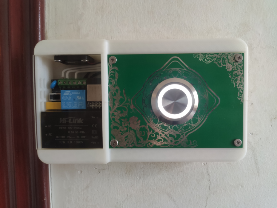
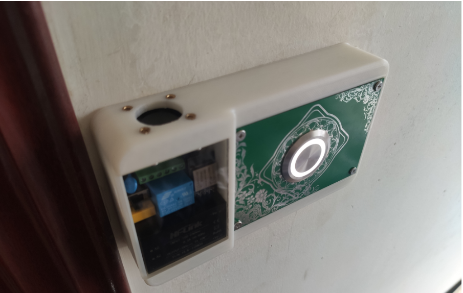
WiFi switch box
This document describes a method for controlling home lighting, and includes the source code for a microcontroller, an Android app, a PC app, 3D printing files, schematics, and PCB layout.
The screw hole spacing is suitable for common 86, 118, and 120 switch boxes, i.e., 60mm and 83-86mm. The switch box requires a neutral wire;
3D printing uses at least 15% filler. The off support
button uses a 30mm stainless steel button, similar to an elevator button. The button vibrates quite severely, so the debounce time is set to be relatively long. The button has an indicator light, which can be set to always on, always off, or in automatic mode (indicator off when relay is on, indicator on when relay is off).
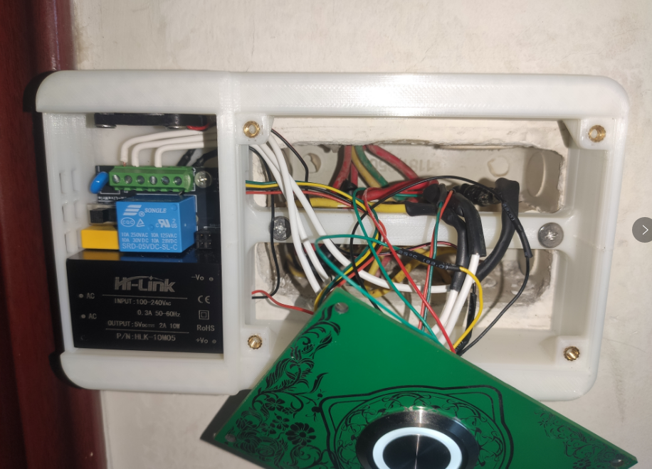
The controller uses AI-WB2-01S, which the seller claims has passed a 1000-hour test in an 85°C, 85% humidity environment, but the development environment is not very friendly.
There is a small cooling fan with a 40°C temperature switch connected in series. Normally, the fan is difficult to turn on, but it should be useful in hot weather. The 5V power supply is from the WIFI switch module.
The 4-pin connector of the WIFI switch module leads to two GPIOs, 3.3V, and GND for connecting to the button panel. One is for button interruption, and the other controls the indicator light on the button.
The Android APP uses Android... The software was developed using a software development platform (SDK), the PC app is written in Python, and the microcontroller uses the official SDK provided by Anxinke and the Eclipse IDE. It lacks automatic network configuration; you need to manually input your Wi-Fi name, password, IP address, and port number into the source code. Therefore, the

compressed file directory will not work directly.

202409161516.mp4
ce0dcb1c28c5c51dd227ca00124c9ff5.mp4
bacb13cb44ca46394a77730951b3c758.mp4
WiFi switch box.zip
a0de7dbdcde0c926755c8dde3e7ac8d2.mp4
PDF_wifi switch box.zip
Altium_wifi switch box.zip
PADS_wifi switch box.zip
BOM_wifi switch box.xlsx
92194
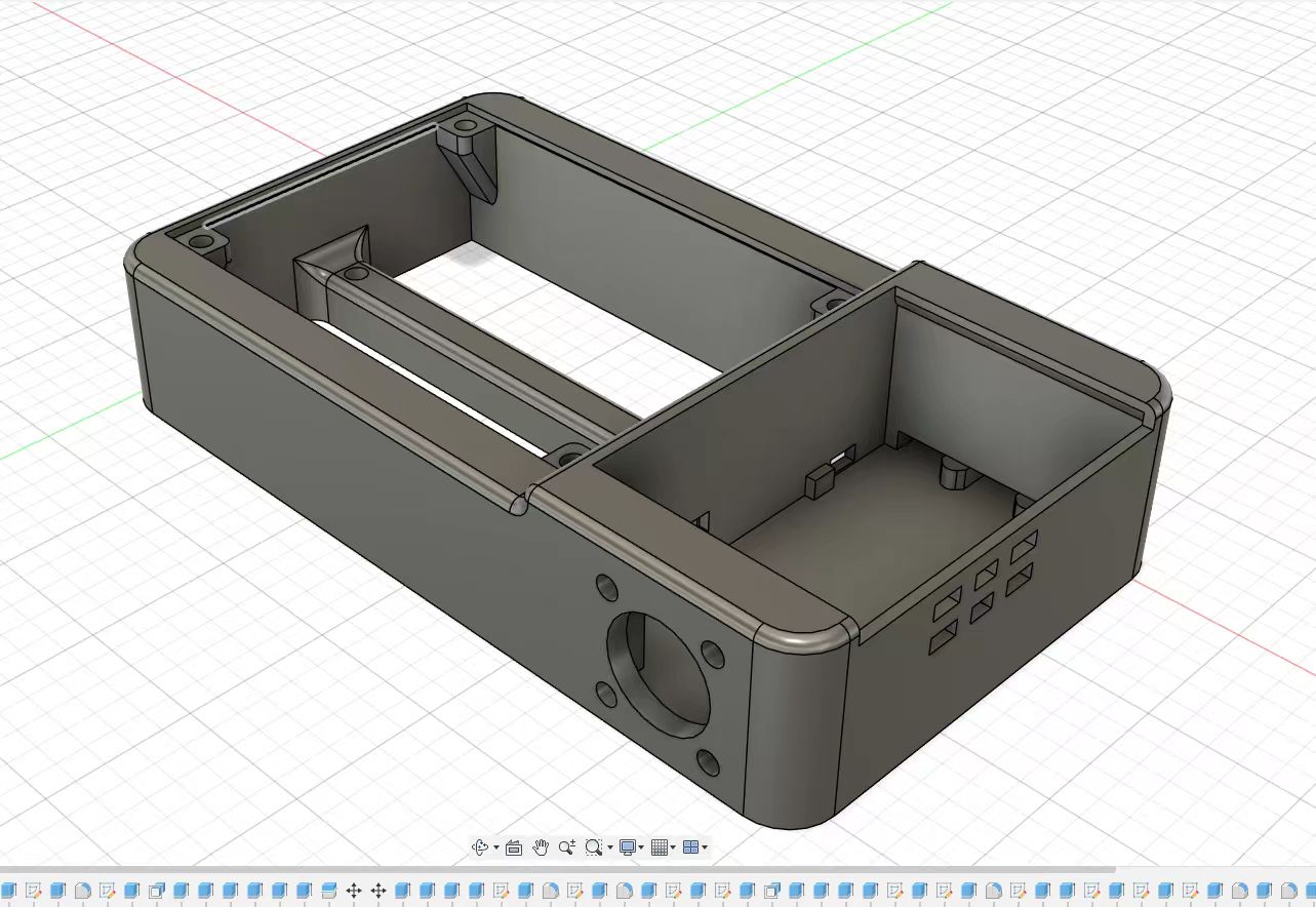
ChisFlash V1.0 Open Source GBA Flashcart
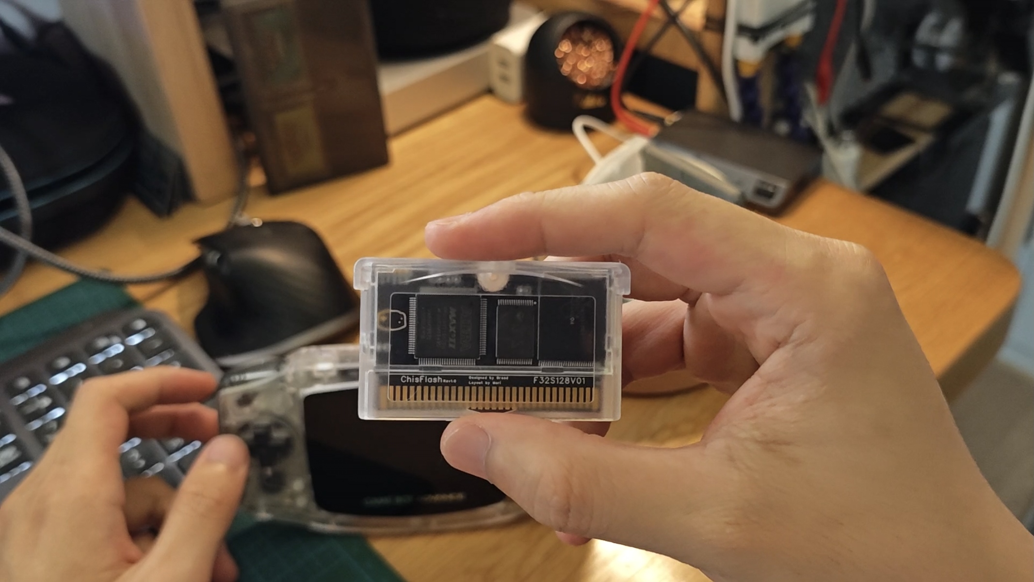
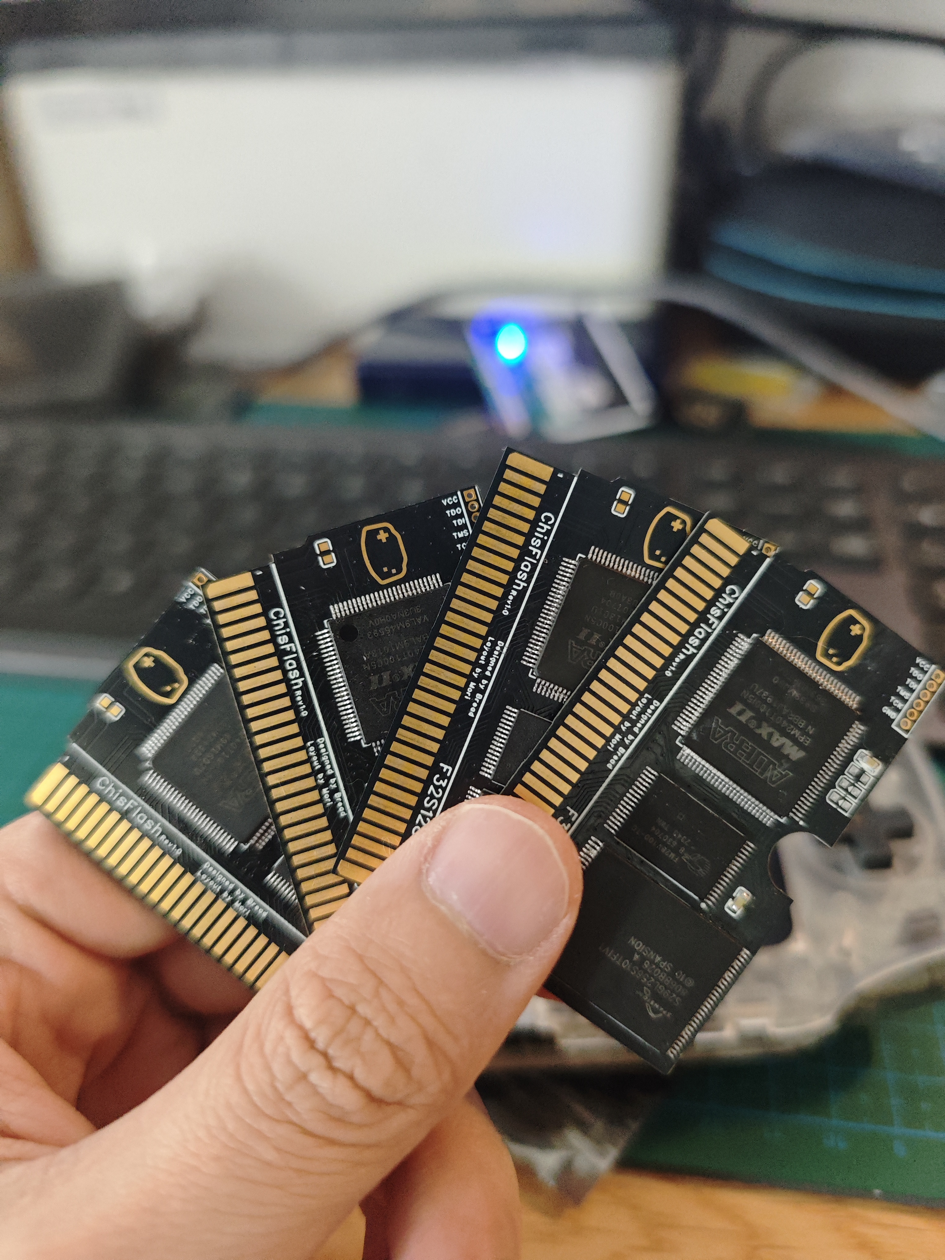
ChisFlash V1.0, codenamed Prometheus, was the first open-source GBA flashcart in the ChisFlash series and also the most versatile in terms of functionality.
Introduction:
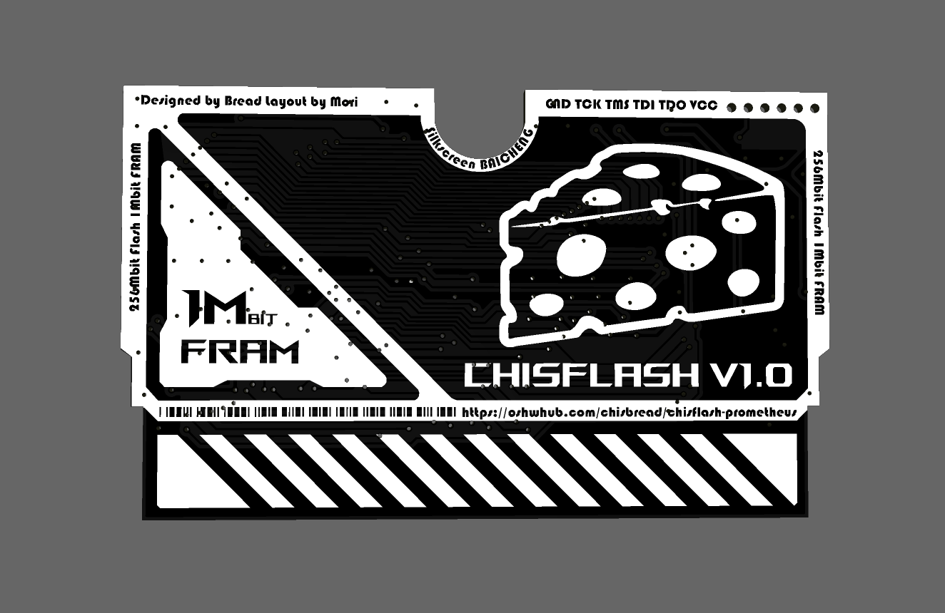
ChisFlash V1.0 (Prometheus) uses 256Mbit Flash and 1Mbit FRAM, compatible with 99% of GBA games, and supports NDS and GBcartRW burning.
Important Notes:
The PCB thickness should be 0.8mm.
Currently in beta testing, firmware can be obtained from the QQ group. After beta testing, the firmware code will be open-sourced on GitHub.
Learn more about
the GitHub project address, which will include firmware source code and GBA cartridge principle analysis (to be uploaded): https://github.com/ChisBread/ChisFlash. Join
the QQ group (771688226)
for project progress, tutorials, material pitfalls, black gold PCB material card group buying (voluntary group buying, non-profit), and finished product exchange and demonstration.
Finished Product Demonstration
Video
: [ChisFlash] Can you use 2u immersion gold PCBs within a budget of 30 yuan? The first wave of DIY all-in-one GBA flashcarts has already departed - Bilibili】 https://b23.tv/K90WHhc
Image
thanks to
@laqieer's opencartgba project https://github.com/laqieer/opencartgba
@mori for the excellent layout
@白橙's silkscreen design
and all the players who selflessly contributed to the GBA, let's preserve our childhood memories forever on the internet!
PDF_ChisFlash V1.0 Open Source GBA Flash Cart.zip
Altium_ChisFlash V1.0 Open Source GBA Flashcart.zip
PADS_ChisFlash V1.0 Open Source GBA Flashcart.zip
BOM_ChisFlash V1.0 Open Source GBA Flash Cart.xlsx
92195
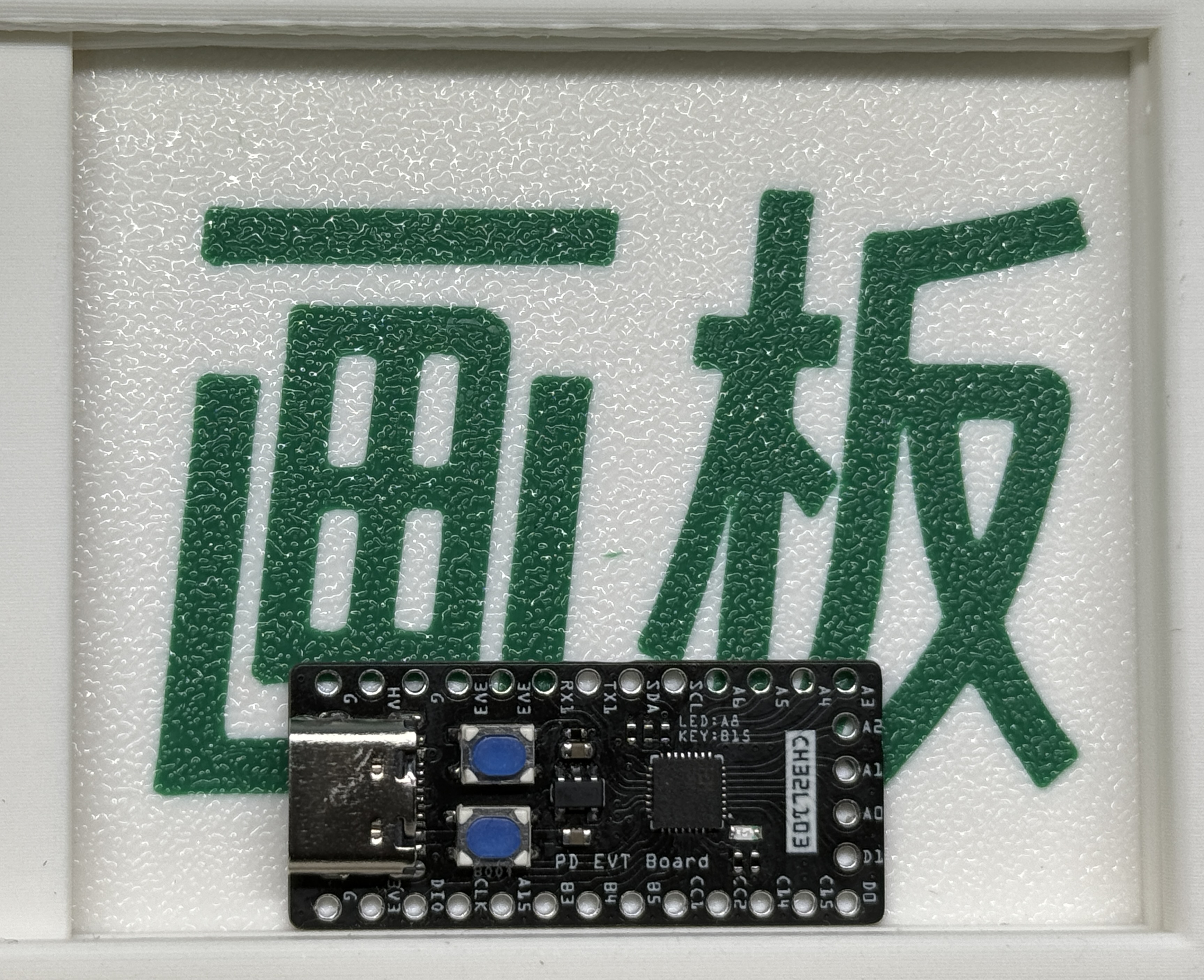
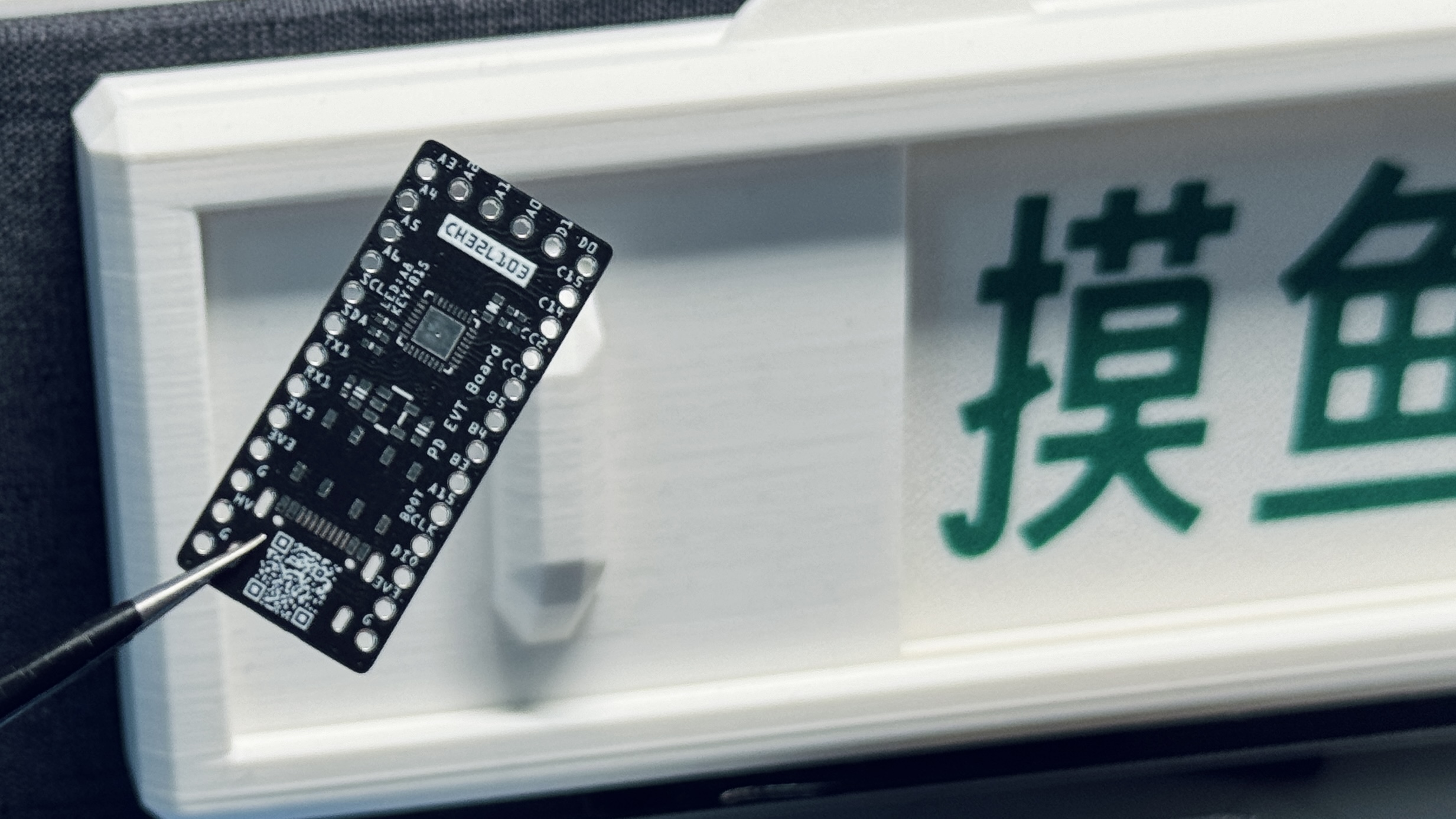
CH32L103 PD Development Board
Based on CH32L103, PD development board.
Based on CH32L103, PD development board.
[Commercial use prohibited]
1. The Type-C
project itself uses the CH32L103 development board, which includes a key and LED for operation.
The step-down uses an LDO, outputting 100mA
compatible with WCH's CH32L103 protocol (IO needs modification). Later, it may be modified based on the PD protocol provided by WCH to induce 5V, 9V, 12V, 15V, and 20V respectively when a button is pressed.
2. Project progress
[2024.09.17]
[V1 version] Added software example, inducing 5V, 9V, 12V, 15V, and 20V respectively when a button is pressed sequentially. Simultaneously, the LED serves as an indicator for the correct orientation of CC1 and CC2; the LED lights up when CC2 is pressed.
Modified based on the WCH official website example program
[2024.08.20]
[V1 version], release version
3. Image gallery.

Light up.mp4
5-20V.mp4
CH32L103_KEY_PD5_20V.hex
PDF_CH32L103 PD Development Board.zip
Altium_CH32L103 PD Development Board.zip
PADS_CH32L103 PD Development Board.zip
BOM_CH32L103 PD Development Board.xlsx
92196
electronic


 京公网安备 11010802033920号

 1017490000


