Disclaimer:
This design is for tinkering and technical learning purposes only, and is not recommended for use in a production environment.
The author will not be responsible for any losses incurred as a result.
It is not recommended to build this without any VNA.
Using a JLC-based two-layer board offers no impedance guarantee, so your measured results may deviate from the expected performance; this is normal.
Due to the poor high-frequency loss of the free board, I still recommend purchasing a reputable brand-name antenna with proven performance. (Advertisement space for rent (x
antenna belongs to the religious field. I respect and tolerate your beliefs, and I also hope you can tolerate others who are different from you. Thank you.
Open source license: CC BY-NC-SA 4.0.
What is this?

This kind of antenna is very cheap on Taobao, buy one get five free, and the effect is quite good at certain frequencies (actually tested at frequencies with VSWR<1.3 in the 5.2/5.8 band).
Although the PCB it uses is also FR4 or similar, the thickness is only 0.4/0.6mm, which is better than the 0.8mm available from LCSC.
Although it is feasible to design and simulate the antenna myself using HFSS, the high-frequency performance of the board material is very expensive to prototype, so I want to use this commercially available finished antenna to make the smallest unit array.)
...Just messing around, the cost is only a few dollars anyway. If it works well, we make a profit; if not? You can't criticize me for something this unreliable...
Open-source digital image transmission antenna kit for beginners: Buy 1, then you'll receive 6. 1 for transmitting with an 8731 + homemade PA, 1 for omnidirectional reception, and 4 arrays for directional reception—it's such a perfect
design
... There's not much to design; everyone draws finished antennas the same way.
Each antenna contains two dipole elements. Considering that a narrow beam isn't practical, four are arranged horizontally, equivalent to a 2x4 array.
The horizontal spacing is best at about 1/2 wavelength, but even a 10% difference won't suddenly make it unusable; I just drew it randomly based on intuition.
So you only need to make a 1-to-4 splitter on the board using microstrip lines. A T-junction power divider is actually used, with all ports at 50 ohms and a 70.7 ohm 1/4 wavelength impedance transformation in the middle. If you're curious, there's an ADS in the schematic. Screenshot of the schematic diagram.
The reflector works by mirroring and coherently superimposing elements. The ideal spacing is 1/4 wavelength (reflection is equivalent to shifting 180°, so the total path is 360°). In reality, due to the presence of the medium, it needs to be slightly less than 1/4 wavelength. The design here starts at 12mm, which you may need to fine-tune; however, without an anechoic chamber, adjustments are just rough and will be usable.
BOM
PCB: Two layers, 0.8mm total thickness .
Excluding the PCB and all components on it (…only one SMA and four IPEX), you will also need:
a buy-one-get-five-free antenna, with a wire length >= 30mm. However, this wire length will cause losses.
200mm x 200mm x 1mm aluminum plate, used as the reflector; I bought two M3x3 screws (free shipping)
and 10
M3x12 (length may need fine-tuning) copper pillars, 5
M1.0x3 screws, and 8
M1.0 nuts on Taobao for 3.x yuan.
If you make 5 at a time… A complete set, including common tools, and a PCB (borrowed), can be made to cost 5 yuan or less per set.
M3 is used to fix the PCB to the reflector, while M1.0 is used to screw the antenna
onto . The M1.0 holes on the antenna need to be drilled yourself; however, if you're too lazy to drill, you can use a piece of foam cut to about 10mm thick and placed between the reflector and the antenna
. Besides common electronic building tools, you'll also need the following:
an electric drill/hand drill
(1.0mm/3.0mm drill bits for aluminum plates) ,
sandpaper, or similar materials.
Testing
VSWR/antenna efficiency/maximum gain are three different things; please don't confuse them.
Based on my potentially incorrect (who has an anechoic chamber at home?) test results, compared to a single antenna of the same model, the array can achieve an approximately 5dB improvement in the maximum gain direction.
In short, it's better than a single antenna—a real bargain! Buy one, get five free! (
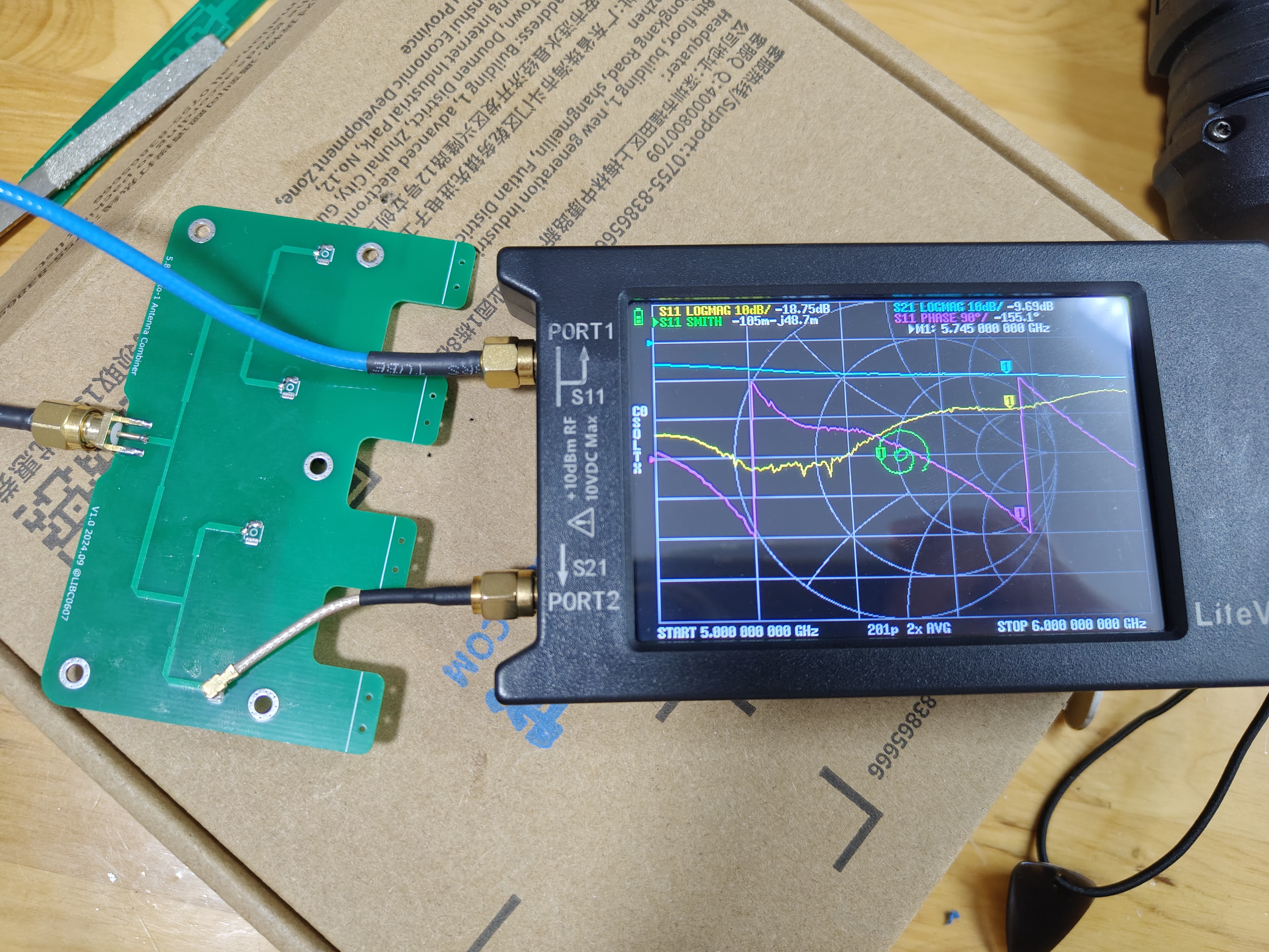
The images below are all under VNA conditions.) Port calibration (because I was too lazy to recalibrate), using the cable shown in the diagram, allows for a rough estimate of
the synthesized port's S11/VSWR:

Ports 3, 4, and 5 are shorted with 49.9 ohms. At this point, S11 & S21 (actually, 2, 3, 4, and 5 are roughly the same) .
Ideally, S21 should be -6dB, but the simulation will likely
show a slight increase of a few tenths of a dB. It's clear that even this small amount of wiring introduces significant actual losses. However, this 3dB loss is compensated for by the array gain.
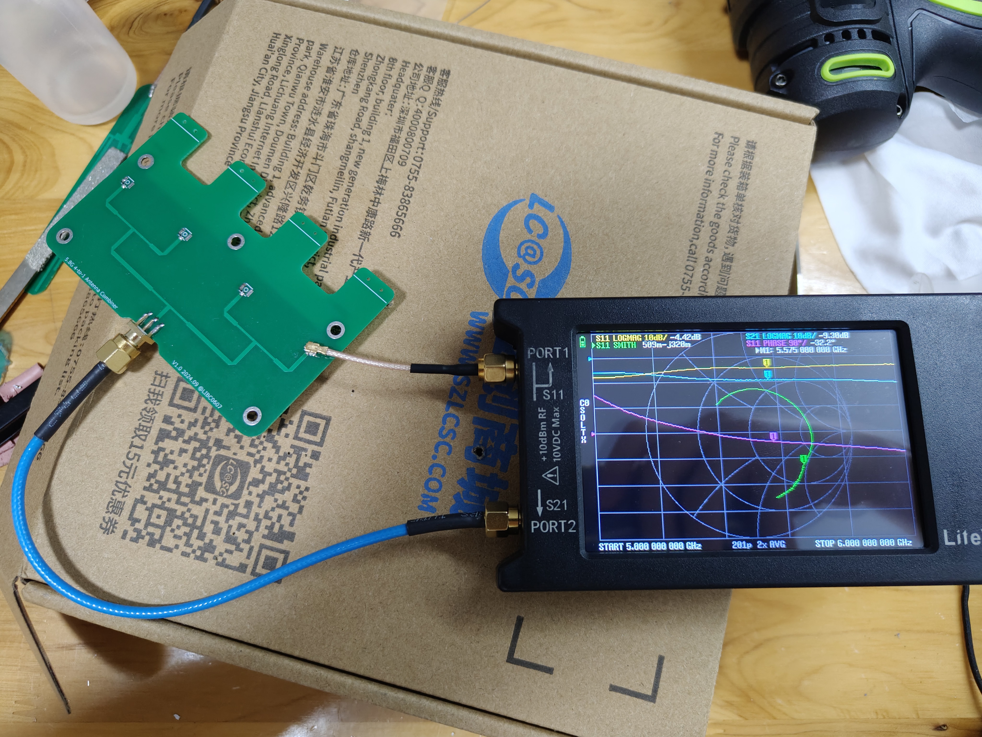
Referring back to the diagram, ports 3, 4, and 5 are shorted with 49.9 ohms. Swapping ports 1 and 2
doesn't work well; I tried my best.
I didn't measure the isolation between the antenna ports, but theoretically, this structure doesn't offer much isolation anyway.


 京公网安备 11010802033920号

 1N4937GPE/51


