The pulse width is adjustable, and the frequency is configured by replacing the resistor. It is suitable for driving brushless DC motors, such as fan motors. It includes a MOSFET switch for power off and an indicator light. See the PCB file for details, which includes calculation methods and usage instructions.
This design is based on an expansion board developed using the HC32F4A0PITB-Youth Edition. Its functions include reading satellite time and location information via a GPS module and reading temperature and humidity via an AHT20 sensor, displayed on an OLED screen. Future updates will include displaying current speed based on satellite positioning. It can be placed at home to monitor indoor temperature and humidity as well as a clock, or in a car to display vehicle speed and interior temperature and humidity.
A single-port USB flash drive board based on JMS583, with a PCB size of only 2.4cm*1.6cm.
First of all, thank you to @UUYK, @模成Electron, @an_ye, and @超人强 for their support of this project. This branch of the project participated in the 2024 Challenge Cup - Unveiling the Challenge Project; please do not use it for electronic design competitions or commercial applications.
The controller is the most commonly used JMS583, a USB 3.2 Gen2 10Gbps to PCIe 3.0 x2 converter. Its sequential performance is on par with the SM2321, and its random performance is superior to many high-end SSDs such as the SM2320.
Currently, it has been tested with Toshiba (Kioxia) BG3, Micron 2100, and Hynix BC711.
Previously, we struggled to find a crystal oscillator location for Samsung, only designing power supply compatibility. Fortunately, the project by the WESD team provided the location, making the project a success.
This project features an extremely complex six-channel external power supply: one 5V-3.3V LDO and one 5V-1.05V DC-DC power supply for the controller; three DC-DC power supplies for the three-phase universal power points of the BGA291; and the remaining channel for additional DRAM power for Hynix and Samsung SSDs that may require it. Therefore, this project theoretically supports almost all BGA291 SSDs on the market.
However, a word of caution: BG3 and BG4 SSDs based on BiCS3 and BiCS4 processes are very prone to firmware loss after heating, and this loss is often irreversible. Therefore, if you want to DIY, never buy BG3 or BG4 SSDs with adhesive backing. Most importantly, you need good craftsmanship and a short heating time. Excessive heating of some Samsung and Hynix SSDs with DRAM can easily cause bulging and short circuits. DIY is risky; proceed with caution.
The MP2122 in the BOM can be replaced with the SY8892. Use whichever LDO you prefer; USB connectors are much cheaper on Taobao. I admit that this project uses 0201 too much, which is very unfriendly to manual placement. I suggest opening the stencil, applying solder paste, and then using a small placement machine (unless you have a lot of patience).

PDF_BGA291 Single-C Ultra-Small Solid State USB Flash Drive Board.zip
Altium_BGA291 Single-C Ultra-Small Solid State USB Flash Drive Board.zip
PADS_BGA291 Single-C Ultra-Small Solid State USB Flash Drive Board.zip
BOM_BGA291 Single-C Ultra-Small Solid State USB Flash Drive Board.xlsx
92265
STC89C52 core board
STC89C52RC core board
The STC89C52RC core board features a Type-C power supply, a 12MHz crystal oscillator, two buttons, and an LED. It is not currently programmed.
Bilibili video: BV1qM4y1q7st.
Source: https://oshwhub.com/course-examples/51-dan-pian-ji-zui-xiao-xi-tong
abf83c421532f50c5c7ba2c4d07ddae.jpg
PDF_STC89C52 core board.zip
Altium_STC89C52 core board.zip
PADS_STC89C52 core board.zip
BOM_STC89C52 Core Board.xlsx
92266
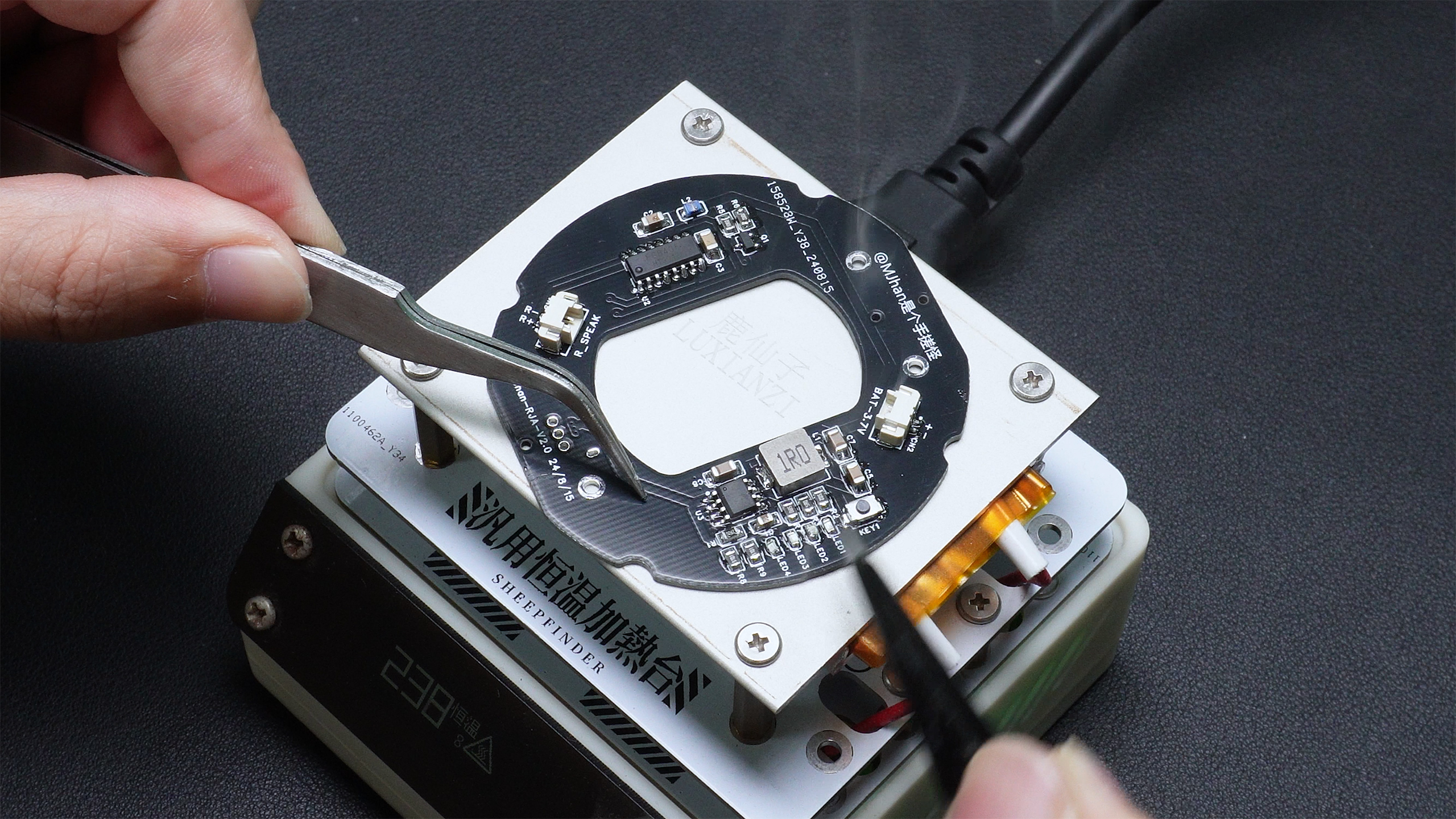
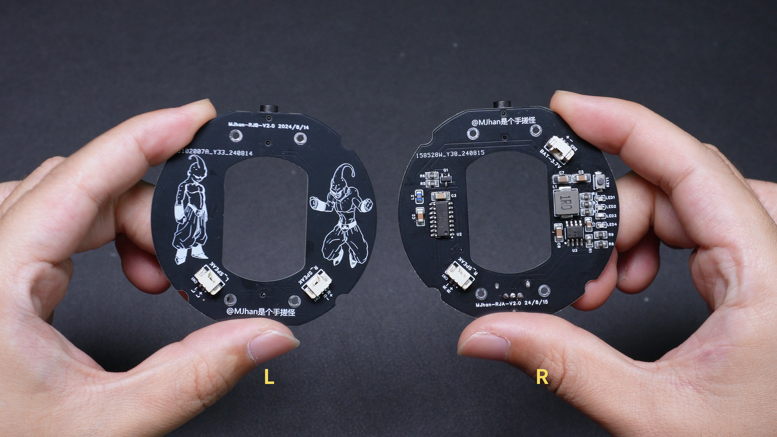
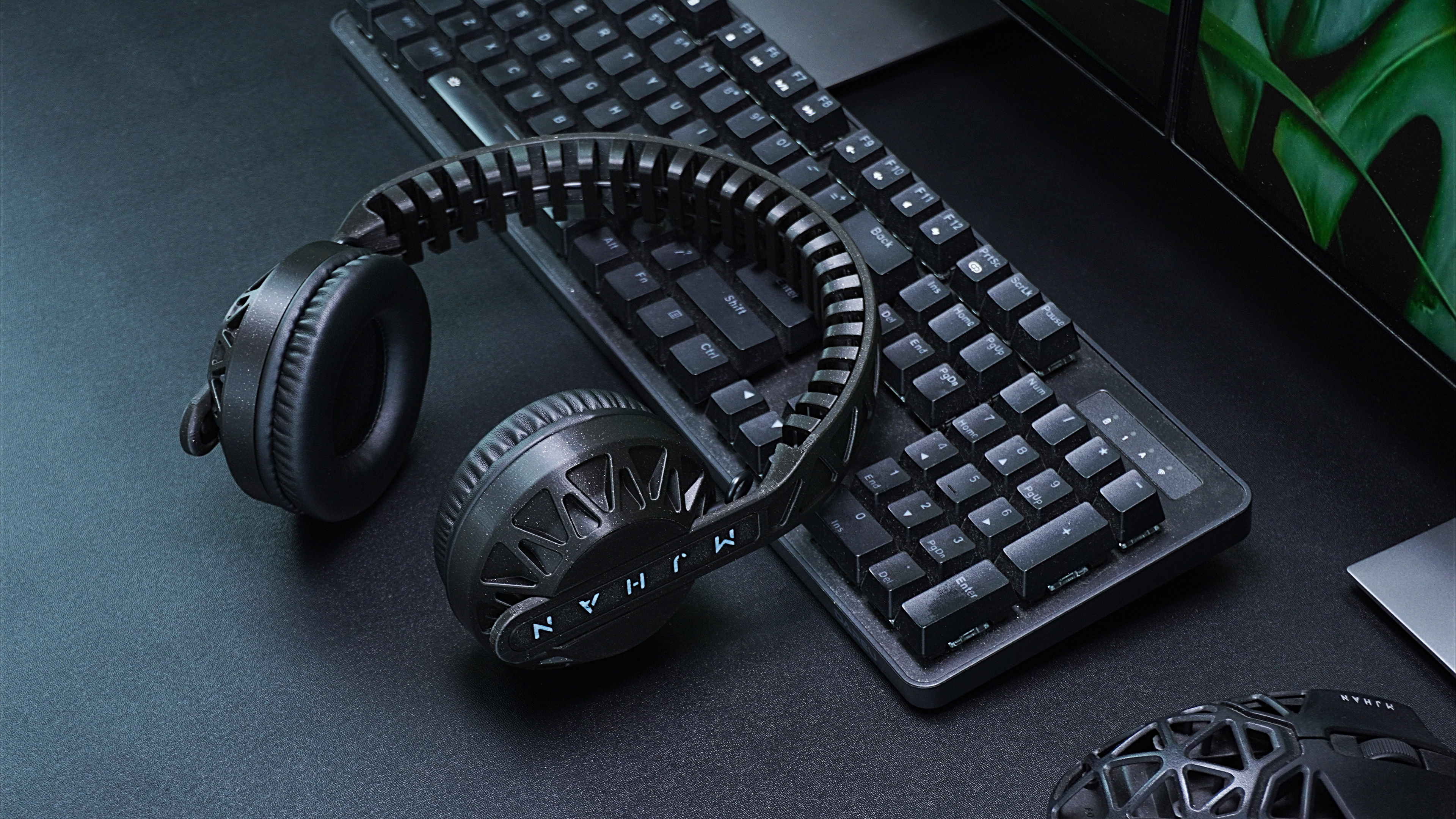
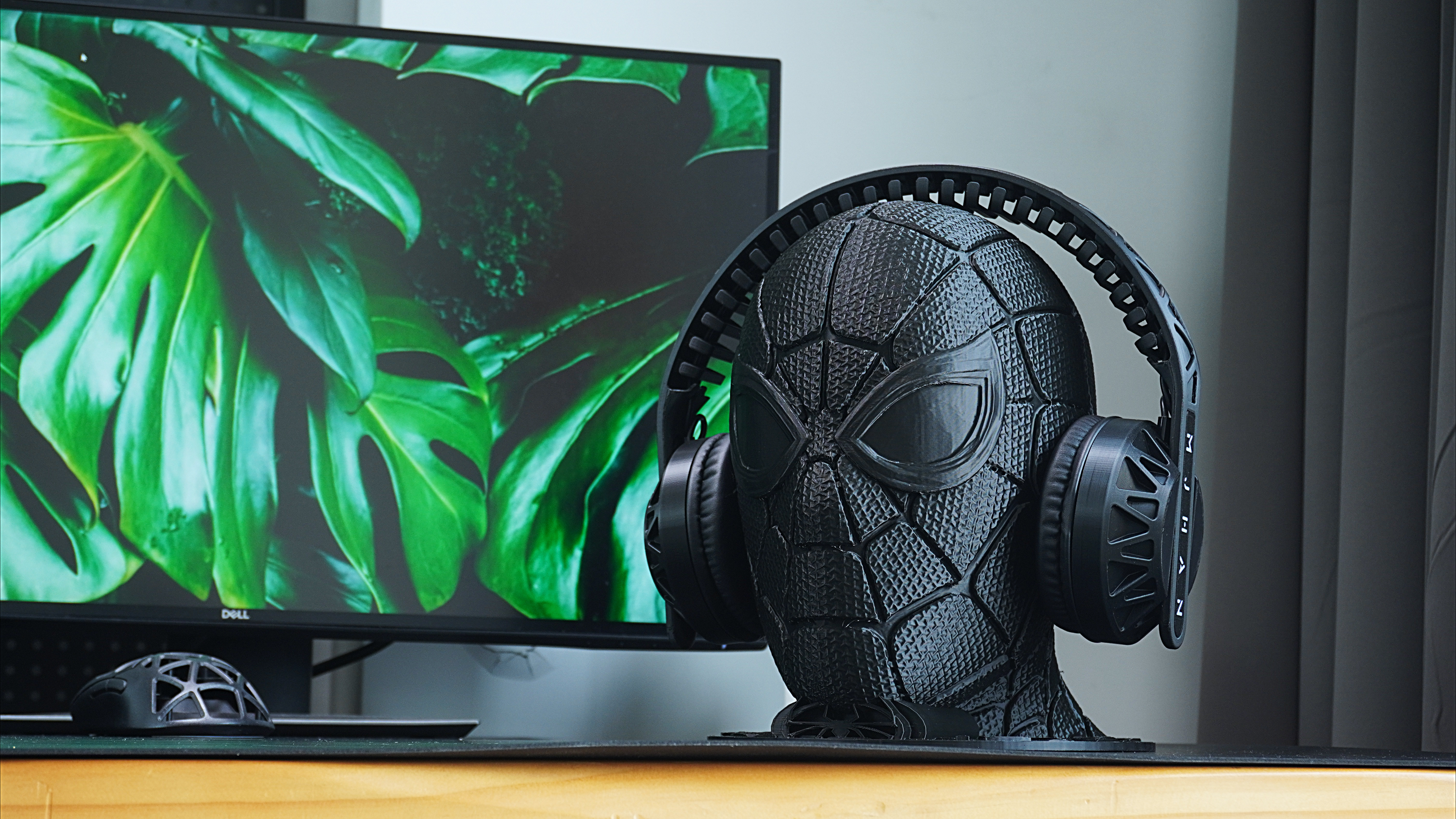
Over-ear Bluetooth Headphone Mainboard - M18 Bluetooth Module
This is a Bluetooth motherboard solution used in over-ear Bluetooth headphones, which has been verified and manufactured into a finished product!
This motherboard solution uses the M18 Bluetooth module, EG8405 power amplifier module, and IP5407 charging/discharging module,
combining these three modules to form a Bluetooth headset or Bluetooth speaker motherboard! It has been verified to be functional!
The circuit is simple, inexpensive, easy to debug and solder, making it ideal for DIY projects or beginners.
This Bluetooth headset project was designed and open-sourced by Bilibili UP master "MJhan是个手搓怪"!
The headset shell is 3D printed (FDM). See the Bilibili video for details on the open-source shell model.
The complete headset manufacturing process can be found on Bilibili (Video ID: BV1Y34negEvj,
to be added...).
PDF_Over-ear Bluetooth Headphone Mainboard - M18 Bluetooth Module.zip
Altium_Over-ear Bluetooth Headphone Mainboard - M18 Bluetooth Module.zip
PADS_Over-ear Bluetooth Headphone Mainboard - M18 Bluetooth Module.zip
BOM_Over-ear Bluetooth Headset Motherboard - M18 Bluetooth Module.xlsx
92267
CH32V203Test
CH32V203 Development Board
The CH32V203 development board features all I/O pins exposed, with reserved Type-C and download interfaces. It can accommodate an SPI-driven OLED screen and can also support an ESP8266 WiFi module.
PDF_CH32V203Test.zip
Altium_CH32V203Test.zip
PADS_CH32V203Test.zip
BOM_CH32V203Test.xlsx
92268
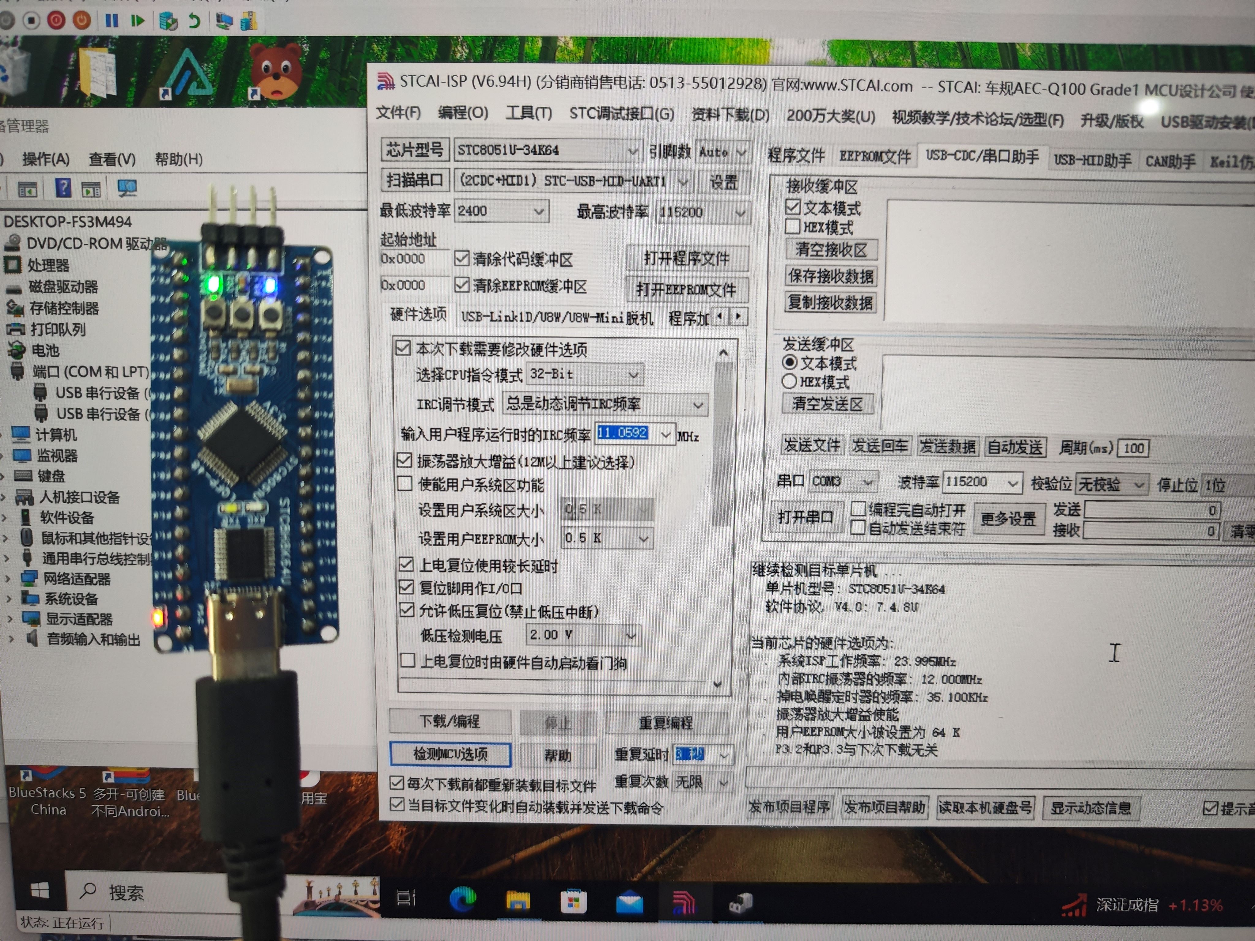
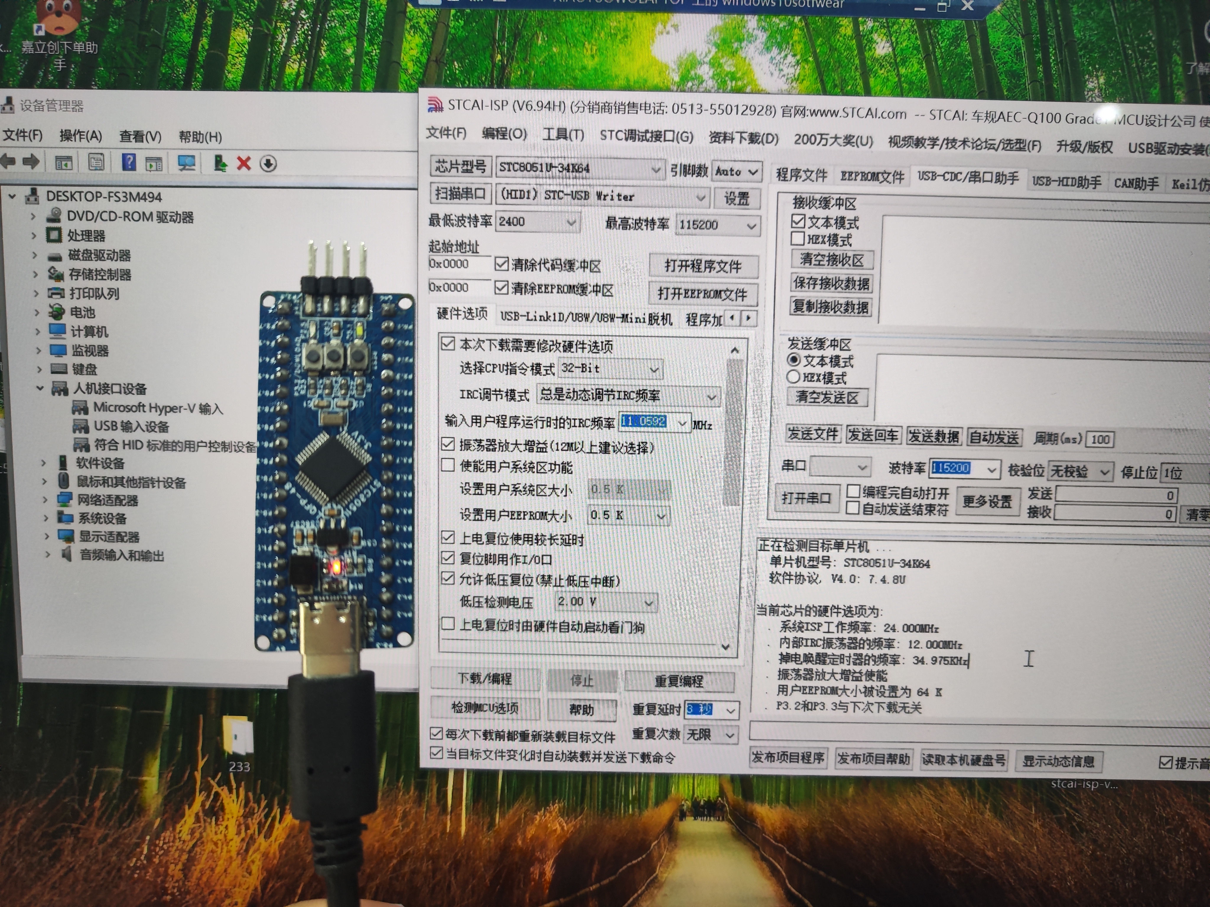
8051u Minimum System Board (Two Versions!)
I participated in the JLC and STC development board activities and made two versions. Because I was too lazy to work on them QAQ, I forgot about the open-sourcing part and ended up open-sourcing
the STC8051U microcontroller after the review deadline. Anyone interested can recreate it wwwww
Similarities: 1. Both boards have all GPIO pins brought out except for P5.6 and P5.7. 2. The pinout order is the same (meaning if you design an extended version, the two versions are compatible). 3. Both boards bring out P3.1, P3.0 5V, and Gnd, allowing for quick programming via an XH2.56 to DuPont converter (although they are all on the board). 4. Both boards have reserved pads for AT24CXX (you can solder them on if you like). 5. Power LED indicator and GPIO-controlled LED. 6. Uses an LQFP-48 packaged 8051U. 7. Also includes a reverse breakdown diode for voltage regulation (probably overvoltage protection). 8. Also includes a 0805 self-resetting fuse. 9. Both MCUs operate at 3.3V. Differences: 1. You can clearly see that... One board uses the STC8H8K64U for downloading (yes, I cut a portion of the schematic for a two-in-one solution, and both serial ports are brought out, one just doesn't have an LED...). (Supports automatic power-off downloading!). The other uses USB-HID for downloading (I made it length-equalized). (This definitely doesn't support power-off downloading). This one uses fewer components than the previous schematic and board, but of course, it also has some inconveniences! 2. The board with the STC8H8K64U supports switching between 3.3V and 5V download levels!!!! Use a 0-ohm resistor, but you can only solder one at a time! One at a time! (You wouldn't want to burn out a new board because you soldered it wrong...) 3. Regarding the button differences, refer to the schematic (I don't want to type anymore QAQ). (Simply put, to allow the STC8H8K64U to update the USB to 2-TTL program, two buttons are used, so the one for the user is gone...) (You have three, right? One is for the RST...) 4. Boards with STC8H8K64U can only install one SD card and one AT24Cxx (you can't insert two even if you want...) 5. Boards with STC8H8K64U have two more Txd and Rxd communication indicator lights. Regarding the download method: omitted for those with TTL... Regarding USB download, based on the documentation, after all soldering is done, press and hold the Download button before plugging in.
(Image)
VID_20240726_131632.mp4
PDF_8051u Minimum System Board (Two Versions!).zip
Altium_8051u Minimal System Board (Two Versions!).zip
PADS_8051u Minimum System Board (Two Versions!).zip
BOM_8051u Minimum System Board (Two Versions!).xlsx
92269
[Replica] Renesas-based desktop digital clock
[Replica] Renesas Desktop Digital Clock
1. Project Function Introduction:
This project replicates
the functions of LCSC's Summer Training Camp, including:
clock display,
alarm clock
, temperature and humidity display,
and date display.

PDF_【Replica】Renesas-based Desktop Digital Clock.zip
Altium_【Replica】Renesas-based Desktop Digital Clock.zip
PADS_【Replica】Renesas-based Desktop Digital Clock.zip
92270
Hezhou CC watch backplate
Hezhou CC Table Simple Extension Base Plate
Hezhou CC Meter Simple Expansion Baseboard
Update:
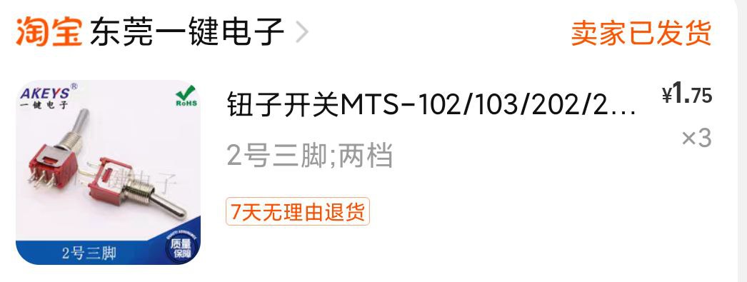
June 16, 2024: V3 Update. 1. Added CH22K PD decoy circuit; DIP switch configurable input voltage. 2. Replaced push-button switch with toggle switch; fixed poor switch contact; increased current carrying capacity (V2 casing compatible with V3).
December 12, 2023: V2 Update; added input reverse connection protection circuit.
Self-use baseboard; simple function, used for device debugging and monitoring start-up current.
Design principle is simplicity and low cost, so not many functional circuits were added.
Three switches control input/output and the CC meter's power supply respectively.
The casing is magnetic, easy to disassemble and adjust functions by pressing buttons.
When the input is greater than 5V, the USB output is also greater than 5V. Pay attention to the input voltage when using USB
(casing file attached).

Top shell .AMF
Lower shell .AMF
Button 2.AMF
Upper shell 2. STEP
Lower shell 2. STEP
PDF_Hezhou CC Dashboard Backplate.zip
Altium_合宙CC watch backplate.zip
PADS_Hezhou CC watch backplate.zip
BOM_Hezhou CC Watch Baseplate.xlsx
92271
electronic


 京公网安备 11010802033920号

 1600FG1G00432UB


