 A relatively stable 5V voltage is provided to the circuit using an SE8552K2-HF, and a series diode is used for reverse
 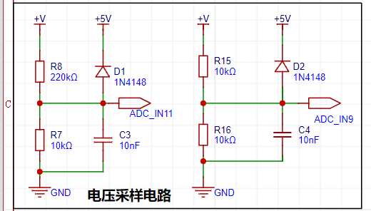 The reference voltage used is 1.5V, and the voltage range of this project is calculated to be 0-30V and 0-5V. Data is read through an ADC, and the voltage of the voltage divider resistor is calculated by comparing it with the reference voltage. The voltage measurement is calculated based on the resistance relationship between the two resistors.
  : Similar to voltage sampling, the voltage is sampled using an ADC, and the obtained value is compared with the 1.5V reference voltage to obtain the voltage of R0, thereby calculating the current in the circuit. Voltage
 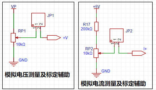 : The voltage and current meters are calibrated by rotating potentiometers JP1 or JP2 to change their resistance values, thereby changing the input voltage or current. An external multimeter can then be connected to calibrate the sampling circuit.

All reference designs on this site are sourced from major semiconductor manufacturers or collected online for learning and research. The copyright belongs to the semiconductor manufacturer or the original author. If you believe that the reference design of this site infringes upon your relevant rights and interests, please send us a rights notice. As a neutral platform service provider, we will take measures to delete the relevant content in accordance with relevant laws after receiving the relevant notice from the rights holder. Please send relevant notifications to email: bbs_service@eeworld.com.cn.
It is your responsibility to test the circuit yourself and determine its suitability for you. EEWorld will not be liable for direct, indirect, special, incidental, consequential or punitive damages arising from any cause or anything connected to any reference design used.
Supported by EEWorld Datasheet
EEWorld
subscription
account

EEWorld
service
account

Automotive
development
community

Robot
development
community

About Us Customer Service Contact Information Datasheet Sitemap LatestNews


Room 1530, 15th Floor, Building B,
No.18 Zhongguancun Street,
Haidian District,
Beijing, Postal Code: 100190
China
Telephone: 008610 8235 0740
 京公网安备 11010802033920号

 SX18AB100-I/TQ


