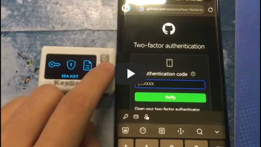
KeyBox-RP2040 Electronic Key:


This is
the source code for an electronic key storage program based on the C language: https://github.com/JasonYANG170/KeyBox-RP2040
Update Log
V1.3:
1. Fixed the power circuit switch control logic.
2. Improve the circuit design diagram, add categories and annotations
. 3. Add the option of independent RTC battery or shared RTC battery. When using a shared battery, please short-circuit the BtR.
Difference between ESP32C3 and RP2040 versions
: The RP2040 version was created after the ESP32C3 version and is a fully localized key storage device. The RP2040 version
has a built-in RTC clock design, eliminating the need for network time synchronization.
The RP2040 version uses USB-HID, eliminating the need for Bluetooth HID connection input.
The RP2040 version package is prone to poor soldering, and is not recommended for beginners. If
the demonstration video
cannot be played, please click here to use BiliBili
functions
: ✅ Supports importing website keys from the browser
✅ Supports TOTP 2FA real-time verification code binding
✅ Supports USB analog input HID
✅ Supports RTC
✅ Supports setting a 6-digit device password
✅ Supports screen off
✅ Supports screen brightness adjustment.
If you encounter any problems, please submit issues to me. This project is licensed under the CC BY-NC-SA 4.0 open-source license. When using this program, please indicate the source and include a copyright notice
. This project is for learning and research purposes only; unauthorized commercial profit is strictly prohibited. If you have any better suggestions, please submit a pull request. If you like this project, please give it a Star ⭐. [Image 1 & 2 of the actual product]


PDF_KeyBox-RP2040.zip
Altium_KeyBox-RP2040.zip
PADS_KeyBox-RP2040.zip
BOM_KeyBox-RP2040.xlsx
92460
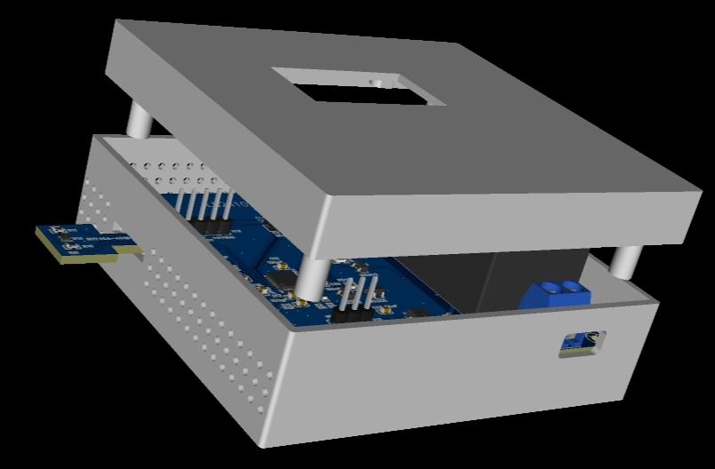
Multi-function lamp controller based on ESP32-C3
This project, based on the ESP32-C3, developed a multi-functional control module for lighting control. It can be connected to Home Assistant to achieve various automated control functions. The project integrates an LD2410 human presence sensor, temperature and humidity sensors, touch sensing, and offline voice functionality.
Project Description:
This project, based on the ESP32-C3, creates a multi-functional control module for lighting. It can be connected to Home Assistant to achieve various automated controls. The project integrates an LD2410 human presence sensor, a temperature and humidity sensor, touch sensing, and offline voice functionality.
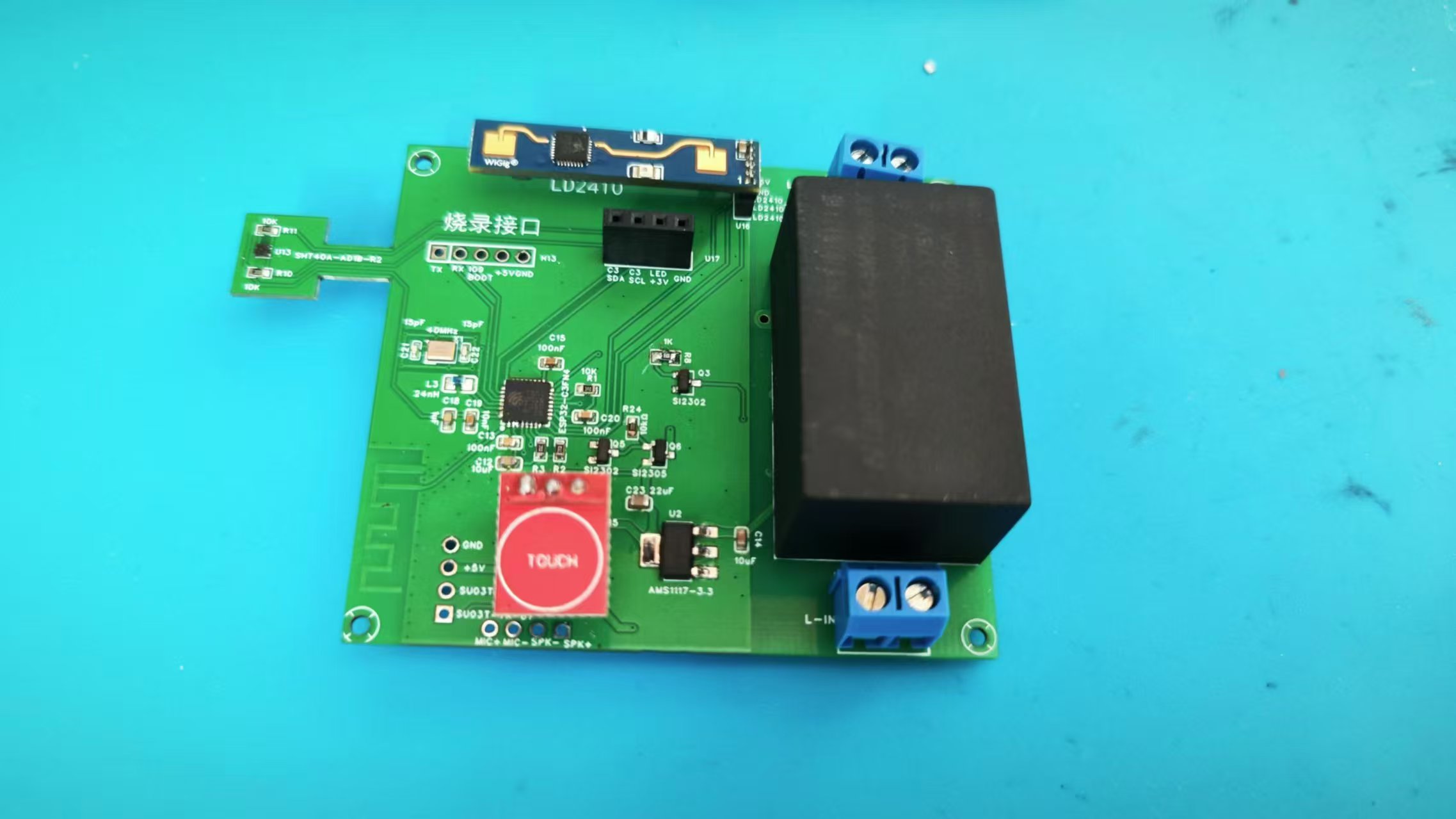
Schematic Design:
Power Supply:

220V; Lights

: SSD1306; Display: Control

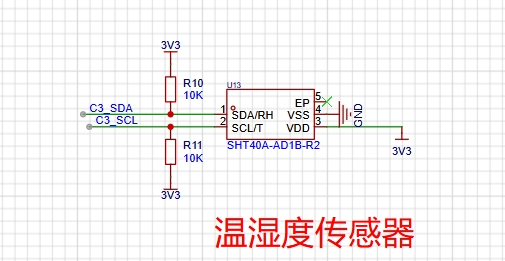
Sensors :
Temperature and Humidity Sensor;
Touch Sensing and Human Presence Sensor;

Offline Voice Function: Main
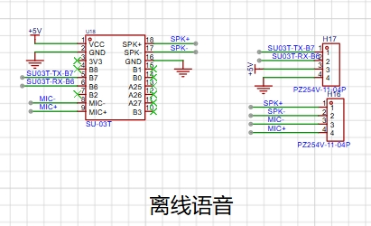
Control Chip:
ESP32-C3;

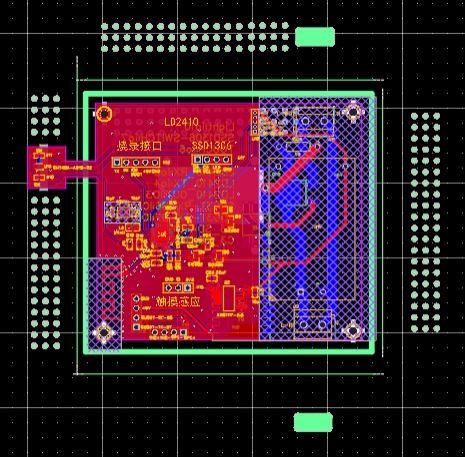
PCB Design:
The temperature and humidity sensor is placed separately on the outside of the casing to prevent heat-generating components from affecting the temperature.
The software part
uses esphome to program c3 and access the homeassistant
code block:
esphome:
name: esp32-c3controler
friendly_name: esp32_c3controler
esp32:
board: airm2m_core_esp32c3
framework:
type: arduino
# Enable logging
logger:
# Enable Home Assistant API
api:
ota:
password: "XXXXXXXXXXXXXXXX"
wifi:
ssid: "XXXXXXXXXXXXXXXX"
password: "XXXXXXXXXXXXXXXX"
# Enable fallback hotspot (captive portal) in case wifi connection fails
ap:
ssid: "Esp32-C3Controler"
password: "h8OEhLousCaS"
captive_portal:
font:
- file: "fonts/ZhuqueFangsong.ttf"
id: ch_font
size: 22
glyphs: Hello temperature is wet!"%()+,-_.:°0123456789ABCDEFGHIJKLMNOPQRSTUVWXYZ abcdefghijklmnopqrstuvwxyz
- file: "fonts/simkai.ttf"
id: time_font
size: 28
- file: "fonts/simkai.ttf"
id: my_font3
size: 18
# Example configuration entry
i2c:
sda: GPIO19
scl: GPIO18
image:
- file: mdi:home-thermometer-outline
id: temp
resize: 30x30
- file: mdi:water-percent
id: hum
resize: 30x30
- file: mdi:white-balance-sunny
id: sunny
resize: 30x30
- file: mdi:weather-partly-cloudy
id: cloudy
resize: 30x30
- file: mdi:weather-rainy
id: rainy
resize: 30x30
- file: mdi:weather-pouring
id: pouring
resize: 30x30
time:
- platform: homeassistant
id: esptime
uart:
- id: ld24100
tx_pin: GPIO5
rx_pin: GPIO4
baud_rate: 256000
parity: NONE
stop_bits: 1
# - id: uart_bus_cmd
# rx_pin: GPIO10 # Modify according to your wiring, eg, D6
# baud_rate: 9600
# text_sensor:
# - platform: custom
# lambda: |-
# auto my_custom_sensor = new UartReadLineSensor(id(uart_bus_cmd));
# App.register_component(my_custom_sensor);
# return {my_custom_sensor};
# text_sensors:
# name: "c3-controler"
# id: "c3controler"
# # update_interval: 5s
# on_value:
# then:
# - delay: 5s
# - lambda: |-
# id(c3controler).publish_state("abc");
ld2410:
binary_sensor:
- platform: gpio
pin:
number: GPIO3
inverted: false
mode: INPUT
name: "2410motion-out"
device_class: motion
- platform: ld2410
has_target:
name: Presence
has_moving_target:
name: Moving Target
has_still_target:
name: Still Target
out_pin_presence_status:
name: out pin presence status
- platform: gpio
pin:
number: 6
mode:
input: true
pullup: true
name: "C3-TOUCH"
filters:
- delayed_on_off: 50ms #This is essential; it acts as a filter.
# Set GPIO10 as an output pin to control the light
output:
- platform: gpio
pin: GPIO10
id: gpio_output
inverted: false
# Define a light that uses the GPIO10 pin defined above
light:
- platform: binary
name: "c3-light"
output: gpio_output
switch:
- platform: gpio
pin: GPIO7
name: "ssd1306-switch"
id: ssd1306switch
restore_mode: RESTORE_DEFAULT_ON
sensor:
- platform: sht4x
temperature:
name: "Temperature"
humidity:
name: "Relative Humidity"
- platform: ld2410
light:
name: light
moving_distance:
name : Moving Distance
still_distance:
name: Still Distance
moving_energy:
name: Move Energy
still_energy:
name: Still Energy
detection_distance:
name: Detection Distance
g0:
move_energy:
name: g0 move energy
still_energy:
name: g0 still energy
g1:
move_energy:
name: g1 move energy
still_energy:
name: g1 still energy
g2:
move_energy:
name: g2 move energy
still_energy:
name: g2 still energy
g3:
move_energy:
name: g3 move energy
still_energy:
name: g3 still energy
g4:
move_energy:
name: g4 move energy
still_energy:
name: g4 still energy
g5:
move_energy:
name: g5 move energy
still_energy:
name: g5 still energy
g6:
move_energy:
name: g6 move energy
still_energy:
name: g6 still energy
g7:
move_energy:
name: g7 move energy
still_energy:
name: g7 still energy
g8:
move_energy:
name: g8 move energy
still_energy:
name: g8 still energy
- platform: homeassistant
id: temperature
entity_id: sensor.miaomiaoce_t2_b84f_temperature_humidity_sensor
internal: true
- platform: homeassistant
id: humidity
entity_id: sensor.miaomiaoce_t2_b84f_relative_humidity
internal: true
- platform: homeassistant
id: current_weather
entity_id: weather.he_feng_tian_qi
attribute: condition_cn
- platform: homeassistant
id: update_time
entity_id: weather.he_feng_tian_qi
attribute: update_time
- platform: homeassistant
id: day1_forecast
entity_id: weather.he_feng_tian_qi
attribute: daily_forecast[0].text
display:
- platform: ssd1306_i2c
model: "SSD1306 128x64"
address: 0x3C
id: my_display
# lambda: |-
# if (id(adcin).has_state()) {
# it.printf(90, 10, id(ch_font), TextAlign::TOP_CENTER , "%.4f", id(adcin).state);
# }
pages:
- id: showtime
lambda: |-
it.strftime(60, 40, id(time_font), TextAlign::BASELINE_CENTER, "%H:%M:%S", id(esptime).now());
- id: show_tem_hum
lambda: |-
if (id(temperature).has_state()) {
it.printf(90, 10, id(ch_font), TextAlign::TOP_CENTER , "%.1f°C", id(temperature).state);
it.image(20, 10, id(temp));
}
if (id(humidity).has_state()) {
it.printf(90, 40, id(ch_font), TextAlign::TOP_CENTER , "%.1f%%", id(humidity).state);
it.image(20, 40, id(hum));
}
interval:
- interval: 2s
then:
- display.page.show_next: my_display
- component.update: my_display
Physical display instructions
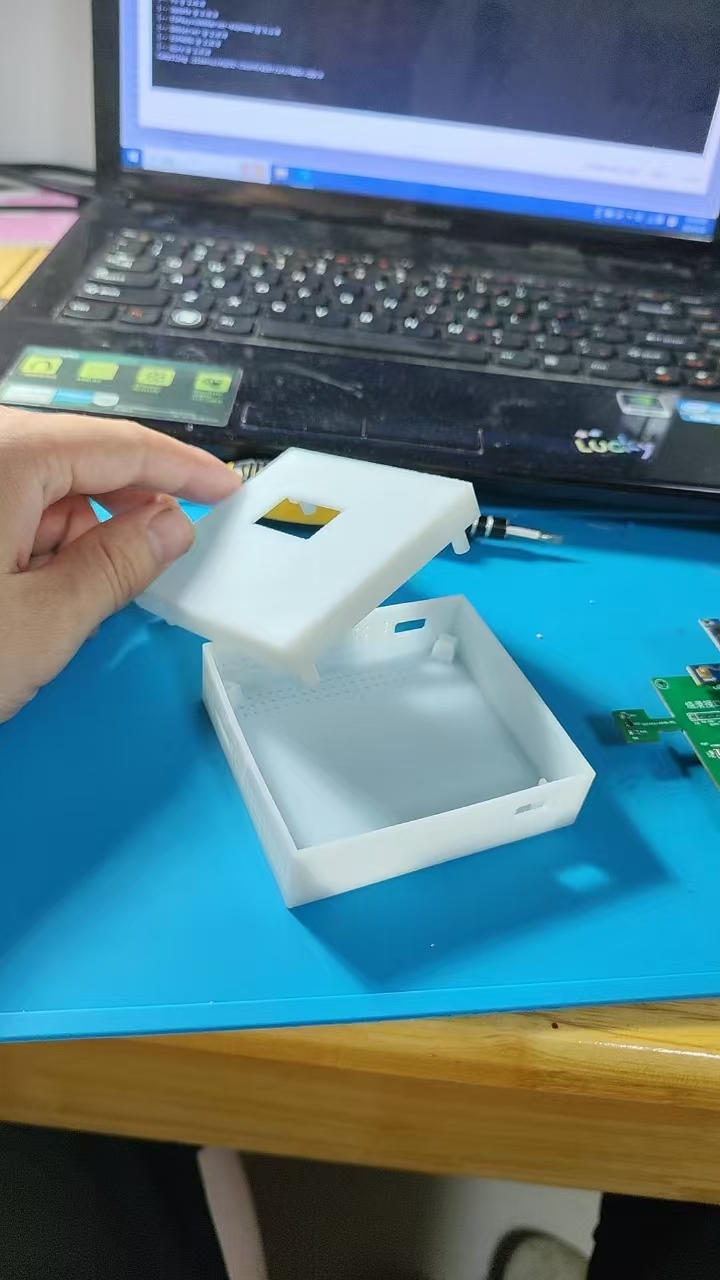

and precautions
: This project involves high-voltage electricity, please handle with caution!
637dcca42346cfb1a9cadd9af294f1fa.mp4
PDF_Multi-in-one lamp controller based on ESP32-C3.zip
Altium_All-in-One Light Controller Based on ESP32-C3.zip
PADS_multi-function single lamp controller based on ESP32-C3.zip
BOM_Multi-in-one lamp controller based on ESP32-C3.xlsx
92461
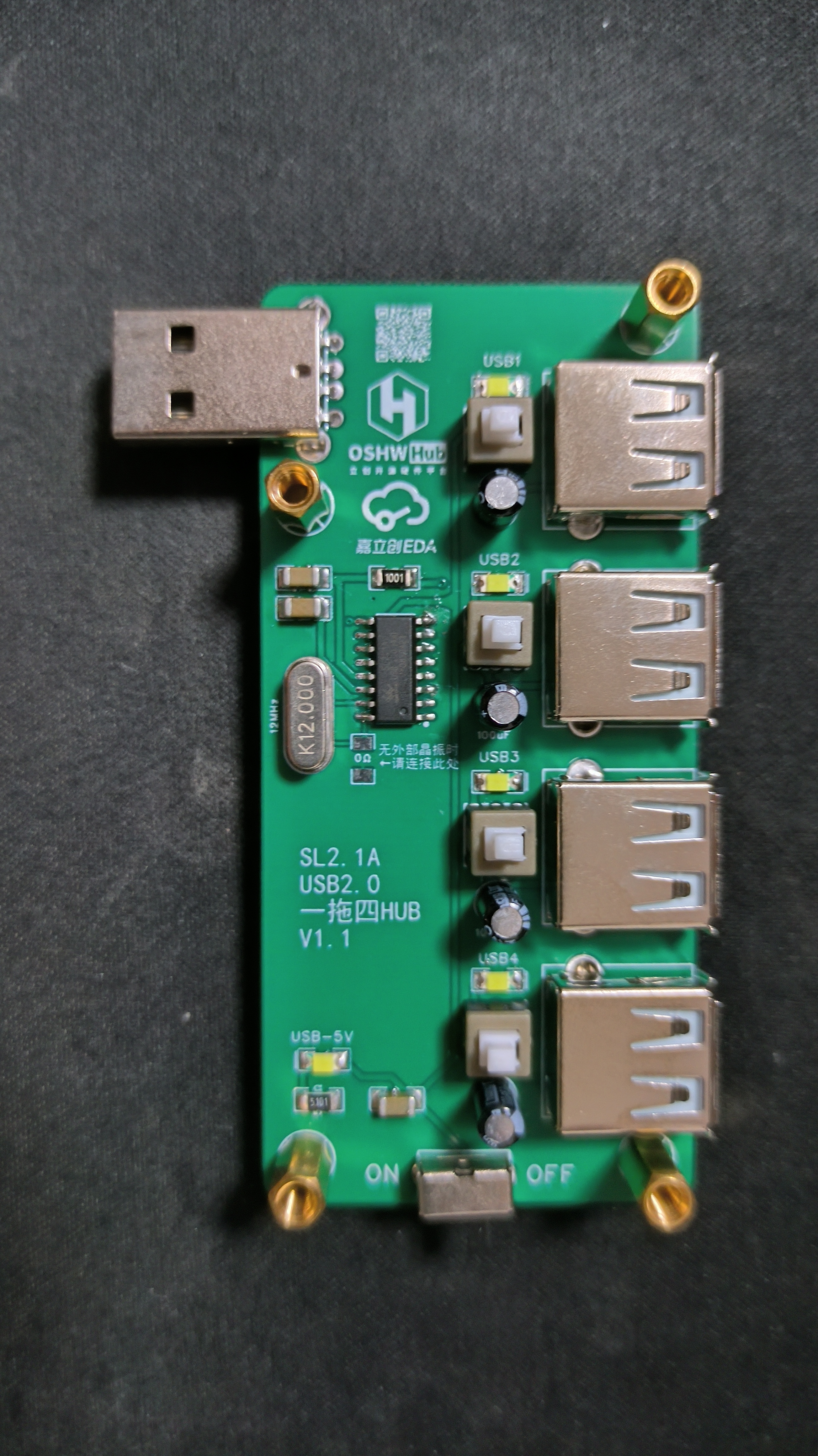
4-port USB 2.0 HUB based on SL2.1A
Replicating open-source examples from the community, many components are sourced from LCSC (a major electronics retailer) where coupons are available.
PDF_SL2.1A-based 4-port USB 2.0 HUB.zip
Altium_SL2.1A-based 4-port USB 2.0 HUB.zip
PADS_SL2.1A-based 4-port USB 2.0 HUB.zip
BOM_SL2.1A-based 4-port USB 2.0 HUB.xlsx
92462
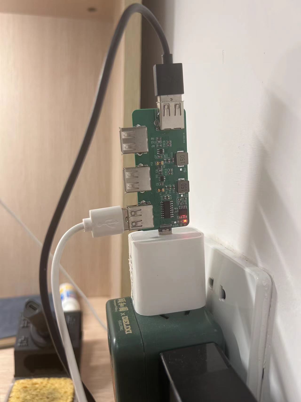
High-power expansion dock integrating fast charging protocols
This device integrates the CH224K, TPS54202, and SL2.1A chips, which not only expands the USB ports but also utilizes fast charging spoofing and buck technology to provide a stable power output of up to 20W. Its design combines power supply and data transfer capabilities, making it suitable for everyday use and high-power applications.
1. Project Overview
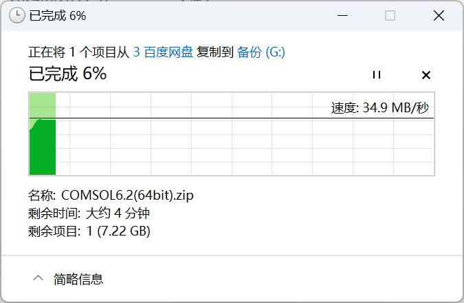
Traditional docking stations only support 5V, 500mA output, which can easily lead to insufficient power supply when driving devices exceeding 2.5W. Therefore, this project integrates fast charging technology on the basis of a regular docking station to improve the power supply problem. Specifically, the power supply section of this device adopts a CH224 (fast charging decoy) and two TPS54202 (DC-CDC 5V step-down) architecture. Meanwhile, the data section uses the SL2.1A chip, which also functions as a docking station, meeting the needs of high power and data transmission. After testing, the total output power of the power supply expansion interfaces reached 20W, and the maximum data transmission rate reached 34.9Mb/s.
2. Block Diagram
2.1 Power Supply Section

Figure 1 shows a schematic diagram of the power supply section. The `CH224K` is connected to the charger via the `CC` cable, and the charger's output voltage is stepped down to `5V` by the `TPS54202`.
2.2 Data Section

The data section expands to 4 channels via USB D+ and D-.
3. Principle Analysis
3.1 Power Supply Principle Analysis
3.1.1 Fast Charging Protocol
The mainstream fast charging protocols include QC and PD. The QC protocol uses the USB D+ and D- lines, while the PD protocol uses the CC line. The CH224 supports both protocols. Since the D+ and D- lines are used for data expansion, this paper uses the QC protocol for spoofing in the power supply section. This is achieved by connecting the CC1 and CC2 of the Type-C male connector to the CC line of the CH224 chip. The CH224's CFG1 is connected to GND with resistor R11, and different resistance values correspond to different voltage request levels. The specific table is as follows:
Resistor
Request Voltage
6.8KΩ
9V
24KΩ
12V
56KΩ
15V
NC
20V
The specific voltage that can be spoofed depends on the capability of the fast charging device itself. If the device's maximum voltage is only 12V, then even if configured for 20V, only the highest 12V output can be requested.
3.1.2 TPS54202 Step-Down Chip
The TPS54202 step-down chip supports 4.5V-28V input. R11 is set to 24K, induced at 12V.
The maximum voltage of the PD3.0 protocol is 20V, so R11 can be omitted (but note that the withstand voltage of C2 and C8 should be above 20V). The voltage is directly induced based on the maximum output voltage of the charging head. The design of the step-down circuit and PCB layout both refer to the datasheet.
4. Usage Method
4.1 High-Power Expansion
After plugging the device into the charging head, this device can expand the charging head to 4 outputs. Without fast charging protocol support, each output supports 5V/0.5A; when fast charging protocol is activated, it provides the corresponding output power according to the load demand to meet the needs of high-power devices.
4.2 Ordinary Expansion Dock
After plugging the device into the computer, the device can be used as an ordinary expansion dock, conveniently connecting peripherals such as mice, keyboards, and USB flash drives. The data transfer rate can reach 34.9Mb/s, meeting daily usage needs.
5. Precautions:
Capacitors C14 and C15 must be soldered; otherwise, the expansion dock function in the data section will not work properly.
Pin 11 of the CH224 chip (similar to a heatsink pad) must be connected; otherwise, fast charging cannot be triggered.
It is recommended to choose a PCB thickness of 1.0mm when fabricating the board; otherwise, the Type-C interface may not be able to be inserted.

6. Attached Files:
High-Power Expansion Dock BOM - LCSC_20240904.xls
Datasheet,
High-Power Expansion Dock Gerber File (for direct board fabrication),
High-Power Expansion Dock PCB
High-Power Expansion Dock BOM - LCSC_20240904.xls
Datasheet.zip
High-power expansion dock Gerber.zip
High-power expansion dock PCB.zip
PDF_High-Power Expansion Dock with Integrated Fast Charging Protocol.zip
Altium_High-Power Expansion Dock with Integrated Fast Charging Protocol.zip
PADS_High-Power Expansion Dock with Integrated Fast Charging Protocol.zip
BOM_High-Power Expansion Dock with Integrated Fast Charging Protocol.xlsx
92463
ESP32 Bluetooth remote control car
The ESP32 Bluetooth remote control car can be controlled via a mobile app and its functions are expandable.
The physical demonstration
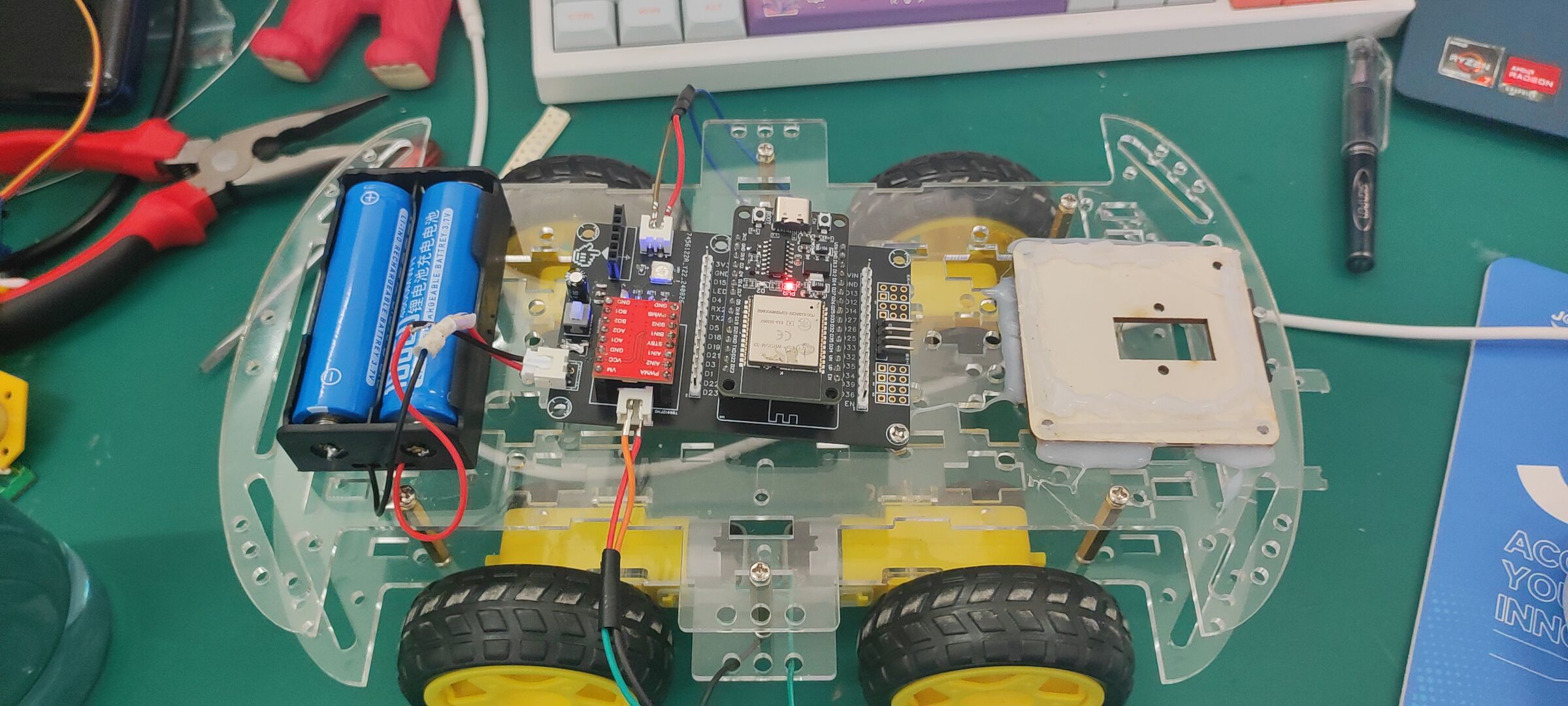
uses an ESP32 module as the main controller and
a TB6612FNG motor drive module. It
communicates with a mobile phone via Bluetooth through the ESP32 and
controls the car's movement via a mobile app. The car
includes a motion status indicator light, a buzzer,
and can be expanded with ultrasonic sensors, servos, cameras, etc.
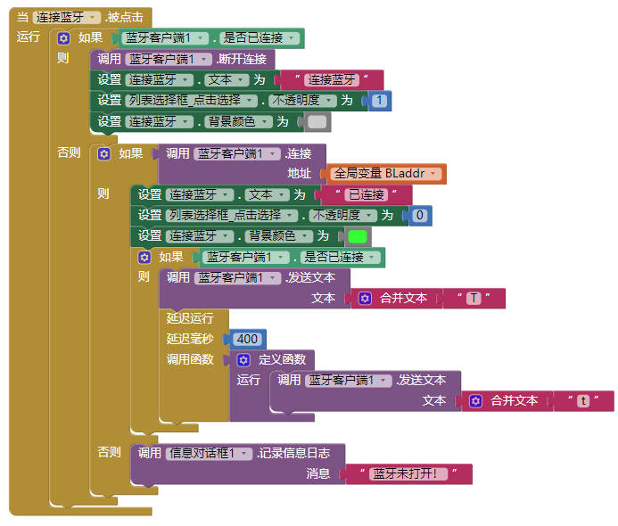
2. Key code:
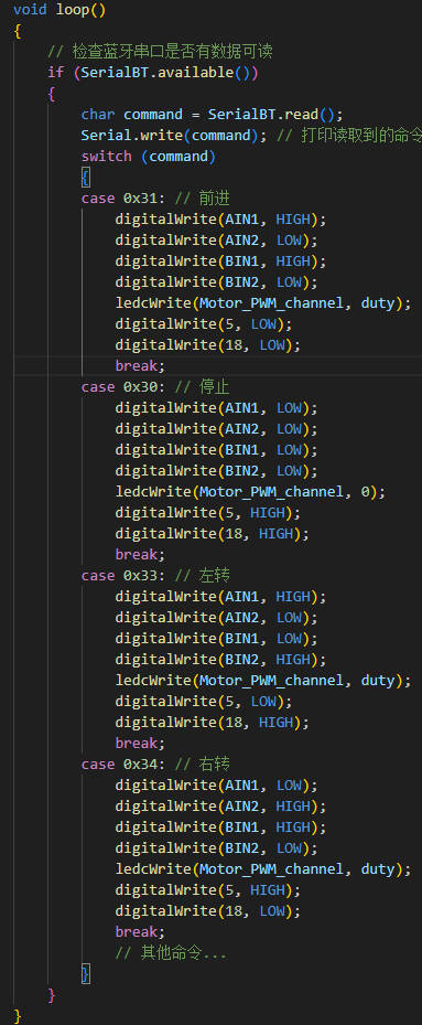
Mobile app section:
app interface
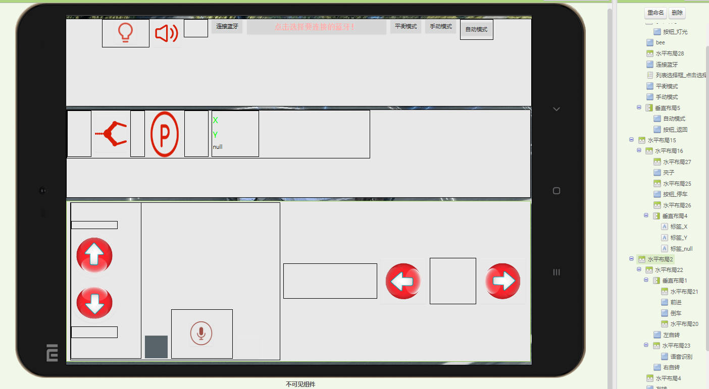
, button control,

Bluetooth connection.
Demo video.mp4
ESP32_BLCar.zip
VoiceBLCar.apk
Demo video.mp4
PDF_ESP32 Bluetooth Remote Control Car.zip
Altium_ESP32 Bluetooth Remote Control Car.zip
PADS_ESP32 Bluetooth Remote Control Car.zip
BOM_ESP32 Bluetooth Remote Control Car.xlsx
92464
electronic


 京公网安备 11010802033920号

 CCL225DE2-A


