Project Introduction,
Design Background and Purpose: This project aims to help learners master electronic measurement principles and technologies such as microcontroller circuit design and implementation, signal acquisition and processing circuit design, user interface development and optimization, and product appearance design by designing and building a digital voltmeter and ammeter.
Project Features:
Combining core board and expansion board design concepts, this project uses plug-in device design for easy learning and in-depth exploration.
It uses the domestic chip software library CW32F030C8Tx as its core, compatible with other similar microcontrollers.
The project has a high degree of integration and practicality; after completion, it can be used as a desktop instrument.
It provides abundant learning materials, including circuit design tutorials, PCB design, code programming, and training in engineer debugging skills.
Hardware Design: Covering multiple key parts such as power supply circuit, MCU selection, voltage sampling, current sampling, and digital tube display, ensuring the project's comprehensiveness and practicality.
Software Control: Implementing dynamic scanning display drive for the digital tube, providing accurate voltage and current measurement display.
Function Introduction
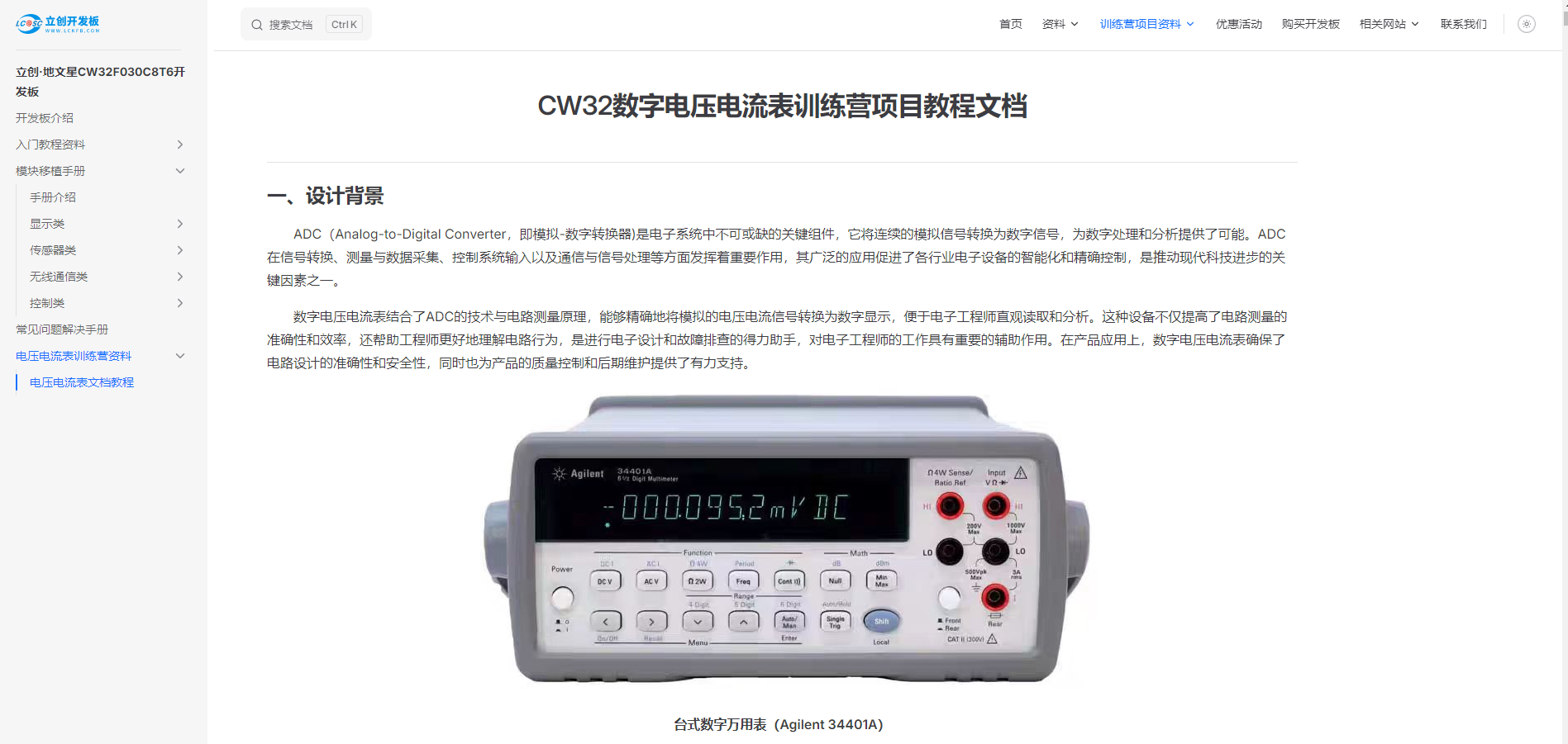
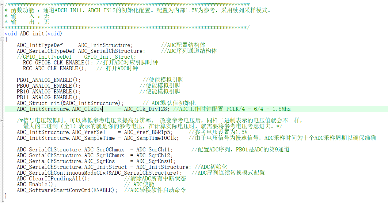
: Voltage Measurement: Through the built-in high-precision ADC (analog-to-digital converter) and voltage sampling circuit, it can accurately measure and display voltage values.
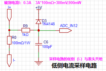
Current Measurement: Utilizing a low-side current sampling circuit, it accurately measures and displays current values. The maximum designed sampling current is 3A, and a 100mΩ resistor is used as the current sensing resistor.
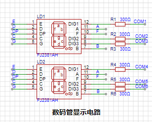
Digital Display: Two 0.28-inch three-digit common-cathode digital tubes are used as display units, with dynamic scanning display drive, providing good readability and mechanical performance.
LED Indicators: Includes power indicator and I/O indicator, intuitively displaying device status.
Button Control: A button circuit is designed for convenient user interaction.
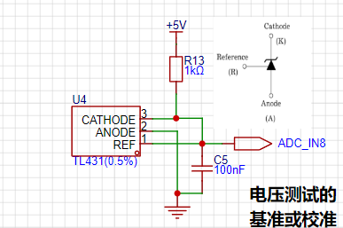
TL431 Reference Voltage Circuit: Provides a 2.5V reference voltage for ADC calibration, ensuring measurement accuracy.
Power Supply Circuit: Employs an LDO (Low Dropout Linear Regulator) design, supporting wide voltage input up to 40V, suitable for industrial applications.
MCU Core: The project's core is based on the domestically developed CW32F030C8Tx microcontroller software library, providing powerful processing capabilities and rich peripheral support.
The hardware design
primarily references the "CW32 Digital Voltage and Current Meter Training Camp Project Tutorial Document," which is extremely detailed, down to the selection of each component—a truly excellent document!
1. Schematic Diagram Explanation:
Power Supply Circuit
: Power input: Connected to the power supply via a DC interface or VP.
LDO Selection: SE8550K2 is selected as the power regulator to ensure stable 5V output.
Circuit Protection: Reverse connection and overcurrent protection are provided using a Schottky diode 1N5189 and a 10Ω resistor.

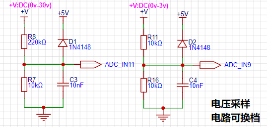
Voltage Sampling Circuit
Design Principle: Voltage measurement is performed using a voltage divider resistor, with a maximum range designed to be 30V.
Circuit Protection: A clamping diode 1N4148 is used to protect the ADC pins.
Current Sampling Circuit
Design Principle: Current is calculated by measuring the voltage drop across the sampling resistor, using a 100mΩ resistor to reduce interference to the circuit under test.
Circuit Protection: Current-limiting resistors and clamping diodes are used to protect the MCU pins.
Analog Sampling and Calibration
Circuit: Voltage Sampling: A TL431 is used to provide a 2.5V reference voltage for calibration.
Current Sampling: Analog current measurement circuit design to ensure accurate measurement range.
Other Circuits: Digital
Tube Display: Use common cathode digital tubes to display measurement results.
Buttons and LED Indicators: Design three-button function control and status indicator LEDs.

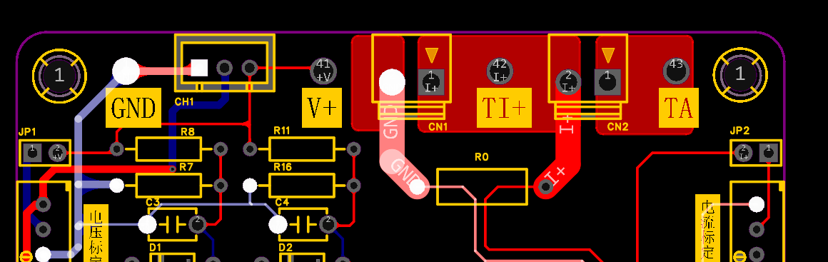
2. PCB Layout and Soldering Considerations
Line Width Requirements
Power Lines: 20-60mil
Signal Lines: 10mil
ADC Signal Lines: 8mil or 10mil
Soldering Considerations
Capacitors and Diodes: Pay attention to polarity.
Digital Tubes: Avoid high-temperature contact.
Software Design
1. Software Architecture
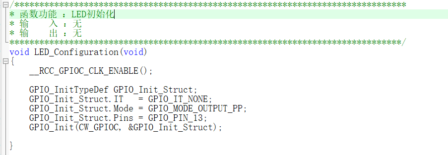
Basic Modules: Clock Configuration, GPIO Initialization.
Core Modules: BTIM Interrupt Control, ADC Analog-to-Digital Conversion.
Peripheral Modules: LED Driver, Digital Tube Driver, Button Driver.
Auxiliary Modules: Data Storage and Data Processing.
2. Module Brief Description
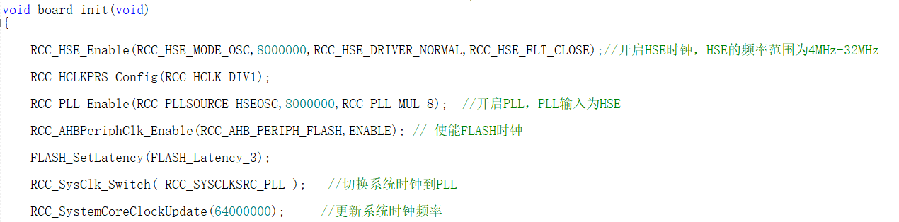
RCC Clock Configuration
Configures the system clock to support the clock requirements of each functional module.
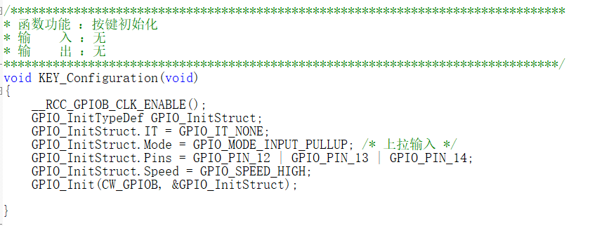
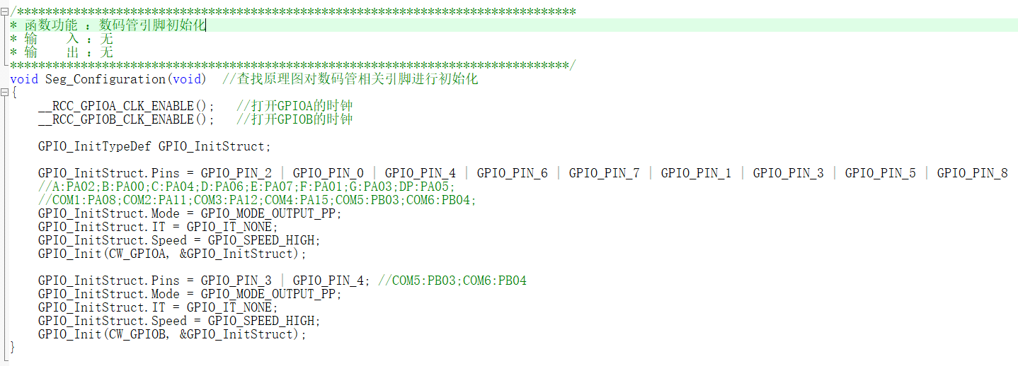
GPIO Configuration
Initializes peripherals such as LEDs, buttons, and digital tubes.
ADC Module
Configures ADC pins and uses mean filtering to stabilize data.

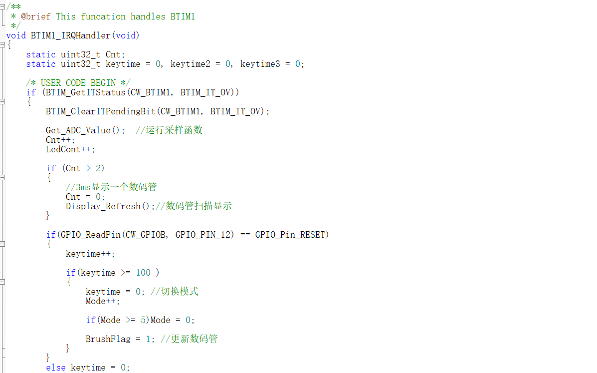
BTIM Control Interrupt Module
Periodically acquires ADC data, updates the display, and processes button operations.
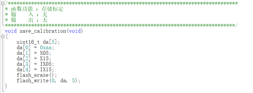
The digital tube driver module
implements data encoding and dynamic display;
the FLASH storage module
implements the storage and calculation of calibration parameters.

3. Other modules
: A debugging module facilitates environment configuration and circuit verification during the development phase.
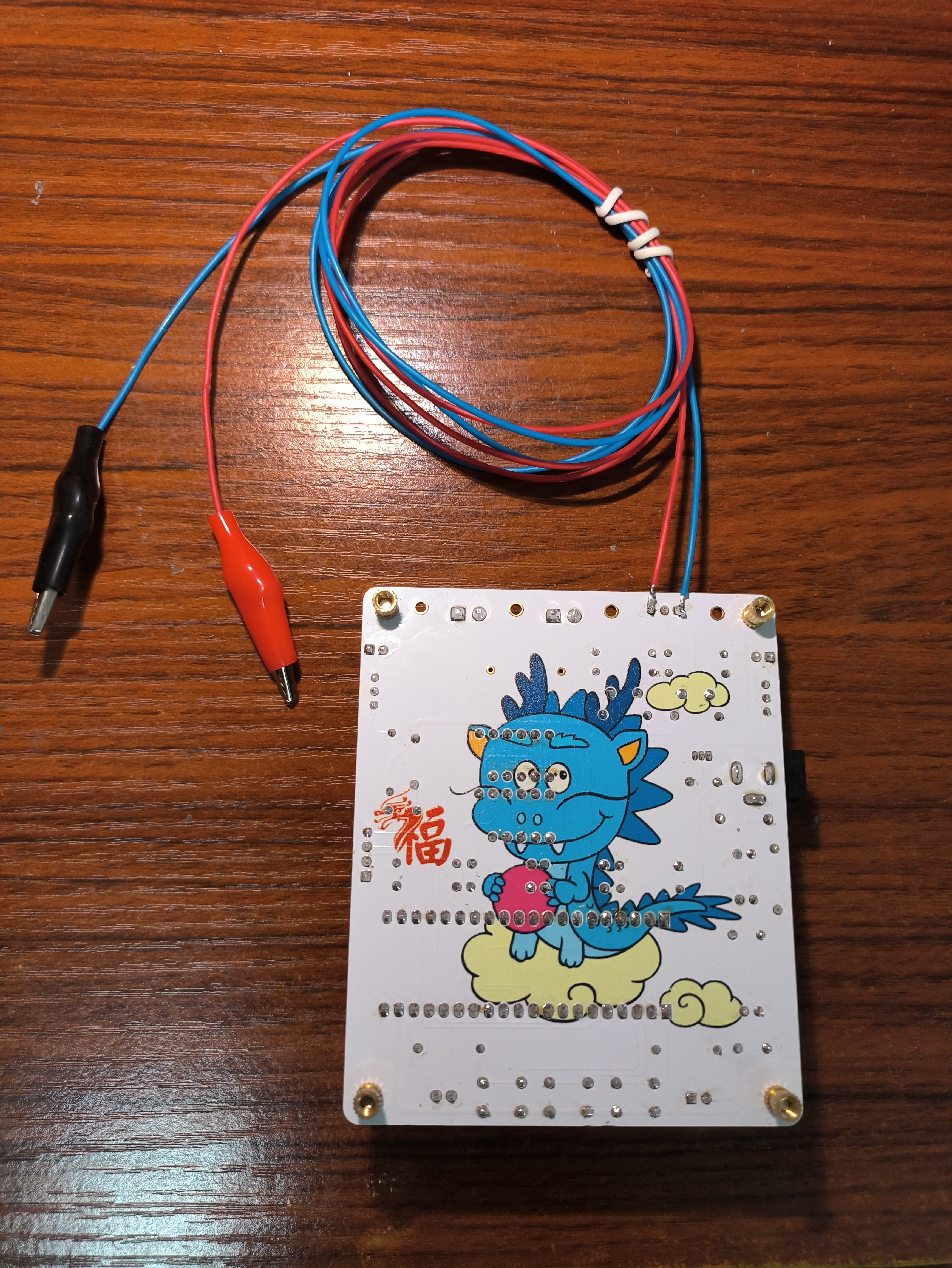
Physical product image
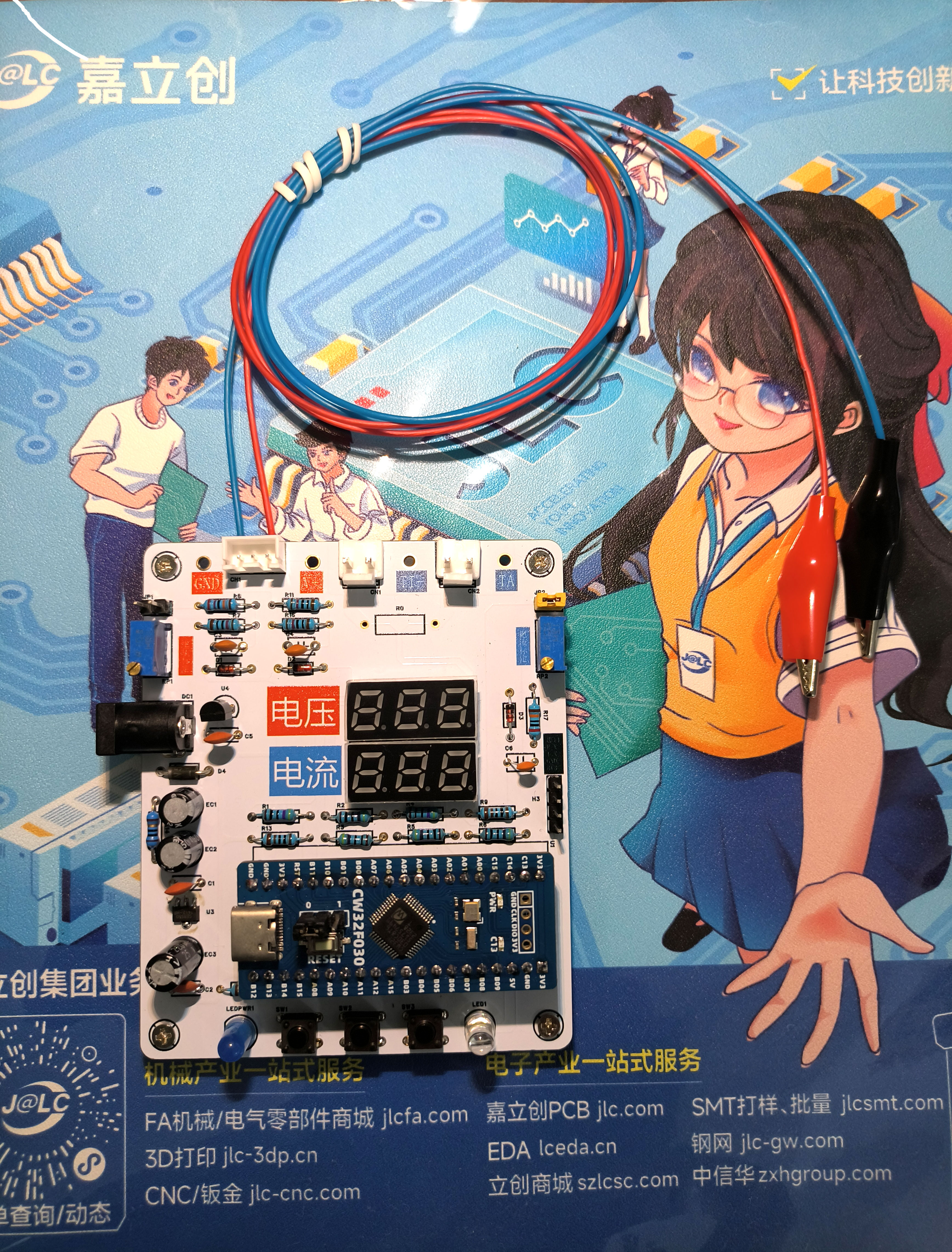
: Front: Color silkscreen printing

; Back: Cute baby dragon.
Video demonstration
: https://www.bilibili.com/video/BV1UapoeoErT/


 京公网安备 11010802033920号

 4CS065-01TG


