#LCSC Training Camp#
Because I really wanted to build a drone myself, but as a complete beginner, I had absolutely no knowledge of electronic circuit hardware and software, so I joined the #LCSC Training Camp# to accumulate knowledge. (Since this is my first time doing this, please give me your feedback on any shortcomings.)
I. Hardware The
hardware part referenced the "CW32 Digital Voltmeter and Ammeter Training Camp Project Tutorial Document"; I changed the through-hole components to surface-mount components. Every step in the document is very detailed, making it easy for beginners to learn without having to search for tutorials everywhere. I really love it! LCSC is awesome!!!

1. Power Supply Circuit
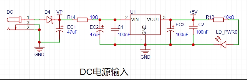
This project uses a low-cost LDO low-dropout linear regulator as the power supply.
2. Main Controller:

This project uses the LCSC CW32F030C8Tx development board (core board) as the main controller.
Advantages of the CW32:
- Wide operating temperature range: -40~105℃
- Wide operating voltage range: 1.65V~5.5V
- Strong anti-interference: HBM ESD 8KV, all ESD reliability reaches the highest international standard level
- Key focus of this project - Better ADC: 12-bit high-speed ADC, achieving ±1.0LSB INL 11.3ENOB, multiple Vref reference voltages... ...
- Stable and reliable eFLASH technology.
3. Voltage Sampling Circuit:

The voltage divider resistors used in this circuit are 220K+10K.
Voltage Divider Resistor Selection
: 1. Maximum design measurement voltage: For safety reasons, this project uses 30V (actual maximum display can be 99.9V or 100V);
2. ADC reference voltage: This project uses 1.5V, which can be configured through the program;
3. Power consumption: To reduce the power consumption of the sampling circuit, the low-side resistor (R7) is usually selected as 10K based on experience;
then the high-side resistance of the voltage divider resistor can be calculated using the above parameters:
1. Calculate the required voltage division ratio: i.e., ADC reference voltage: design input voltage, which can be calculated using known parameters as 1.5V/30V=0.05
2. Calculate the high-side resistance: i.e., low-side resistance/voltage division ratio, which can be calculated using known parameters as 10K/0.05=200K
3. Select a standard resistor: Select a resistor slightly higher than the calculated value, which is 200K. We usually choose E24 series resistors, so in this project, we choose 220K, which is greater than 200K and closest to it.
4. Current Sampling Circuit:

The sampling current designed for this project is 3A, and the selected sampling resistor (R0) is 100mΩ.
The following aspects should be considered when selecting the sampling resistor:
1. The maximum value of the pre-designed measurement current, which is 3A in this project
. 2. The voltage difference caused by the current sensing resistor; it is generally not recommended to exceed 0.5V.
3. The power consumption of the current sensing resistor; a suitable package should be selected based on this parameter. Considering the power consumption (temperature) issue under high current, a 1W metal wire-wound resistor was selected in this project.
4. The voltage amplification factor across the current sensing resistor: No operational amplifier is used to build the amplification circuit in this project, so the factor is 1.
The current sensing resistor value can then be calculated using the above parameters.
1. Since this project does not use an amplifier circuit, a larger sampling resistor is needed to obtain a higher measured voltage for measurement.
2. Considering that a larger resistor will result in a larger voltage drop and higher power consumption, an unlimited selection of a larger resistor is not advisable.
3. This project uses a 1W package resistor, corresponding to a power consumption of 1W. Based on
the above data, a 100mΩ current-sensing resistor was selected. According to the formula, 3A * 100mΩ = 300mV, 900mW can be calculated.
5. Display Unit:
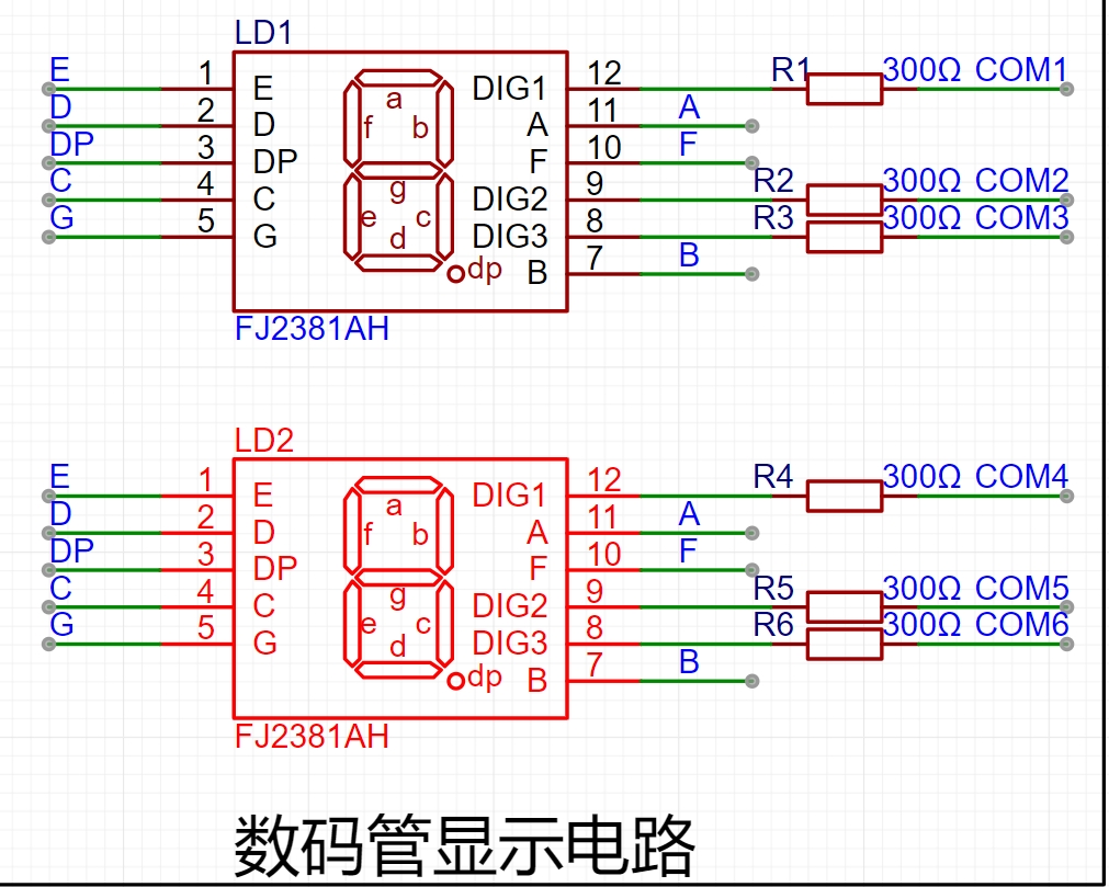
This project uses two simpler and more stable three-digit common-cathode LED displays as the display device.
In this project, the current-limiting resistors (R1~R6) of the LED displays are configured to 300Ω. The corresponding brightness, whether for red or blue LED displays, has good visibility and is soft and not dazzling.
6. Status Indicators:
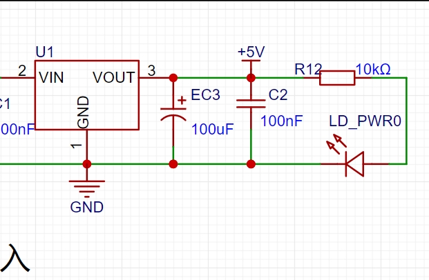
LD_PWR0 is the power indicator ,

and LED1 is the working indicator.
To reduce the current consumption of the LEDs, some LED brightness is sacrificed, and the number of device parameters is reduced. The current-limiting resistor for the LEDs is selected as 10K.
7. Button Control Circuit

The button control circuit can be designed in various ways. Thanks to the CW32's internal I/O ports which can be configured with pull-up and pull-down resistors, the button control circuit on the outside of the chip does not need to be configured. One end of the button is connected to the MCU's I/O, and the other end is grounded. When the button is pressed, the I/O is pulled low.


 京公网安备 11010802033920号

 ATS145-89R8-BB452Q


