

Project Overview:
This project is an open-source project from the LCSC Voltage and Current Meter Training Camp. Based on the LCSC CW32 development board, it's an expansion board design for a voltage and current meter, capable of detecting externally input voltage and current. Theoretically, the voltage range is 0-100V, and the current range is 0-3A.
Project Parameters
: Voltage range: 0-100V (not recommended to exceed 30V for safety);
Current range: 0-3A; The current sensing resistor can be adjusted or replaced with an amplifier to increase the range;
6-36V input, standard DC interface, LDO power supply system, nominal value 12V;
Three buttons, events can be customized according to the program;
The design includes an adjustable reference voltage for quick testing and calibration.
LED power indicator and operation indicator physical verification
: Voltage verification:
I only have a small USB adjustable voltage source on hand, so I used it with a power bank for testing;
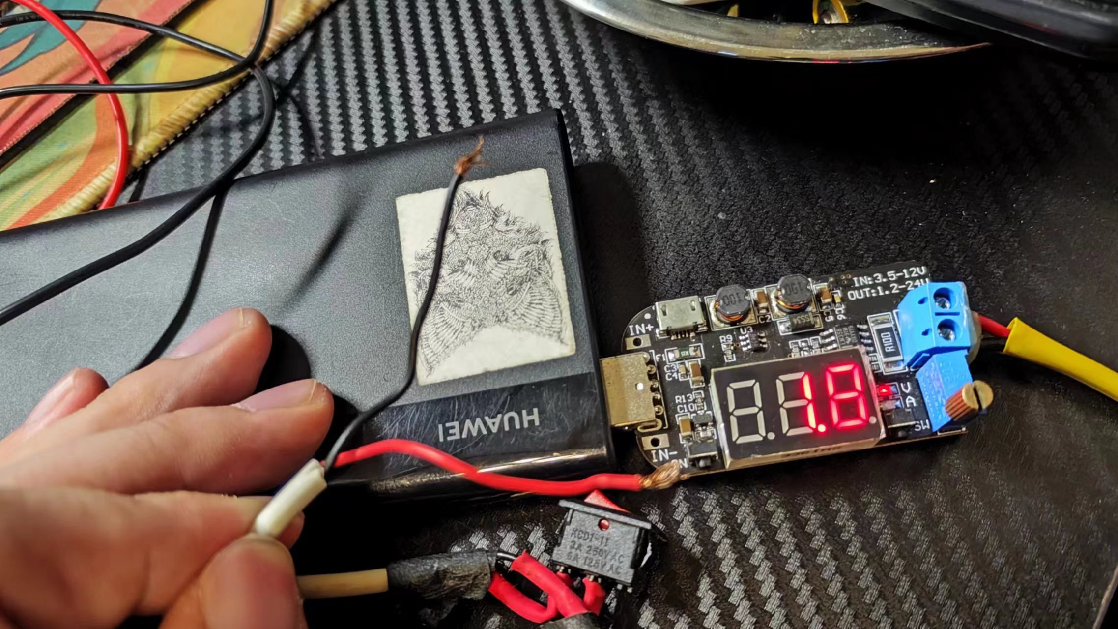
because this small USB voltage source costs only a few dollars and the reading is inaccurate, we used a regular multimeter as a reference;
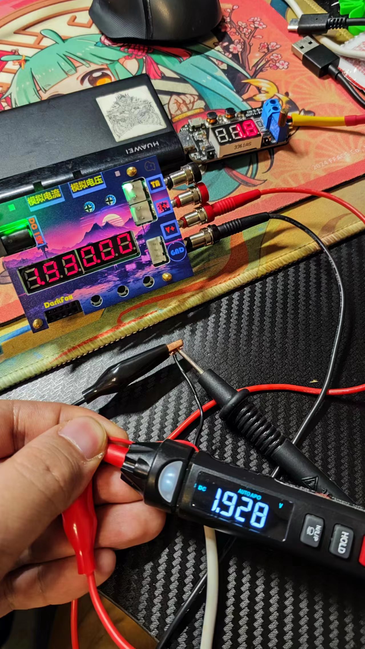
after connecting the cables, we can see that the readings are basically consistent;
Current verification:
I don't have a current source on hand, so I used a voltage source and an LED to form a rough constant current source; under low current conditions, the accuracy of this USB power source is slightly higher, because my cheap multimeter doesn't have a current measurement mode, so I used this as a rough reference; we can see that the parameters are basically consistent;
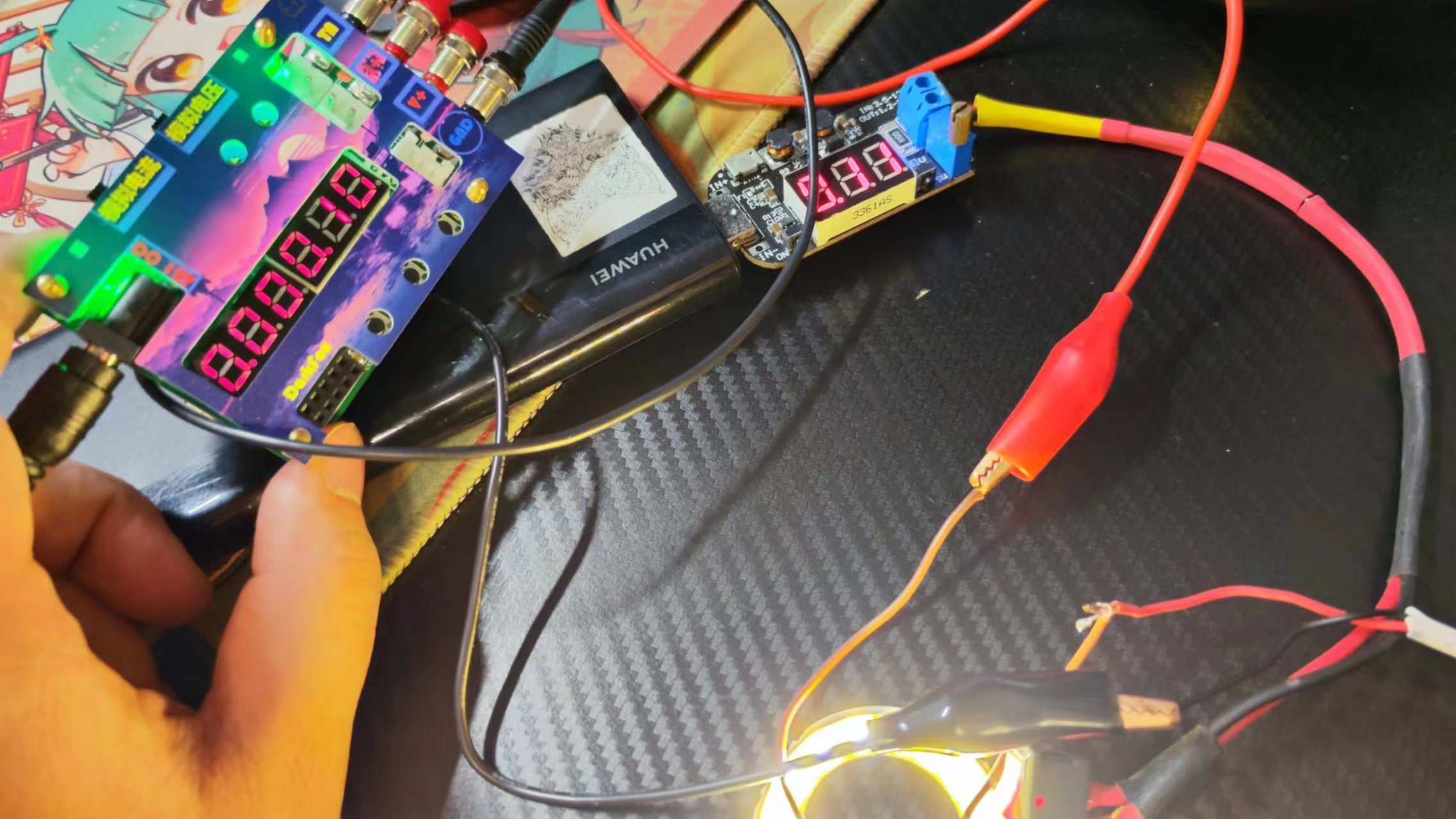
verification is now complete;
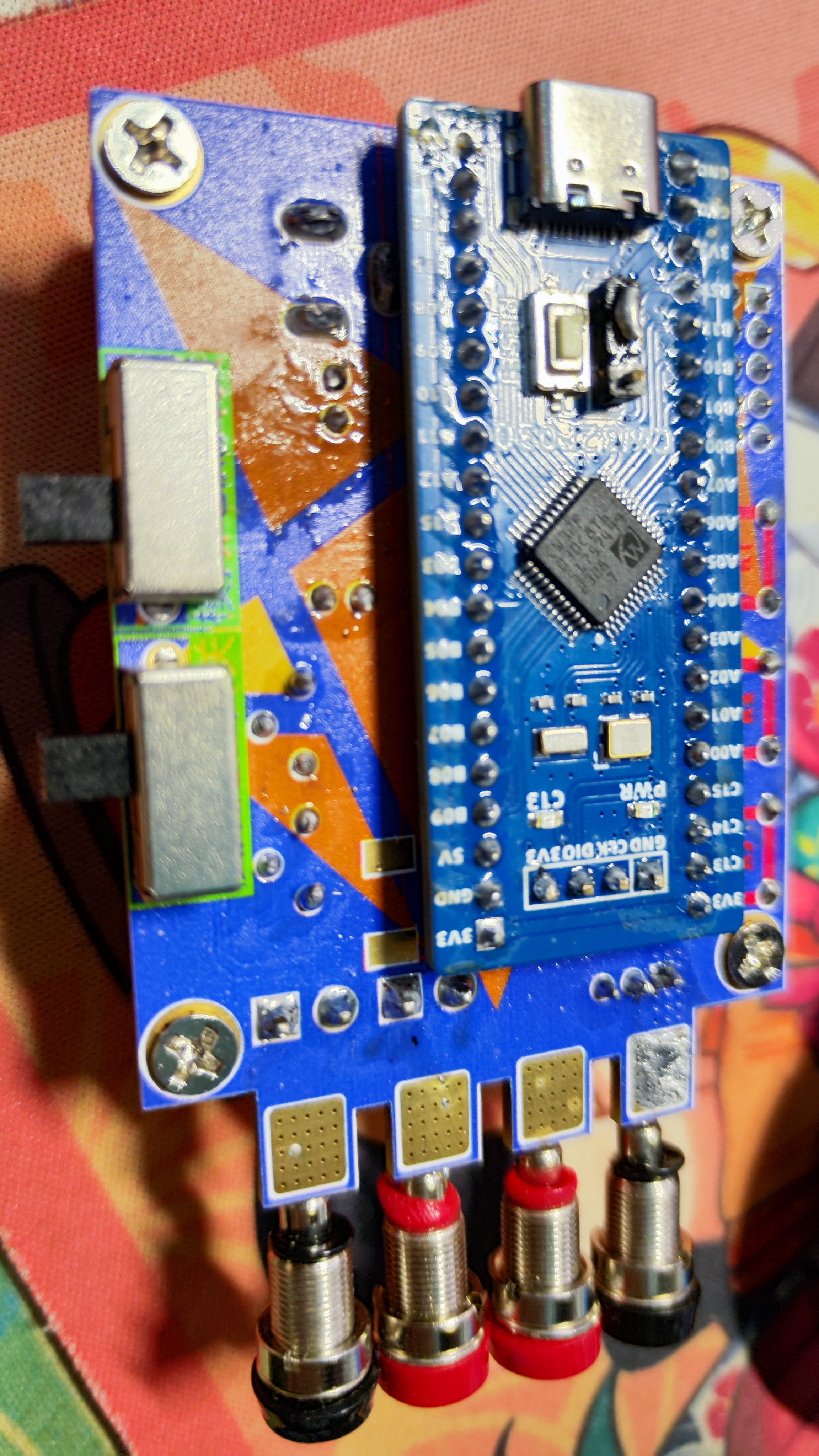
Hardware design
1. Power supply circuit A
suitable power supply is the solid foundation of a good circuit, and choosing a good power supply system is very important;
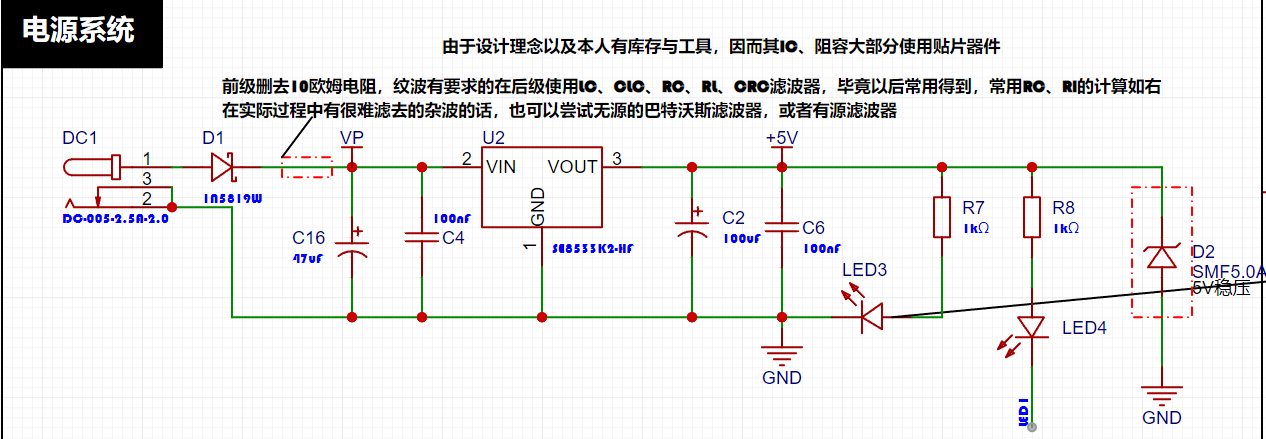
The LDO (Low Dropout Linear Regulator)
project uses a low dropout linear regulator (LDO) as the power supply solution. Voltmeters are typically used in industrial environments where the supply voltage is often 24V or 36V. Therefore, the project selected the SE8550K2 LDO, which has a maximum input voltage of 40V to meet the requirements of these applications. A DC-DC step-down circuit was not used in this project, primarily to avoid ripple interference that might be introduced into the design. Ripple interference can affect the measurement accuracy and stability of the voltmeter. Secondly, omitting a DC-DC step-down circuit also reduces the overall project cost, which is an important consideration in cost-sensitive applications.
However, LDOs generate significant heat under large voltage differentials, so I personally do not recommend using excessively high power supply input voltages. I suggest using the nominal value of 12V for this solution. If you want to use a higher voltage, you can refer to the following circuit:
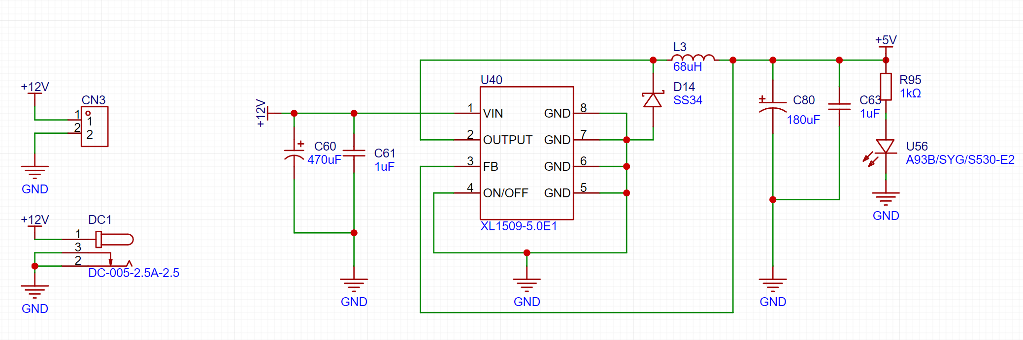
This circuit has been verified by me multiple times and is feasible. Under strict ripple control conditions, I suggest adding a Π-type filter or similar in the subsequent stage.
2. Voltage Sampling Circuit : The
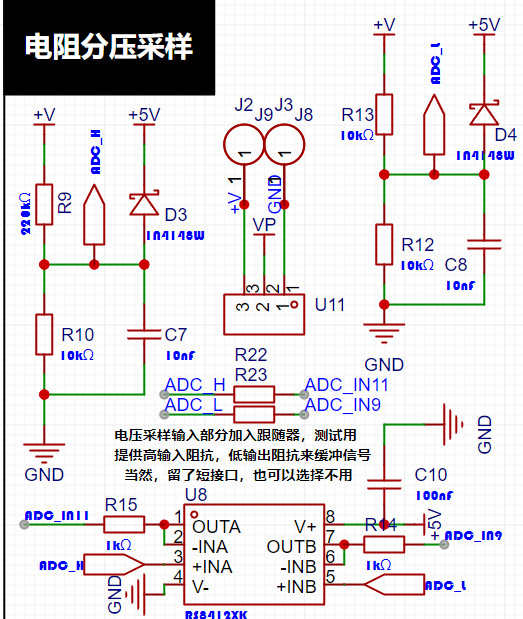
voltage sampling uses the simplest resistor voltage divider sampling, calculated as follows:
The maximum value of the designed voltage to be measured is 30V for safety reasons (the actual maximum display can be 99.9V or 100V).
The ADC reference voltage is 1.5V in this project, and this reference voltage can be configured through the program.
To reduce power consumption in the sampling circuit, the low-side resistor (R10) is typically chosen as 10K based on experience.
The high-side resistance of the voltage divider can then be calculated using the above parameters.
The required voltage division ratio is calculated, i.e., the ADC reference voltage. The input voltage is calculated as 1.5V/30V = 0.05 using known parameters.
The high-side resistance is calculated as low-side resistance/voltage division ratio, which is 10K/0.05 = 200K using known parameters.
A standard resistor is selected: a resistor slightly higher than the calculated value of 200K is chosen. We typically choose E24 series resistors, so in this project, we choose 220K, which is greater than 200K and closest to the calculated value.
Since this project is for experimental verification and does not require very high precision, these resistors do not need to be of high precision. If high precision is required, it is recommended to use high-precision resistors. The Runshi RS8412 dual-channel op-amp is used as a follower; this is not a cost-saving measure, but rather an optimization of the signal.
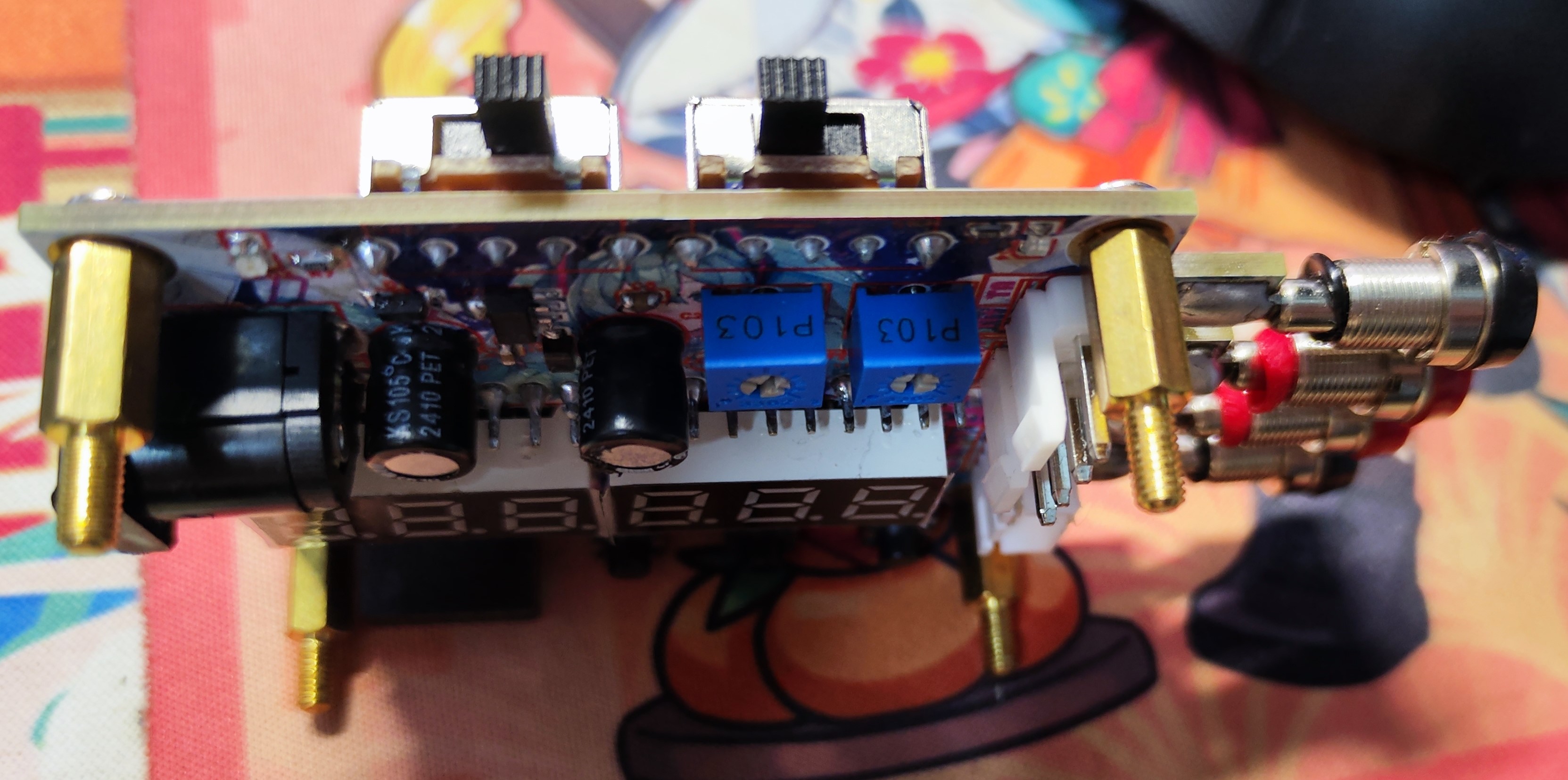
3. Current Sampling Circuit Design and Analysis:

The current sampling resistor parameters mainly need to consider the following aspects:
the maximum value of the pre-designed measurement current. In this project,
the voltage difference caused by the 3A current sensing resistor is generally not recommended to exceed 0.5V.
The power consumption of the current sensing resistor should be selected according to this parameter. Considering the power consumption (temperature) problem under high current, a 1.25W metal chip resistor was selected in this project.
The voltage amplification factor across the current sensing resistor: No operational amplifier was used to build the amplification circuit in this project, so the factor is 1.
Then the current sensing resistance value can be calculated from the above parameters. Selection:
Based on the above data, a 100mΩ current sensing resistor was selected in this project. According to the formula, 3A*100mΩ=300mV, 900mW can be calculated.
If different usage environments are required, especially for scenarios with large currents, the resistor can be replaced with constantan wire or a shunt, or an amplifier can be used to amplify the signal.
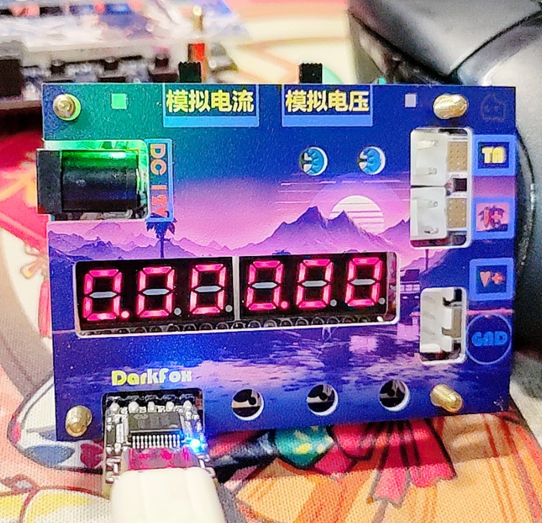
4. Digital Tube Display:
This project uses a digital tube as the display unit.

This project uses two 0.28-inch three-digit common-cathode LED displays as the display device. Compared to a display screen, LED displays offer better visibility in complex environments. The brightness of the LED displays can be increased by using smaller current-limiting resistors to meet the specific needs of the application environment. Furthermore, LED displays have better mechanical properties and are not as easily damaged by external forces as display screens. They are widely used in industrial applications where stability and reliability are crucial. From a development board learning perspective, this makes it easier to learn electronic measurement principles and related development in a targeted manner.
In this project, actual testing showed that a 300Ω current-limiting resistor for the LED displays resulted in good visibility for both red and blue LED displays, with a soft and non-glaring brightness.
5. LED Indicators:
This project added a power indicator and an I/O operation indicator.
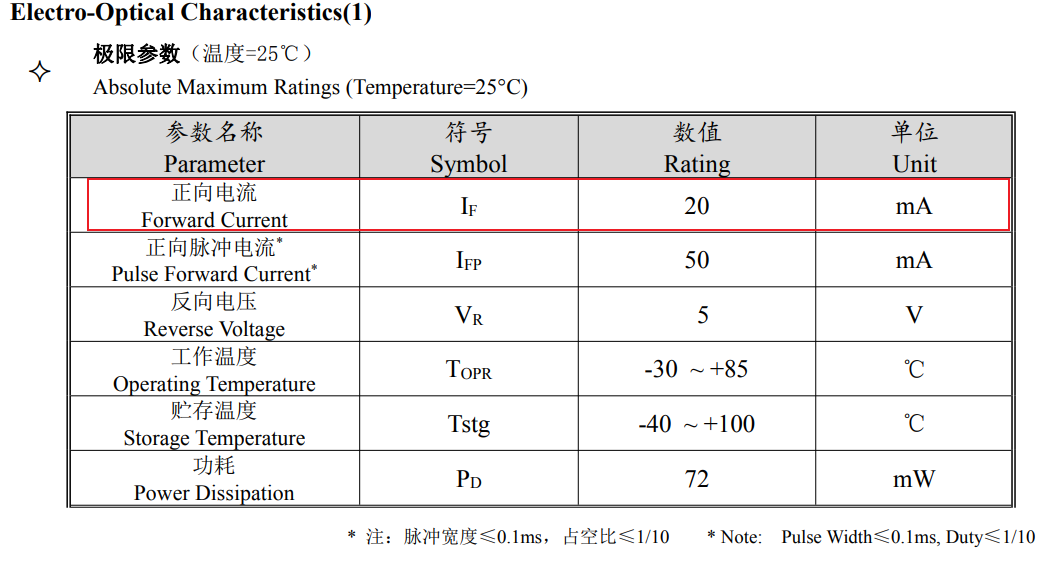
Regarding LED brightness: Maximum LED brightness is very glaring, and maximum brightness output is not recommended.
After determining the required light intensity, adding a current-limiting resistor after calculation can reduce its brightness. Alternatively, PWM control can be used to control its brightness.
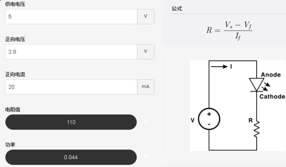
We can perform simple calculations based on the LED light's datasheet. According to the datasheet, we can quickly locate the forward current and forward voltage. Then, based on the current-intensity curve, we can obtain the current limiting value required for the desired brightness, and then deduce the value of the current-limiting resistor. For example, if we want the light to output with a relative intensity of 1:


6. Button circuit design:
Capacitor physical debouncing;
the microcontroller detects high and low levels to determine if the button is pressed;

7. TL431 circuit design for voltage measurement calibration:
This project adds an extra TL431 circuit to provide a 2.5V reference voltage, which can be used to provide an external voltage reference for the chip to calibrate the AD converter;

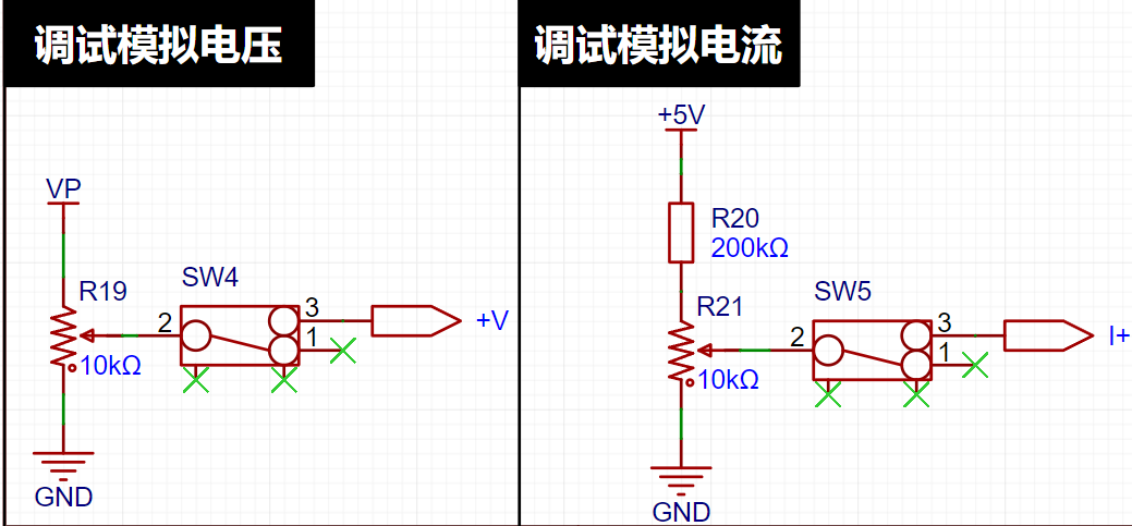
8. Onboard voltage measurement.
To facilitate circuit debugging, a simple resistor voltage divider circuit was added to the sampling end; the reference value can be adjusted by rotating the rheostat; the parameter is controlled by a switch to connect to the circuit;
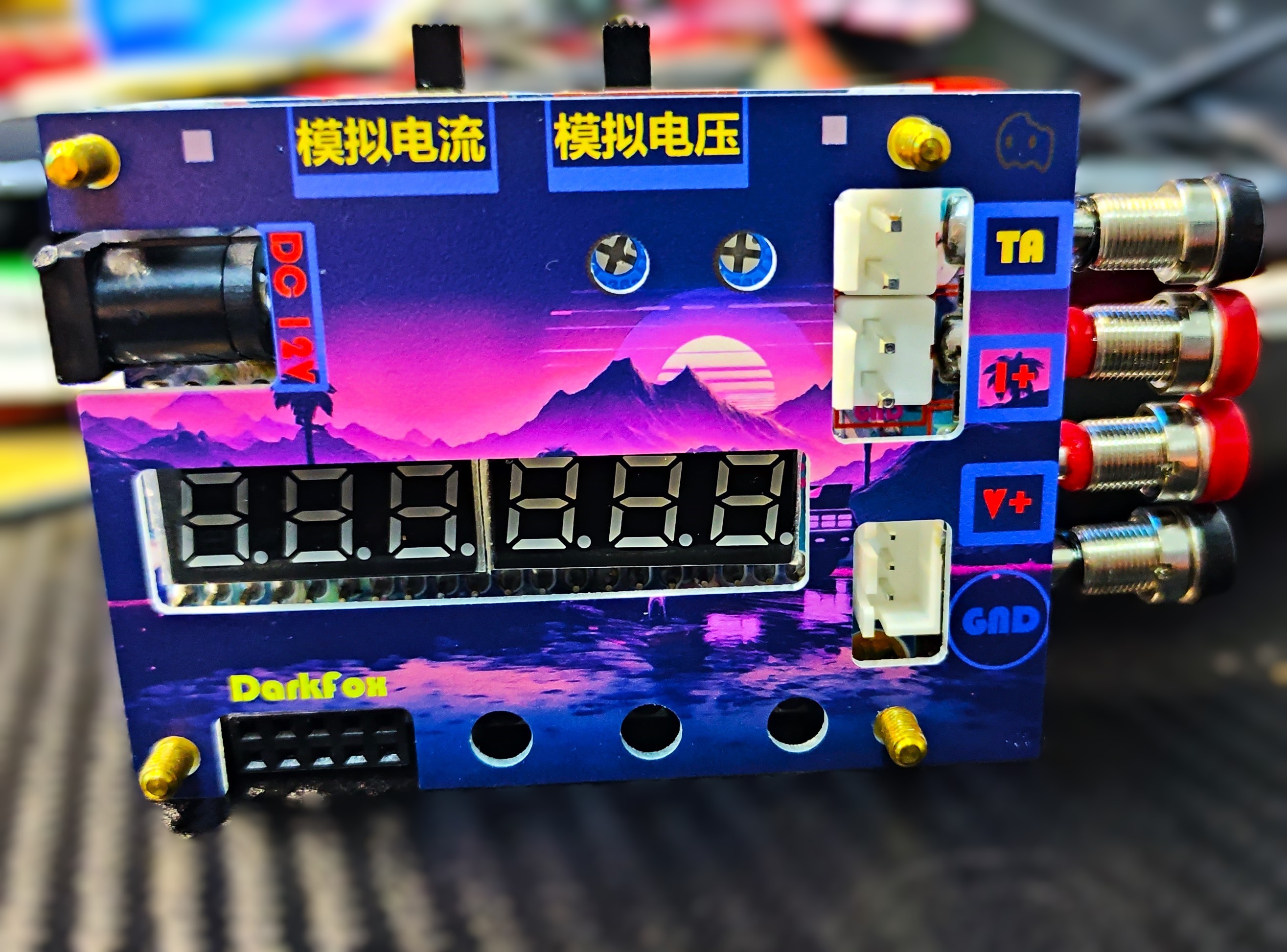
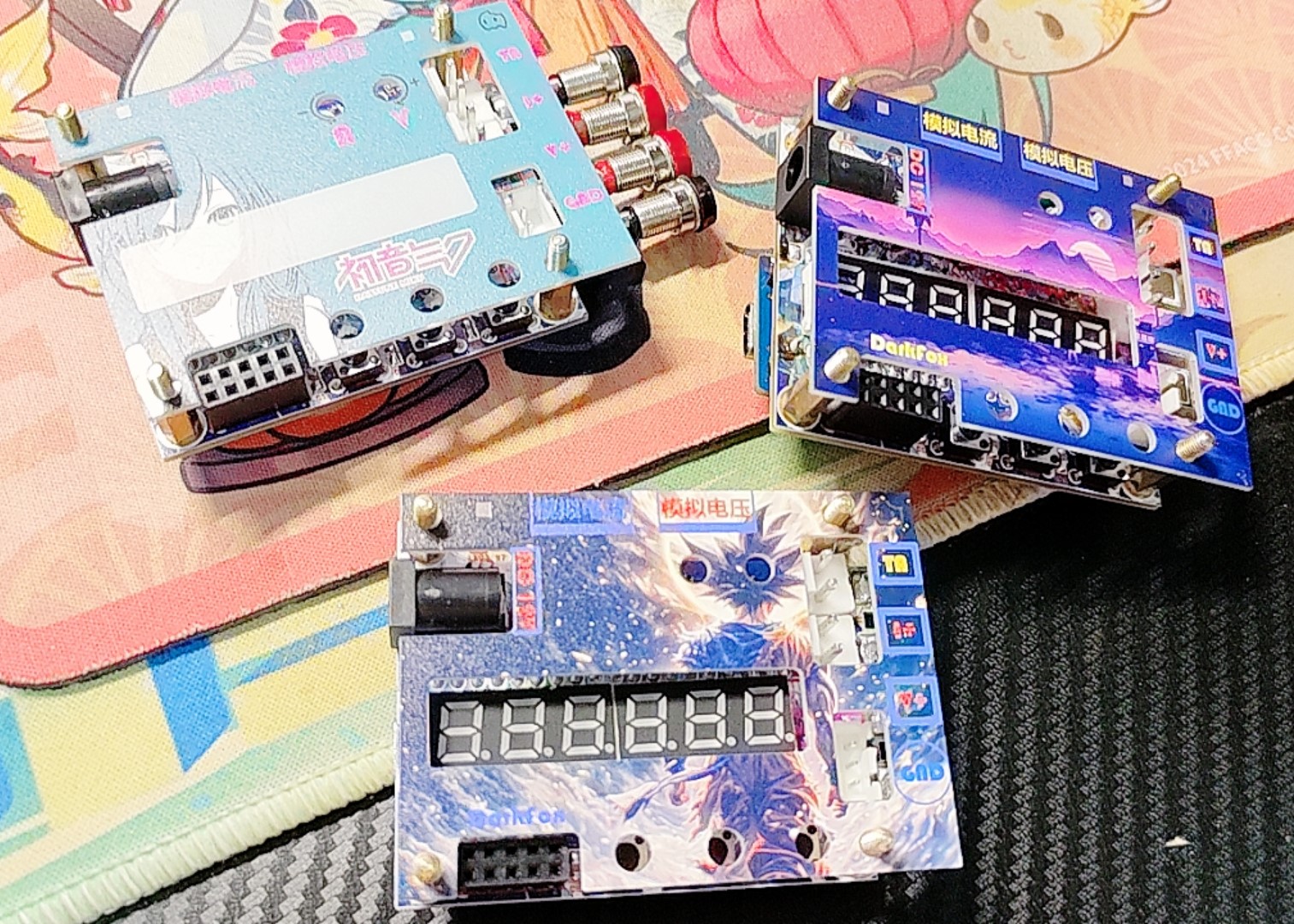
the panel design was designed
because it was my first time using JLCPCB's panel service, so there were some things I didn't understand, and therefore I designed three different panels;
the Miku and
Hatsune Miku versions were designed because I didn't quite understand the impact of the transparency parameter, so at 80.80% transparency, you need to be very close to see the display effect clearly, so it is recommended to use a more transparent or cutout panel for easier observation of the digital tube;

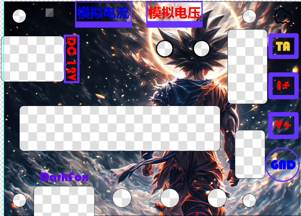
The WuKong version of the
Wukong version has a hollowed-out central display area. Unfortunately, I couldn't find Black Myth materials at the time, so I used Dragon Ball materials instead (not for commercial use). This version was to test the dark effect of LCSC panel printing;
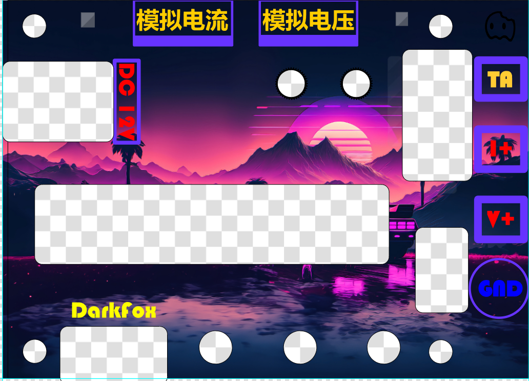
Vaporwave <<<
Vaporwave style theme; the dark tone makes the warm-colored characters have high contrast. If the above two effects are not good, at least there is a usable one; fortunately, LCSC panel quality is very good, and all three can be used.
Precautions:
If you want to replicate my project, you must at least know how to solder 0603 package surface mount components;
when soldering, adhere to the principle of starting from small to large, from surface mount to through-hole, otherwise you will find that some components cannot be assembled, and some components are extremely difficult to solder;
try not to solder the development board directly to the expansion board, it is best to use female headers, otherwise subsequent maintenance and component replacement will become extremely difficult;
analog voltage and analog current switches are only for testing and calibration, and must not be opened during actual use!!!
The horizontal banana head female header requires a slightly higher temperature when soldering, so be careful and do not get burned; safety first!!!
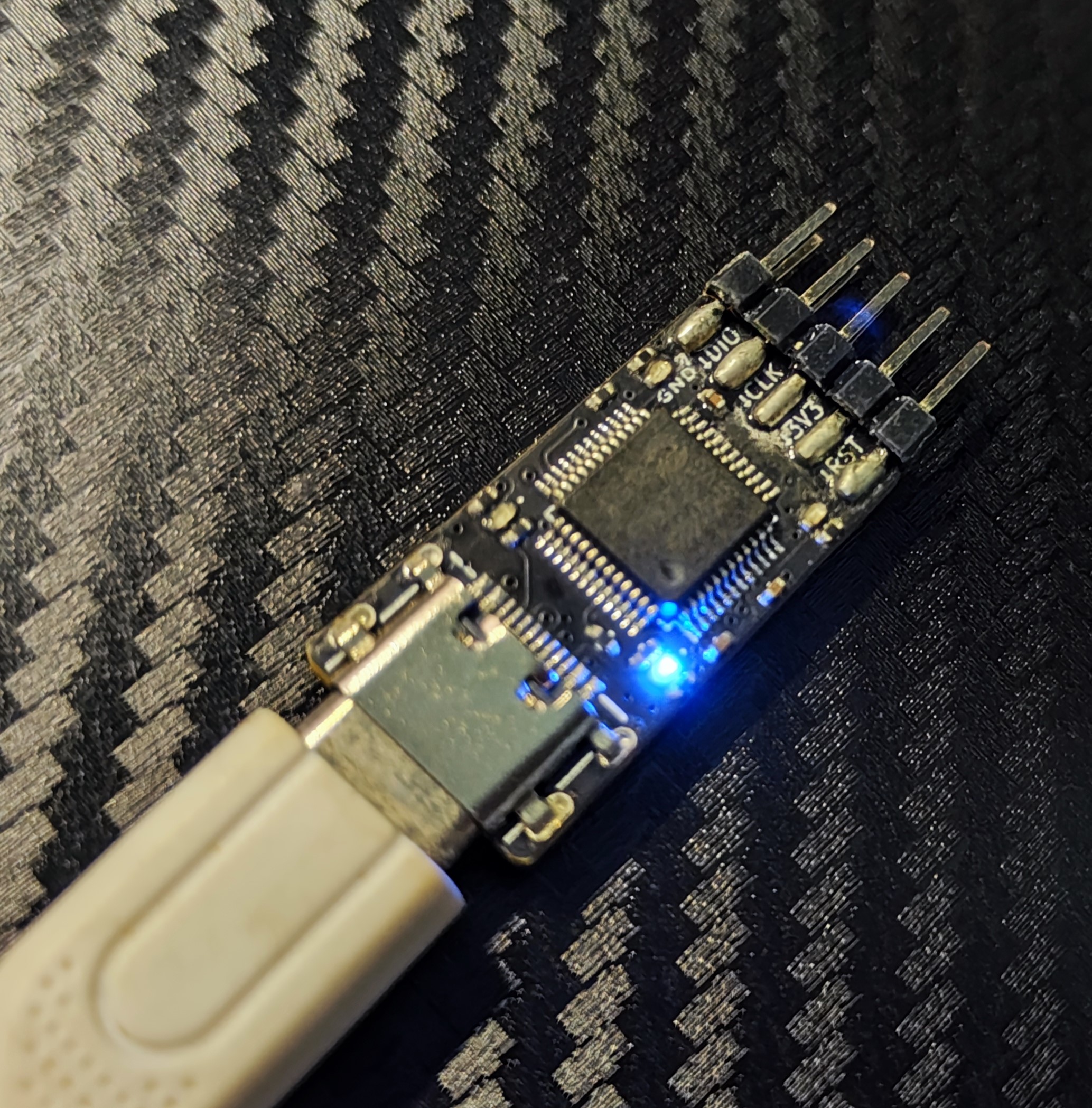
The DAP-link I used is a custom tool, probably the smallest downloader on the market right now, about the size of a USB-A connector. Downloaders compatible with this design are no longer available, so be sure to check your downloader's interface definition! I suggest adapting it to your preferred interface.
The assembly process
was rushed because the materials only arrived around August 10th, and I had to work during the day to support my family, and sometimes work overtime or have social engagements on weekends. I could only spare a little time in the evenings to work on this, so I didn't have time to design the casing. I'll add the casing later when I have more time. However, I did manage to make three different panels. Assembling the panels is simple: just find an M3 stud and connect it to an M3 screw, as shown in the picture.
Then, snap the panel into the hole. I intentionally designed the panel to be about 0.5mm shorter so it can be directly snapped into the screw; if it's not secure, add a nut.
Acknowledgements :
Many thanks to JLCIC Group for organizing this event, and thank you to LCIC for the coupons! The spark of open source will one day ignite a prairie fire!
I am also very grateful to all the engineers for reading. If you are interested, you can try to replicate one. With a PCB roll, the cost of replicating a single one is around ten yuan. Some components can be further simplified. For example, the follower can be omitted, which can save three yuan.
My ability is limited and the design is simple. Please feel free to criticize and correct any shortcomings.


 京公网安备 11010802033920号

 1CIS223-51GGRTV


