Document Version: 1.0.2436
> There's not much to say here.
An NTC is placed in the center of the capacitor bank to monitor its temperature. Silicone thermal paste is used to bond it to the three adjacent supercapacitor cells to improve thermal conductivity and reduce thermal hysteresis for more accurate temperature readings.
The equalization board uses a BW6103 chip for passive equalization protection. Due to its relatively small discharge current, an external WSD2050DN is used for current amplification. Two 2512 500mR alloy resistors are connected in series, resulting in a 1R discharge resistor and a discharge current of approximately 3A.
The current-amplifying MOSFET should have a turn-on voltage of around 1.2V to prevent it from failing to conduct. The discharge resistor should not be too small, otherwise it will divide the voltage with the MOSFET, causing the MOSFET to bear excessive discharge power. A too-small discharge resistor will also lead to excessive discharge current and power, which can easily burn out if heat dissipation is poor. **High-temperature solder paste is recommended for soldering.**
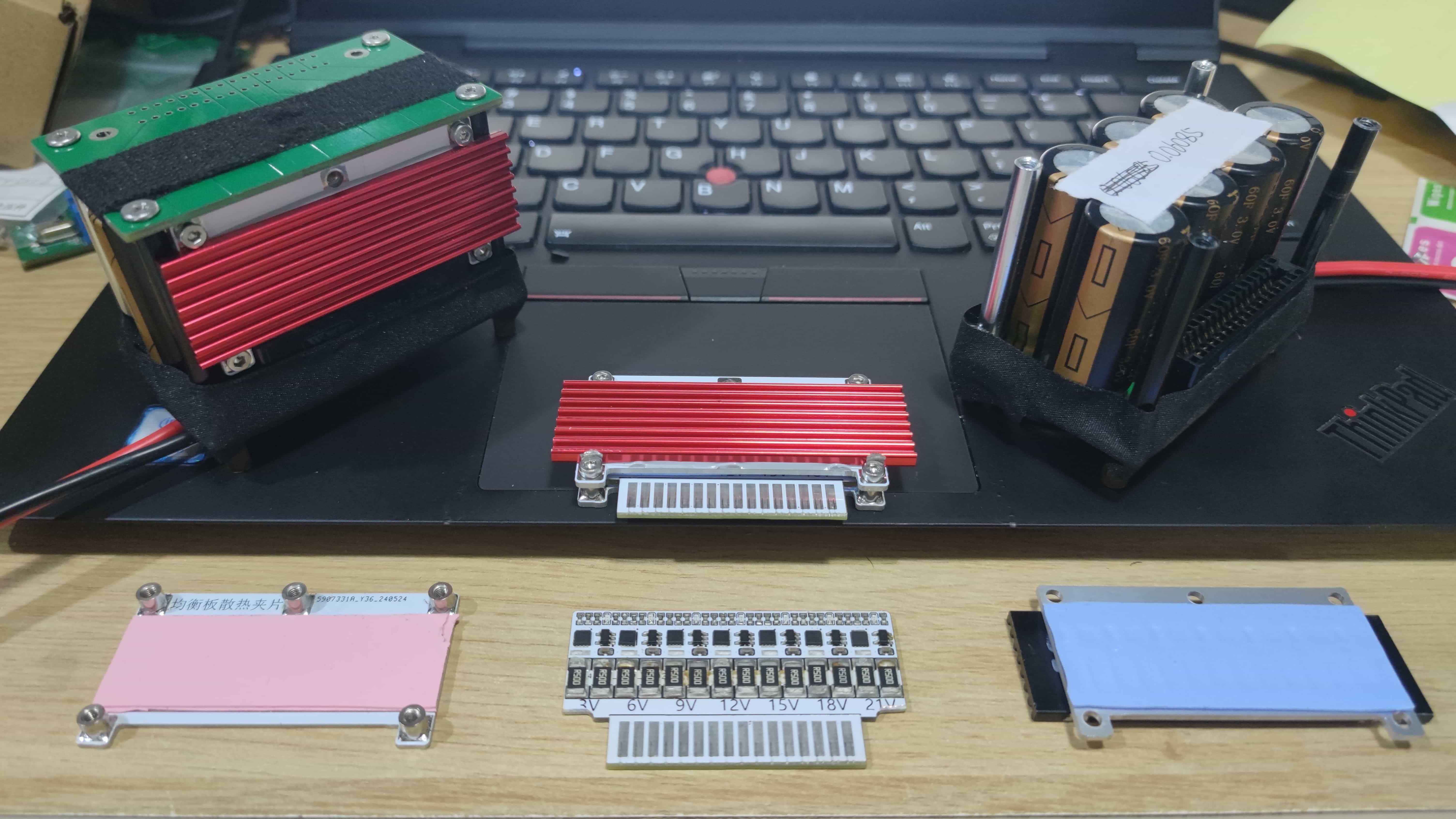
The single-string discharge circuit in this design has a loss of 3W, and the 7-string circuit has a loss of approximately 21W. To prevent burnout, a heatsink is added to the discharge equalization board. Under normal circumstances, the capacitor bank should not be in an overvoltage discharge state.
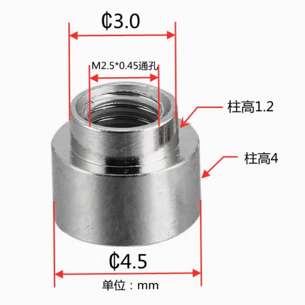
The equalization board heatsink is made using two identical aluminum substrates. One substrate is soldered with five PCB nuts, and the other substrate has a heatsink attached to the opening using silicone thermal paste to increase the heat dissipation area (note that the bolt nuts should be small, otherwise they may jam the heatsink, requiring manual grinding down of the heatsink). Then, 1mm thermal pads are placed on both the front and back of the equalization board (for insulation and heat conduction), and the equalization board is clamped between the aluminum substrates using bolts.
> The heatsink is an M.2 hard drive heatsink, with dimensions of 20*3*70mm; a slightly thicker thickness is acceptable.
> Install the bolts first, then attach the heatsink, as space is somewhat limited; otherwise, a misaligned heatsink may jam the bolts.
Buy smaller bolts and nuts to reduce the chance of them jamming the heatsink.
Use 1mm thermal pads because the overall thickness of the equalization board is approximately 2.5mm, while the PCB nuts are 4mm. The extra 0.5mm allows the aluminum substrate on both sides to apply slight pressure to the thermal pads, resulting in better contact between the thermal pads and the components on the equalization board.
If possible, chamfer the aluminum substrate to make it smoother (or CNC machine it).
If the passive equalization effect is unsatisfactory, an active equalization board can be designed later to replace it.
![SMT Nuts.jpg]
![Equalization Board Interlayer with Text.jpg]

![Family Photo.jpg]


 京公网安备 11010802033920号

 EM7643SU16HZ-45L


