Project Overview:
This project is based on the PCM5102A high-resolution 32-bit 384kHz digital desktop headphone amplifier. The DAC chip used is the PCM5102A, which is doubled in gain by the low-noise op-amp NE5532, and finally output through the TPA6120A unity-gain amplifier. This solution has been verified. Audio data is input through the I2S standard audio interface, and various X-to-I2S interfaces can be freely selected. The output interface is a standard 3.5mm headphone jack. It is a complete TI solution, with no audible background noise in silent mode.
Principle Analysis (Hardware Description) : Power Supply:
The power supply
section uses the WCH CH224K PD protocol power receiving chip. The peripheral circuit is simple and supports multiple voltage input specifications. It is powered by a USB Type-C charger with PD protocol, outputting 12V. Most chargers meet the 12V output capability, but it is recommended to use a high-quality charger to reduce the impact of power supply ripple.
The NCE30P12S performs soft start to prevent excessive current from the subsequent filter capacitor from triggering the charger's overcurrent protection and causing no output.
The DAC is powered by a 3.3V supply, with the PCM5102A distinguishing between digital and analog power. A TPS54302 DC-DC converter draws 5V from the 12V supply, while an AMS1117-3.3 LDO provides the digital 3.3V power to the DAC and also powers devices such as the I2S interface. An ultra-low noise LDO, SPX3819M5-L-3-3, draws the analog 3.3V power to the DAC; the TPS54302 has an internal charge pump to obtain the required positive and negative voltages. An intermediate DC-DC converter is added to avoid directly drawing 3.3V from the LDO's 12V supply, reducing LDO heat and improving efficiency. The
operational amplifier section uses a ±12V dual-terminal power supply solution. A high-power XL6009E1 DC-DC converter is used to build a CUK & SEPIC topology to output ±15V, which is then regulated by L7812 & L7912 LDOs to provide the required ±12V output, offering a high dynamic range.
The power-on popping sound is still resolved using a relay delay.
Additionally, the power supply section is equipped with large-capacity, high-quality electrolytic aluminum capacitors for filtering, improving sound quality; these can be replaced and modified according to individual needs.
The digital signal section
uses a PCM5102A high-resolution 32-bit 384kHz DAC, providing Hi-Fi level high-fidelity audio output. This project provides a standard I2S audio interface input, allowing for free connection to USB, Bluetooth, etc. Specific parameters can be found in the chip datasheet.
The analog signal section
uses a high-bandwidth RC low-pass filter circuit recommended in the datasheet to filter out noise above the sampling frequency of 384kHz, achieving optimal output.
This signal is then divided by a potentiometer, allowing users to adjust the output volume. A dedicated audio-coupled radial non-polar capacitor isolates the DC component of the DAC output before feeding it into a low-noise operational amplifier NE5532 for secondary amplification. The NE5532 is configured as a 2x gain non-inverting amplifier.
The NE5532 output signal is routed through a high-quality headphone amplifier, the TPA6120A, configured as a unity-gain inverting amplifier to improve system stability.
In the PCB layout, digital signals are routed to the back, while analog signals are routed to the front. The analog section is kept away from the DC-DC source, and analog and digital grounds are coupled through a 0R resistor. The analog section is grounded at a single point as much as possible to reduce interference.
Note that
there is no copper plating on either the back or front of the analog signal section to minimize parasitic capacitance. Therefore, keep it away from RF sources, as op-amp feedback is quite sensitive to parasitic capacitance. To balance EMC performance, copper plating on the back can be chosen, but it is best to avoid copper plating on the front, especially in the op-amp feedback section.
The PCM5102A DAC chip generates significant heat; a heat dissipation via pad has been added to the back. It is recommended to add additional heat dissipation fins to the front for further cooling. Other chips generate minimal heat and have no cooling requirements.
It is recommended to use a high-quality PD protocol charger to reduce power ripple.
The filter capacitors can be adjusted according to your needs; it is not necessary to use the same filter capacitors as me.
It is recommended to use a high-quality I2S interface, as phase noise depends entirely on the I2S interface clock.
The PCM5102A theoretically does not require a DC blocking capacitor, so the two radial capacitors can be removed. They can be added for a more Hi-Fi look without any impact.
The cost of a replica is approximately 100 RMB.
Actual product image
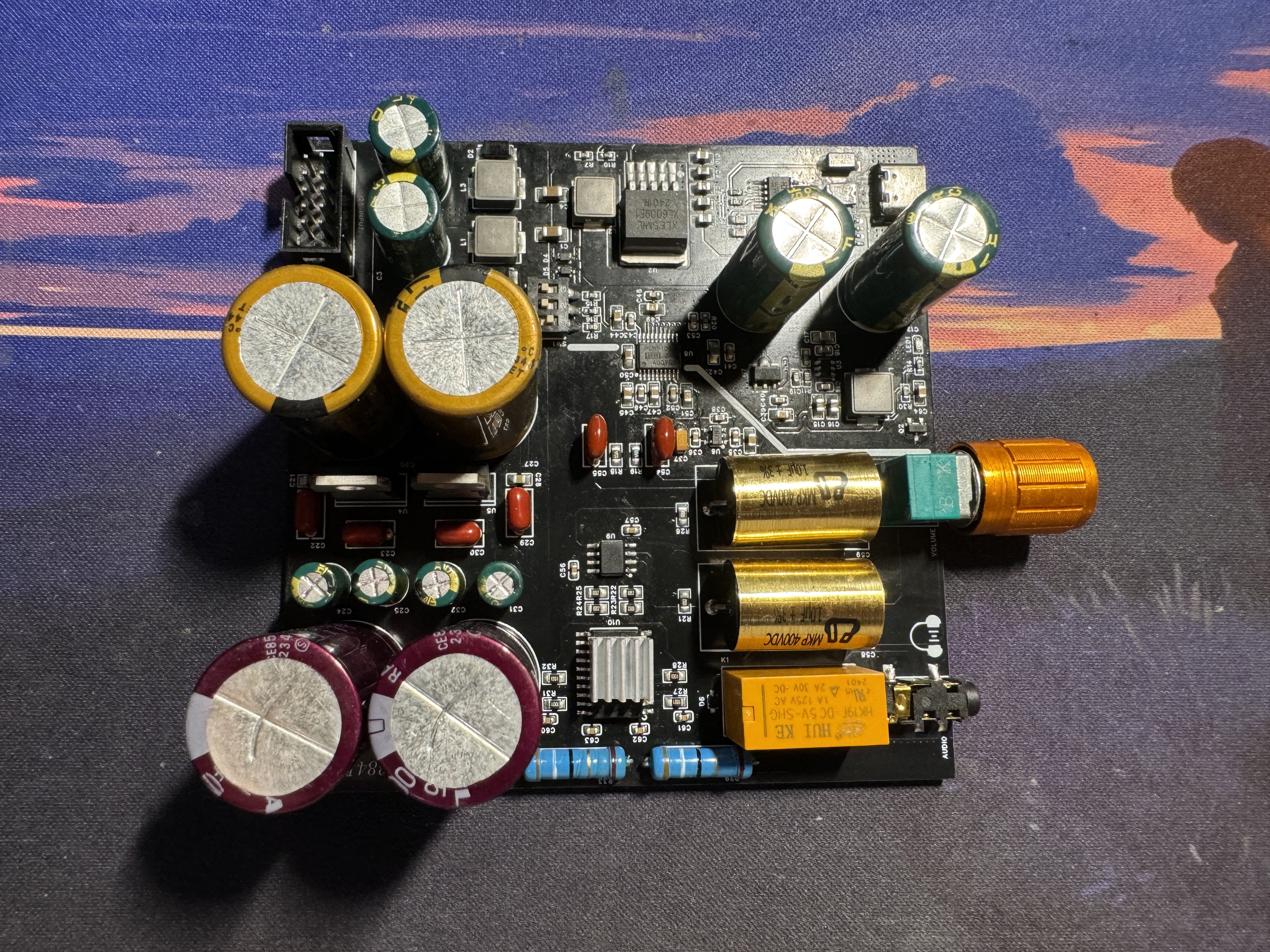

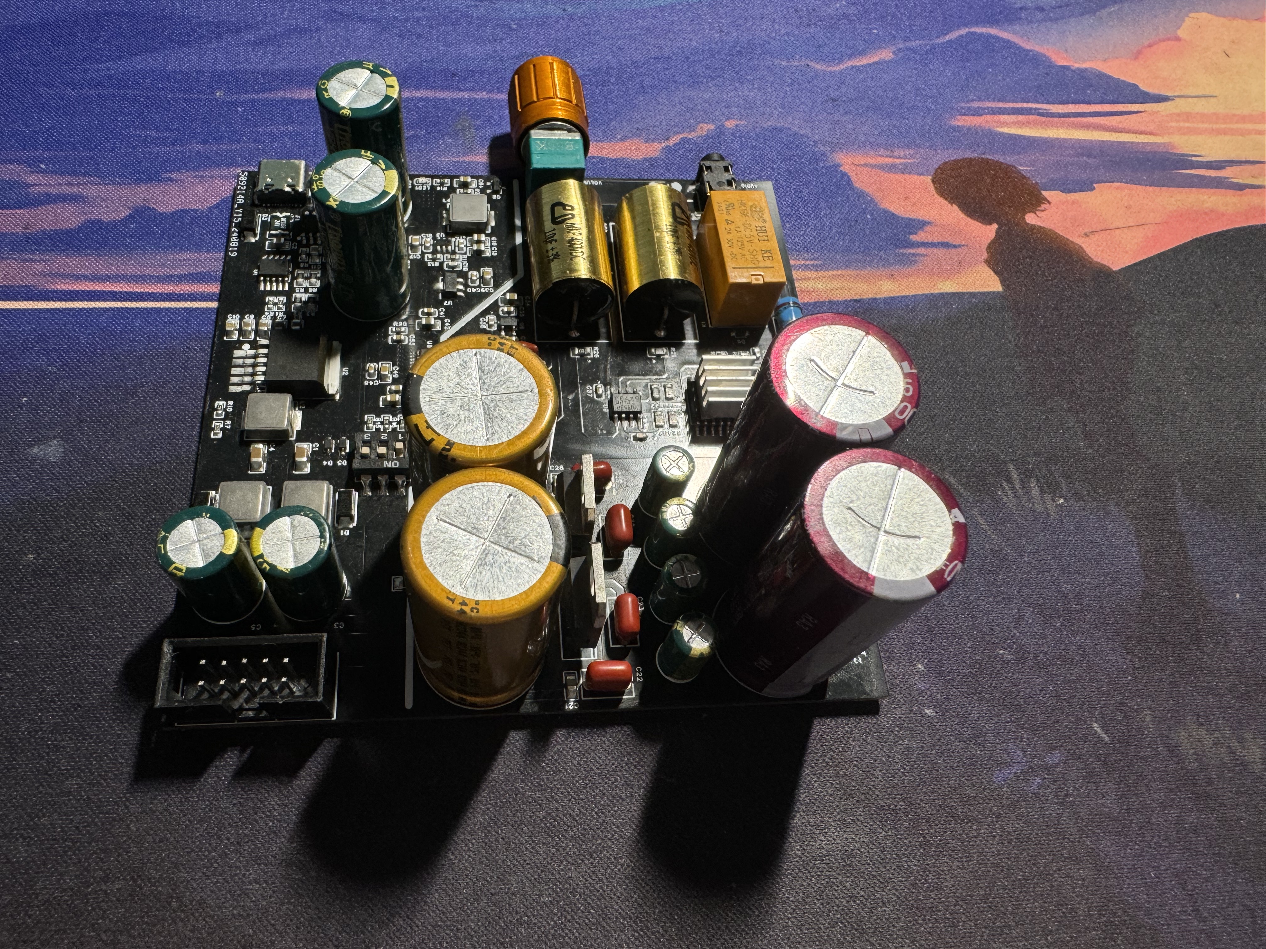
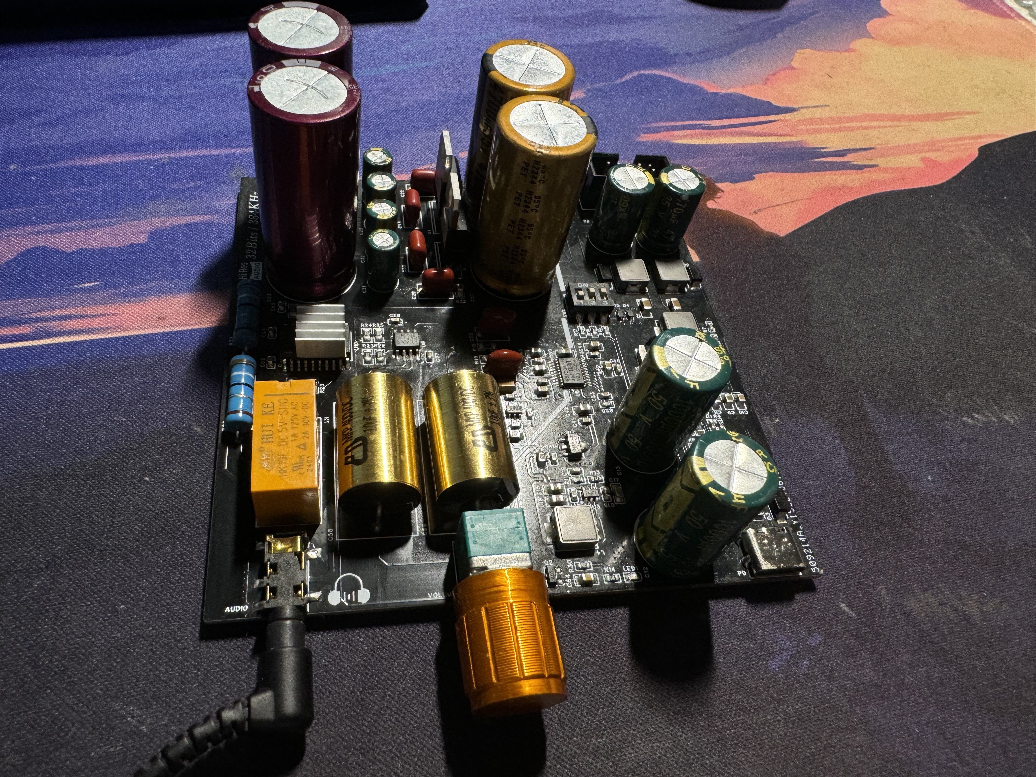
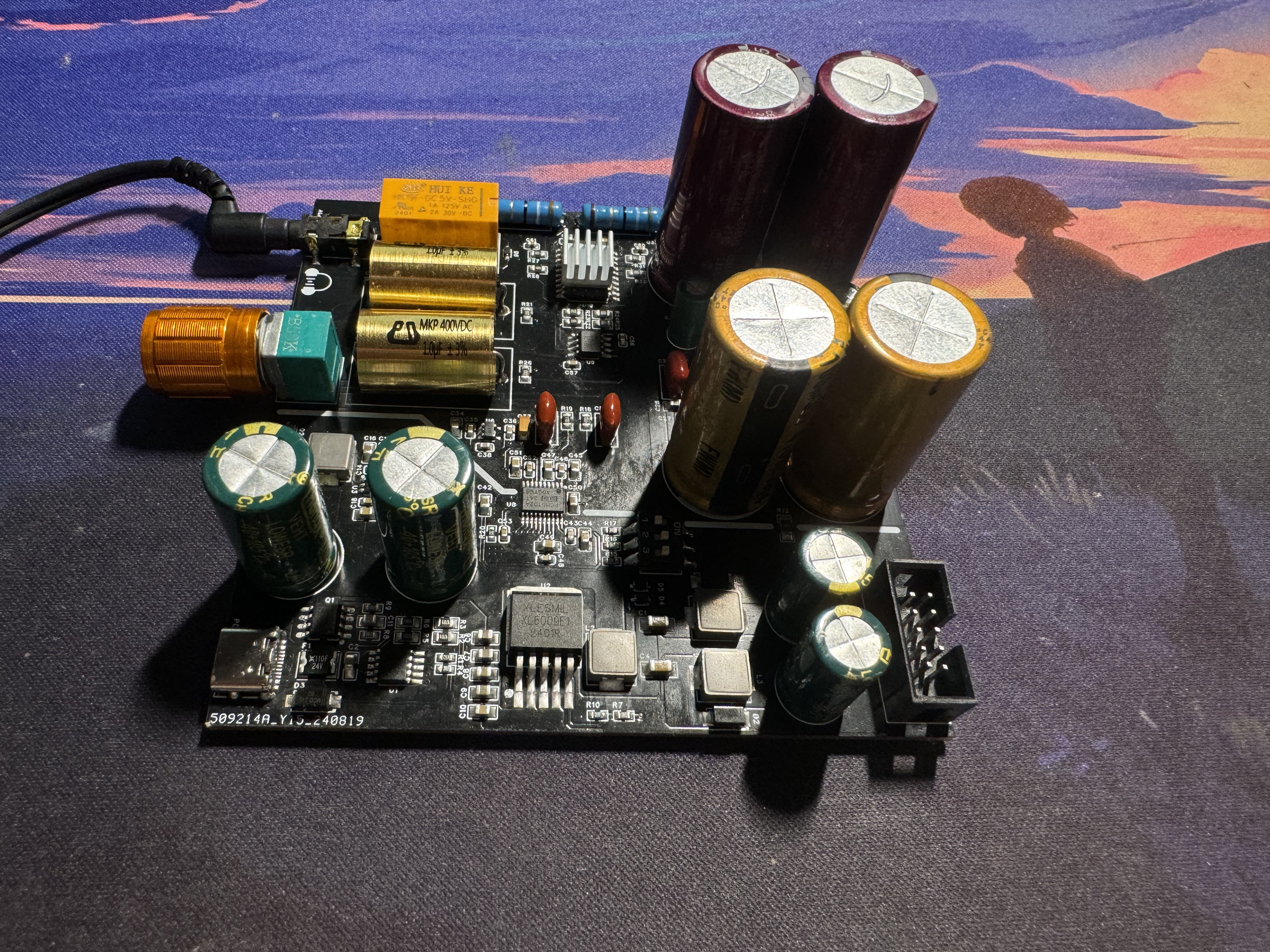
powered on:

PDF_Based on PCM5102A High-Resolution 32-bit 384kHz Digital Desktop Headphone Amplifier.zip
Altium_PCM5102A-based high-resolution 32-bit 384kHz digital desktop headphone amplifier.zip
PADS_PCM5102A-based high-resolution 32-bit 384kHz digital desktop headphone amplifier.zip
BOM_Based on PCM5102A High-Resolution 32-Bit 384kHz Digital Desktop Headphone Amplifier.xlsx
92679
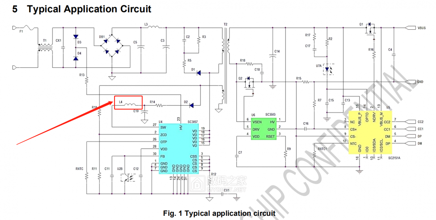
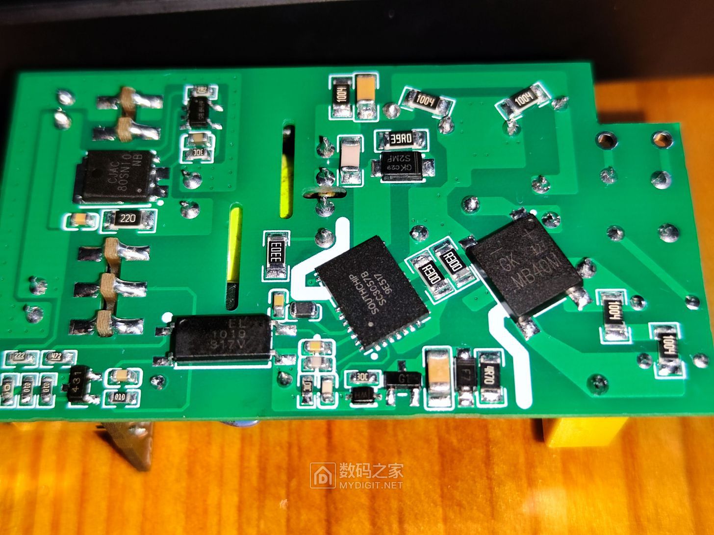
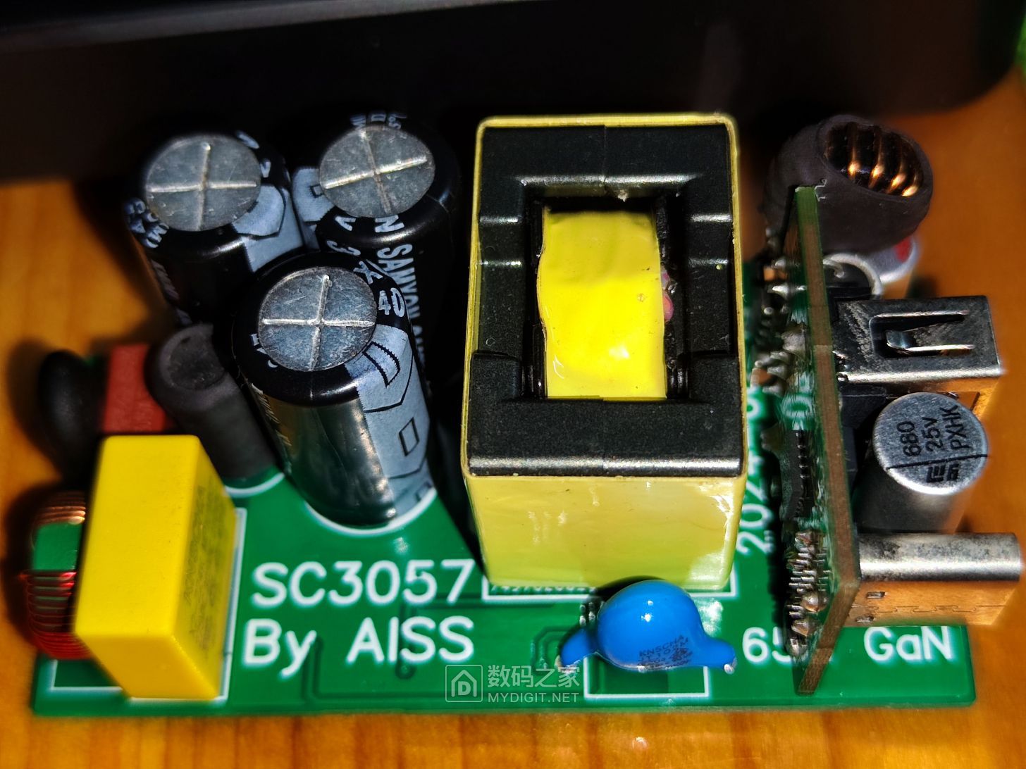
Southchip SC3057 GaN Power Supply
The design utilizes the domestically produced Southchip SC3057B gallium nitride flyback chip, paired with the LP35116P secondary synchronous rectifier chip, enabling a low-cost flyback power supply design.
Warning: Building a switching power supply is inherently dangerous. All parameters in this design have not been verified, and I do not guarantee the correctness of any circuits, parameters, or formulas used in this design. Replicating or referencing this work requires you to assume all possible risks yourself. Please ensure you are a fully capable and responsible individual!!!
Digital Home First Article: Building a GaN Power Supply with a Southchip SC3057 Solution.
Several months later, I'm back to playing with switching power supplies. Although the solution is a common flyback, the Southchip SC3057 chip has too many pitfalls;
it's easy to fall into a trap if you're not careful. Why? Mainly because it adds an internal boost controller
, and this controller is truly absurd. Why put such a mess in a perfectly good flyback power supply? The chip is expensive and difficult to debug.
I've already made three boards and wasted five chips. Each chip costs over five yuan…

I really don't understand the chip design thinking. If you want to increase the chip's VDD range,
why not add more chips? The VDD pin has a withstand voltage, but the boost converter was integrated into
the first board. The inductor issue was overlooked, causing the chip to burn out after power-on.
After checking, I found a missing inductor. This chip is also particularly prone to damaging the optocoupler pins;
the pin layout is unreasonable, with dense pins, which is bad for soldering.
To make it work on such a small board, I removed the RC filter network on the RCS current sensing resistor
and also the RNTC resistor, relying solely on internal temperature protection.
However, the chip's protection is poor; the optocoupler pin and FB feedback pin broke down after only a few tests with an oscilloscope probe.
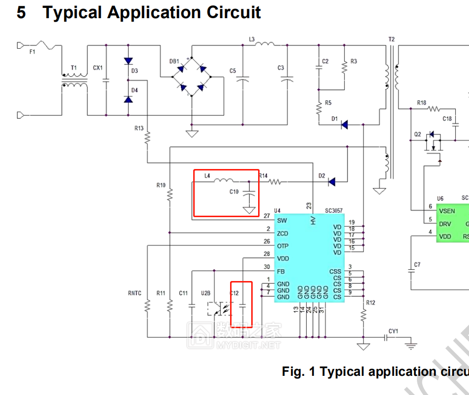
The third pitfall is the startup problem; the VDD startup capacitor must be used according to the recommended value.
I used 2.2uF. It won't start with 25V instead of 50V.
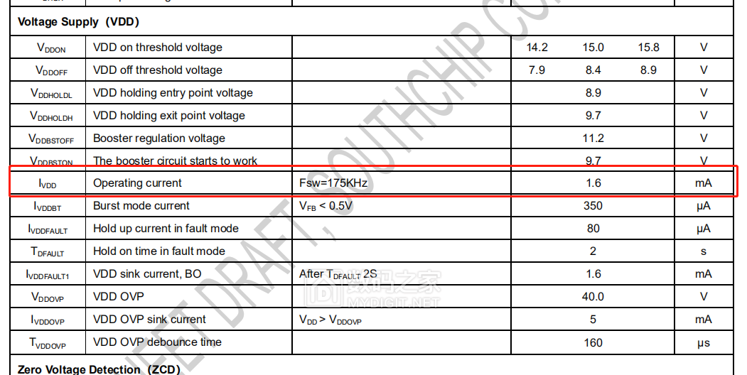
The boost inductor and capacitor on the SW pin are also problematic. The datasheet specifies that the maximum operating current of VDD is 1.6mA,
so only a 0805 inductor package with an inductance of 22uH can be selected.
I suspect the DC derating of the MLCC capacitor is causing a decrease in capacitance, resulting in
insufficient capacitance at high voltages. However, this presents another issue:
its normal startup voltage is 15V. Theoretically, a 25V 2.2uF capacitor should be sufficient,
but in reality, it keeps restarting and cannot work.
Later, I discovered that the power supply from SW is backflowing to the VDD pin. If the voltage on the SW pin is not constant,
it remains in a restart state. It's still the same problem with the filter capacitor
. This startup issue is incredibly troublesome. Moreover, if you directly supply power to the VDD pin, the chip won't work;
it must supply power to the SW pin to start normally. It's really difficult to fix.
This chip has only one advantage: its built-in gallium nitride power transistor has a built-in impedance of only 165mΩ, easily achieving 120W on a bare board at room temperature.
Unlike the Dongke DK065G, the compensation network parameters of the TL431 have been changed.
Directly applying Dongke's compensation network parameters will cause problems with the startup of the SW2303
, resulting in the SW2303 failing to start and operate normally after power-on.
After modifying it to 10nF and 100K, the SW2303 operates stably.

To ensure compatibility with the transformer I previously prototyped, a series voltage regulator circuit was added.
The feedback winding voltage of this transformer can reach 60V.
The supply voltage range of the Southchip SC3057 cannot meet the requirements, and under full load, it may cause the chip to burn out.

——————————————————————————————————————
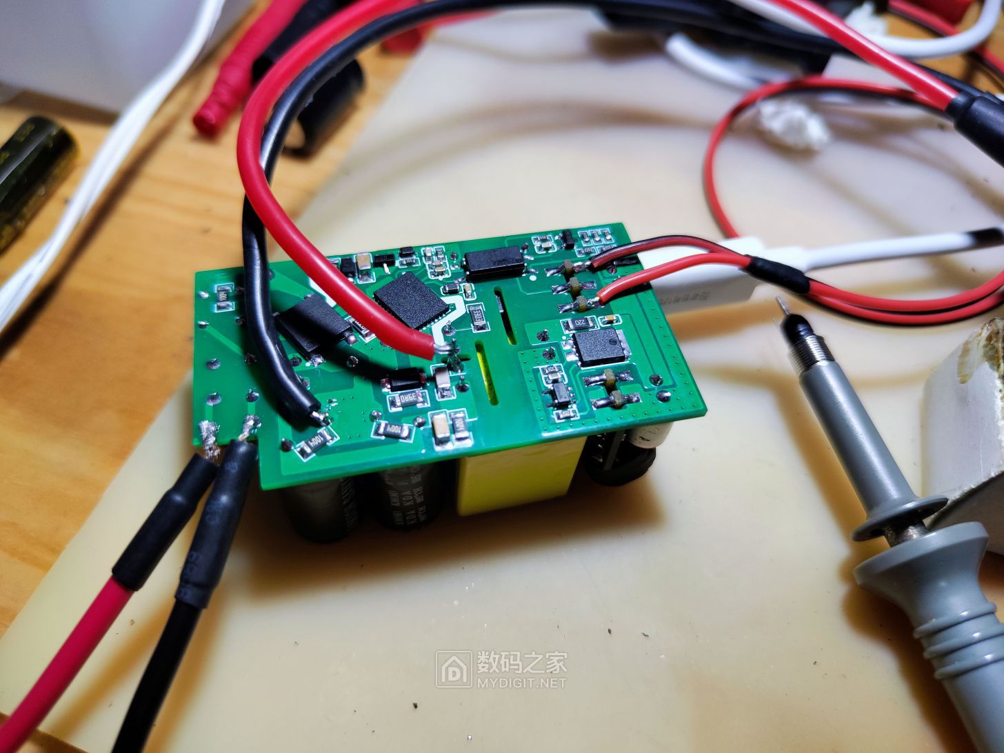
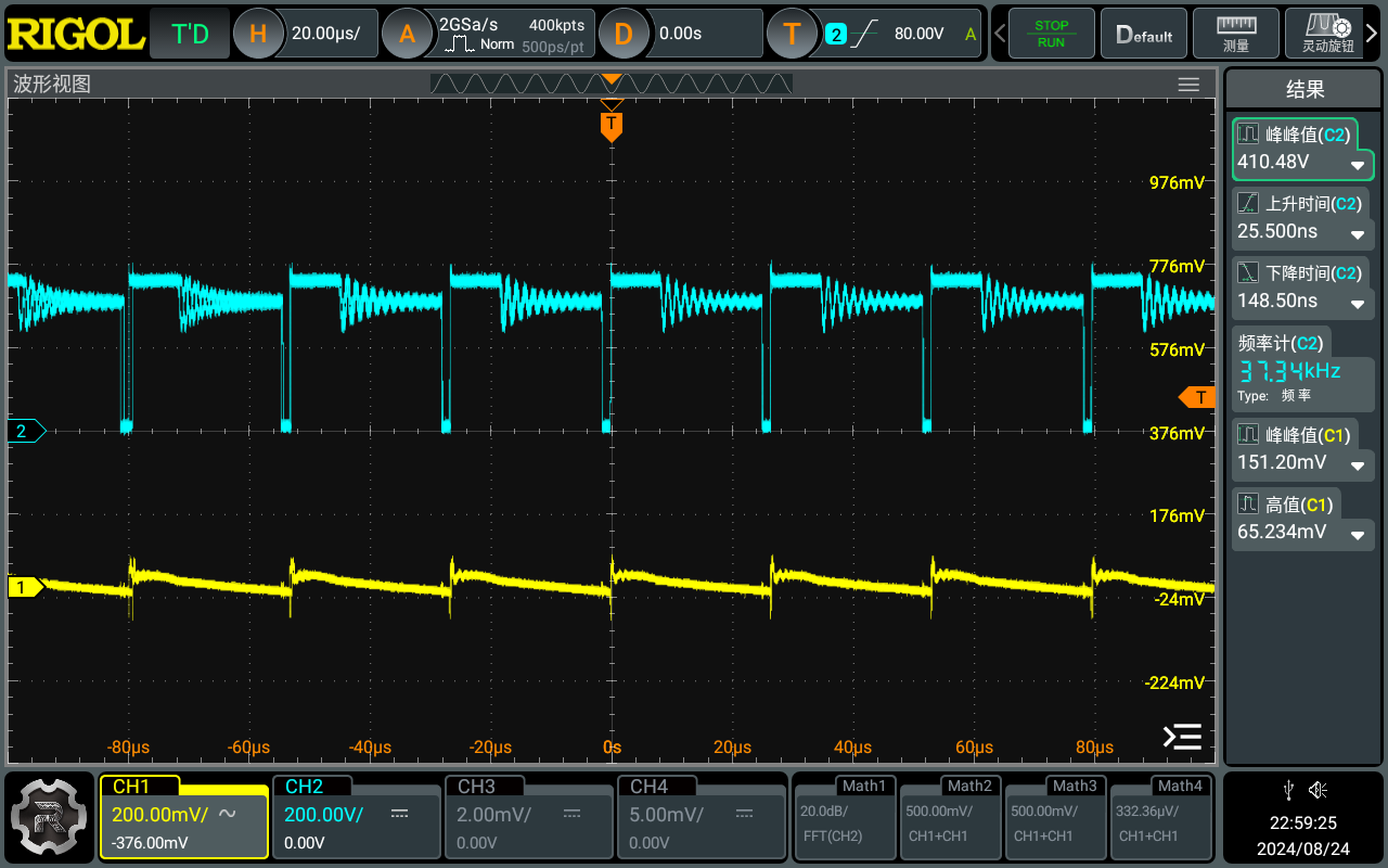
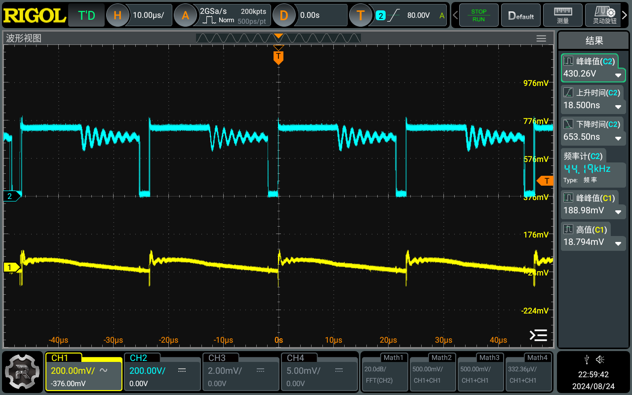
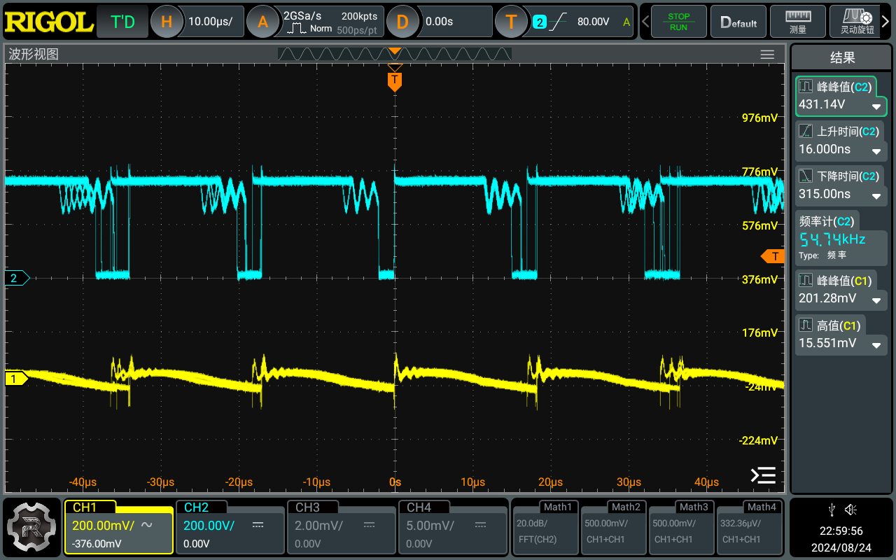
Next are the actual test data. The chip's performance under light load is outrageous, with efficiency exceeding 100%.
5V test, current 1-3A;


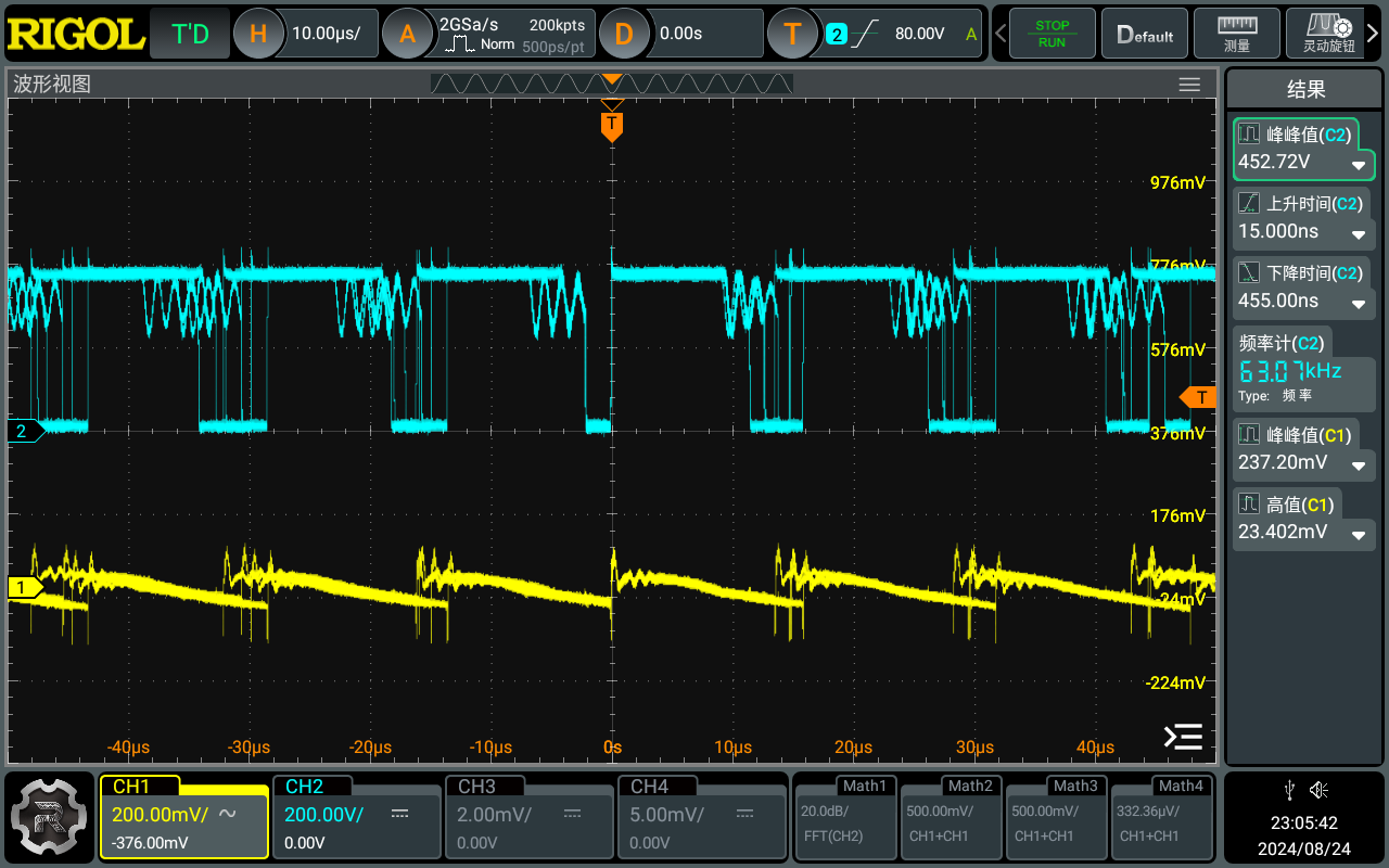
9V test, current 1-3A;
12V test, current 1-3A.


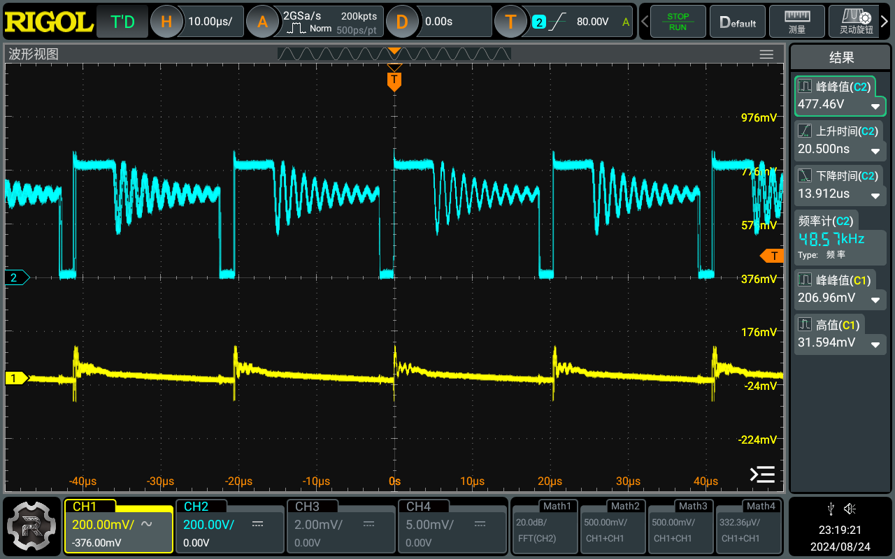
15V test, current 1-3A;


20V test, current 1-3.25A.


Test data summary:

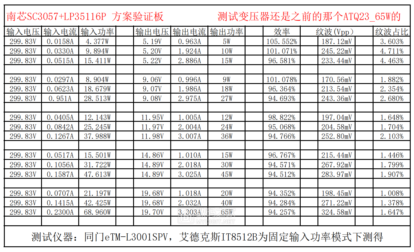
I have doubts about the efficiency of 5V 1A, but the data remained unchanged after restarting the instrument.
Two-hour full-load stress test:

Thanks to the low internal resistance, the chip's stability is not very high.
Gerber_Southchip SC3057 GaN Power Supply_Southchip SC3057 GaN_2024-08-15.zip
SC3057.pdf
Schematic_Southchip SC3057 GaN Power Supply_2024-08-15.pdf
Quasi-resonant power supply design.pdf
BOM_Southchip SC3057 GaN Power Supply.xlsx
92680
#Training Camp#Voltmeter & Ammeter
Voltmeter and Ammeter
I. Description: This is a voltage and current meter using a CW32 microcontroller as the main controller. It employs a voltage follower composed of a current acquisition chip and an operational amplifier to acquire voltage, outputting the data to an on-chip ADC for sampling. It features a digital tube display, an OLED display, and can transmit data to a host computer via Bluetooth. Three control buttons facilitate display and operation, and the voltage sampling range can be controlled via a switch.
II. Hardware Design:
1. Microcontroller: A CW32 microcontroller is used as the main controller, providing sufficient processing power and rich library function support.
2. Current Input: An INA180A2 microcontroller converts the current signal to voltage, and an ADC (Analog-to-Digital Converter) converts the analog signal to a digital signal.
3. Voltage Display: An operational amplifier is used as a voltage follower to acquire the input voltage. ESD control is used to adjust the amplitude of the input to the main chip, and the ADC converts the analog signal to a digital signal
. 4. Data Display: A digital tube and an LCD screen work together. A 128x64 pixel LCD display shows waveform images in real time.
5. Power Supply: USB powered, with an LDO circuit converting the power to 3.3V for each module.
III. Software Design:
1. Signal Acquisition: Write CW32 standard library code, configure analog input pins, sample voltage using an ADC, and derive the actual sampled value using conversion formulas.
2. Data Display: Utilize digital tube library functions and OLED screen library functions to display voltage and current on a digital tube and text and menus on an OLED screen.
3. Button Design: Implement button-based switching of sampling modes and data transmission information.
PDF_#Training Camp#Voltage and Ammeter.zip
Altium_#Training Camp#Voltage and Ammeter.zip
PADS_#Training Camp#Voltage and Current Meters.zip
BOM_#Training Camp#Voltage and Current Meter.xlsx
92681
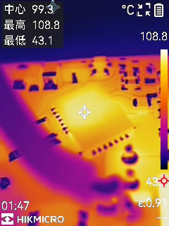
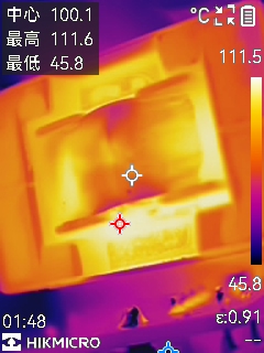
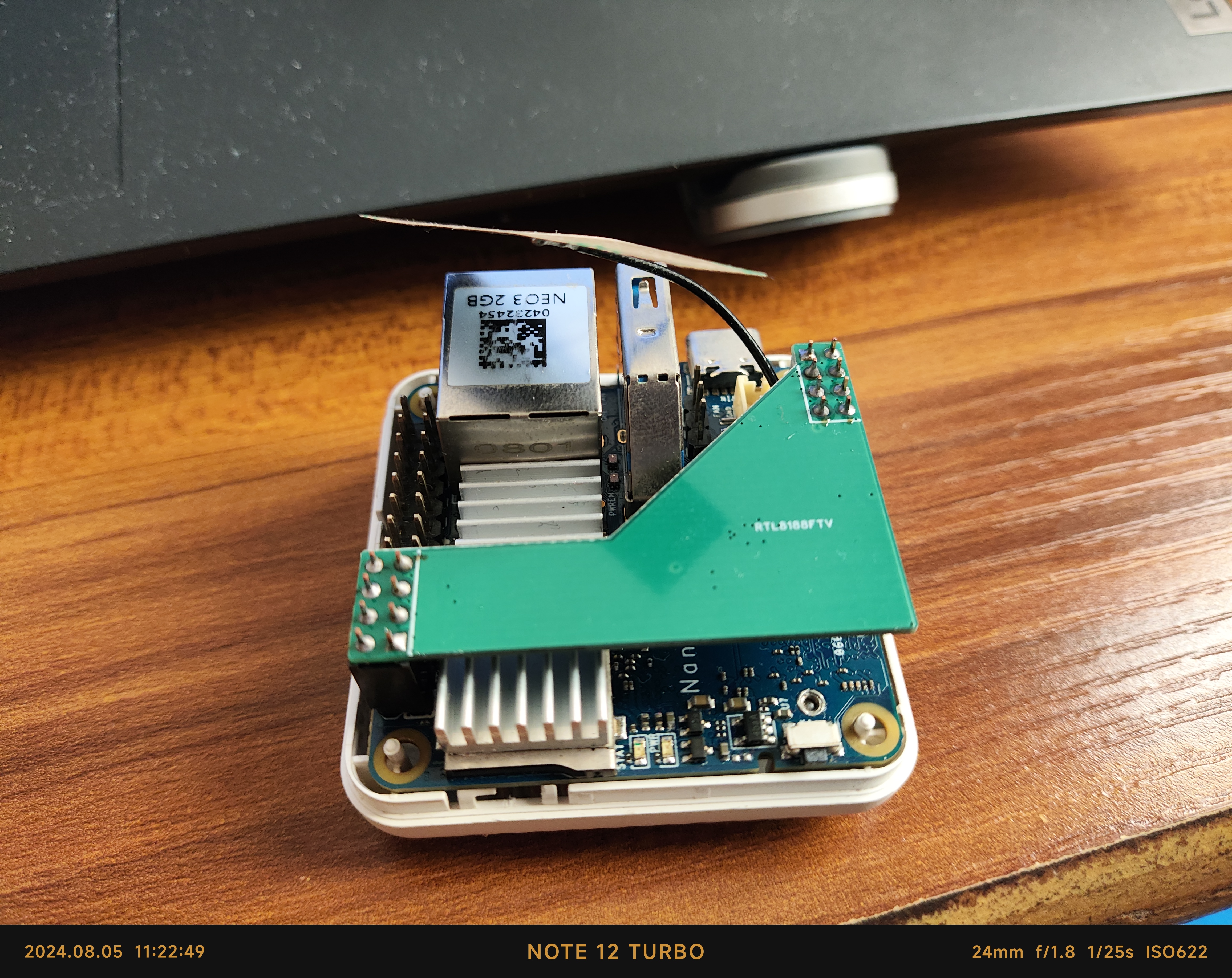
Wireless network card module for NanoPi Neo3
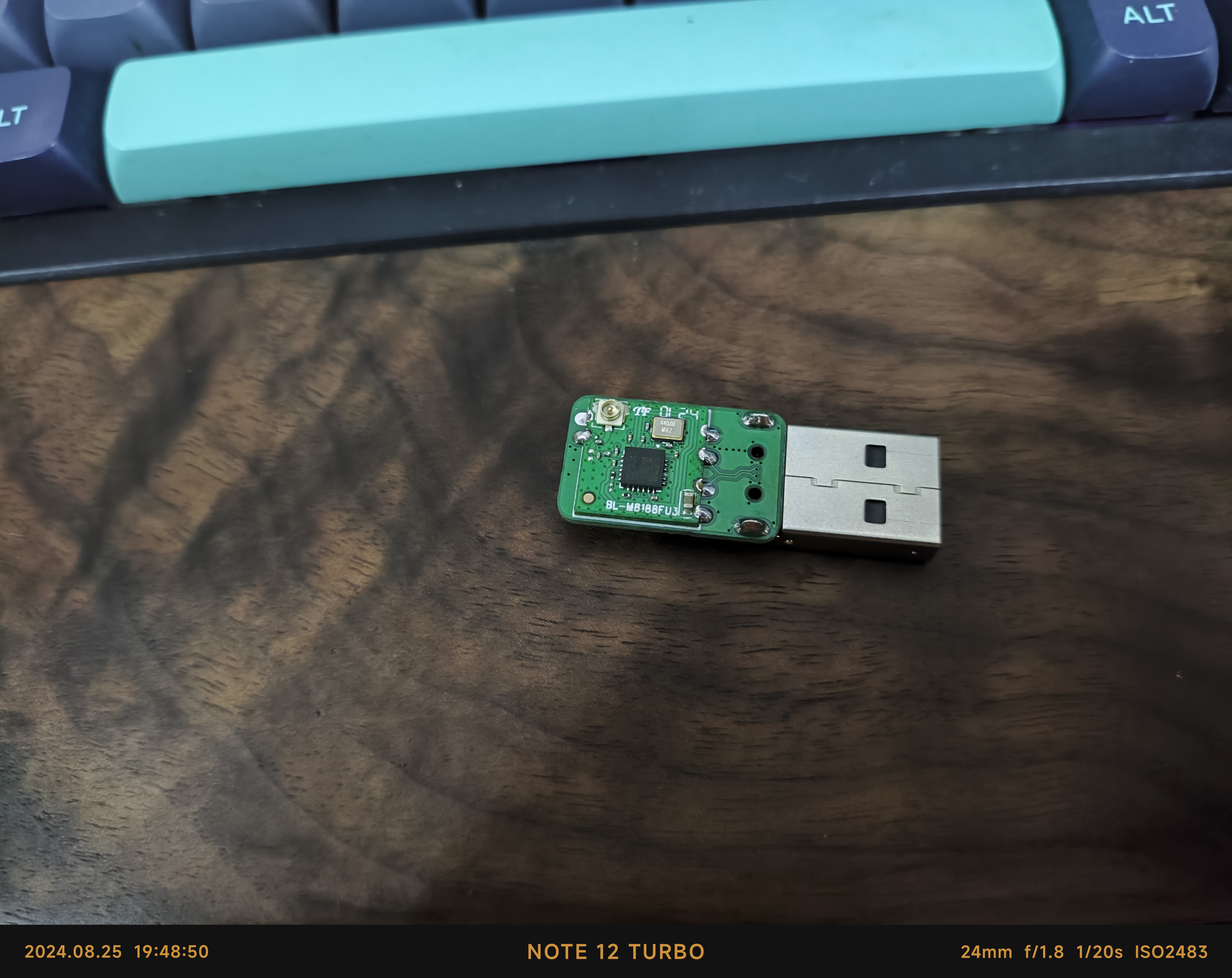
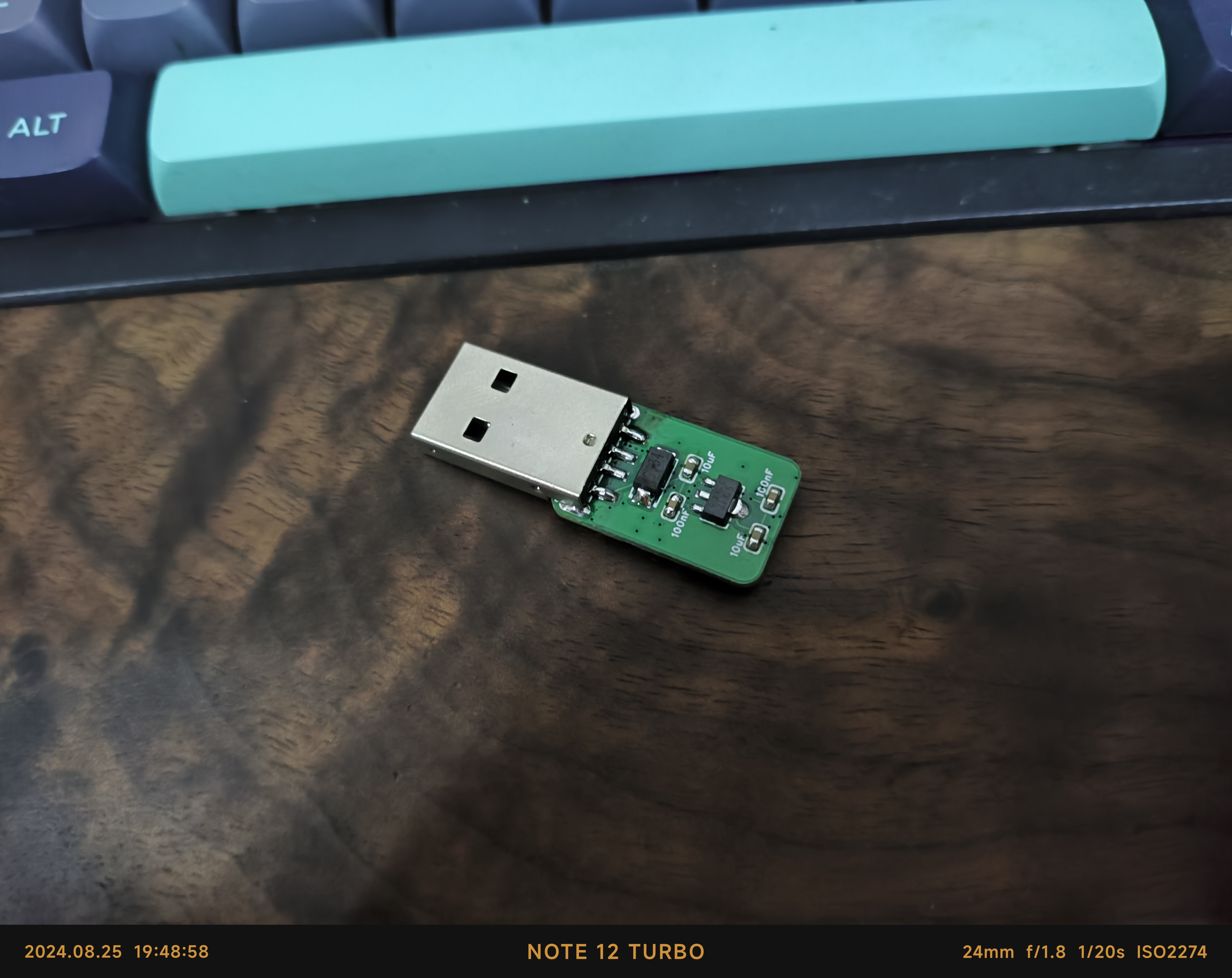
A wireless network card module based on the RTL8188FTV, compatible with NanoPi Neo3, can be directly inserted into the official casing.
This is a wireless network card module for NanoPi Neo3, designed based on the Blink BL-8188FU3 module. It uses a USB interface and is powered by 3.3V. An external antenna can be connected via an IPEX connector.
![IMG_20240805_112334.jpg]

![IMG_20240805_112249.jpg]
![1722827970012.png]

![1722827981125.png]
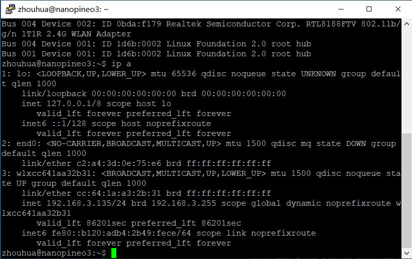
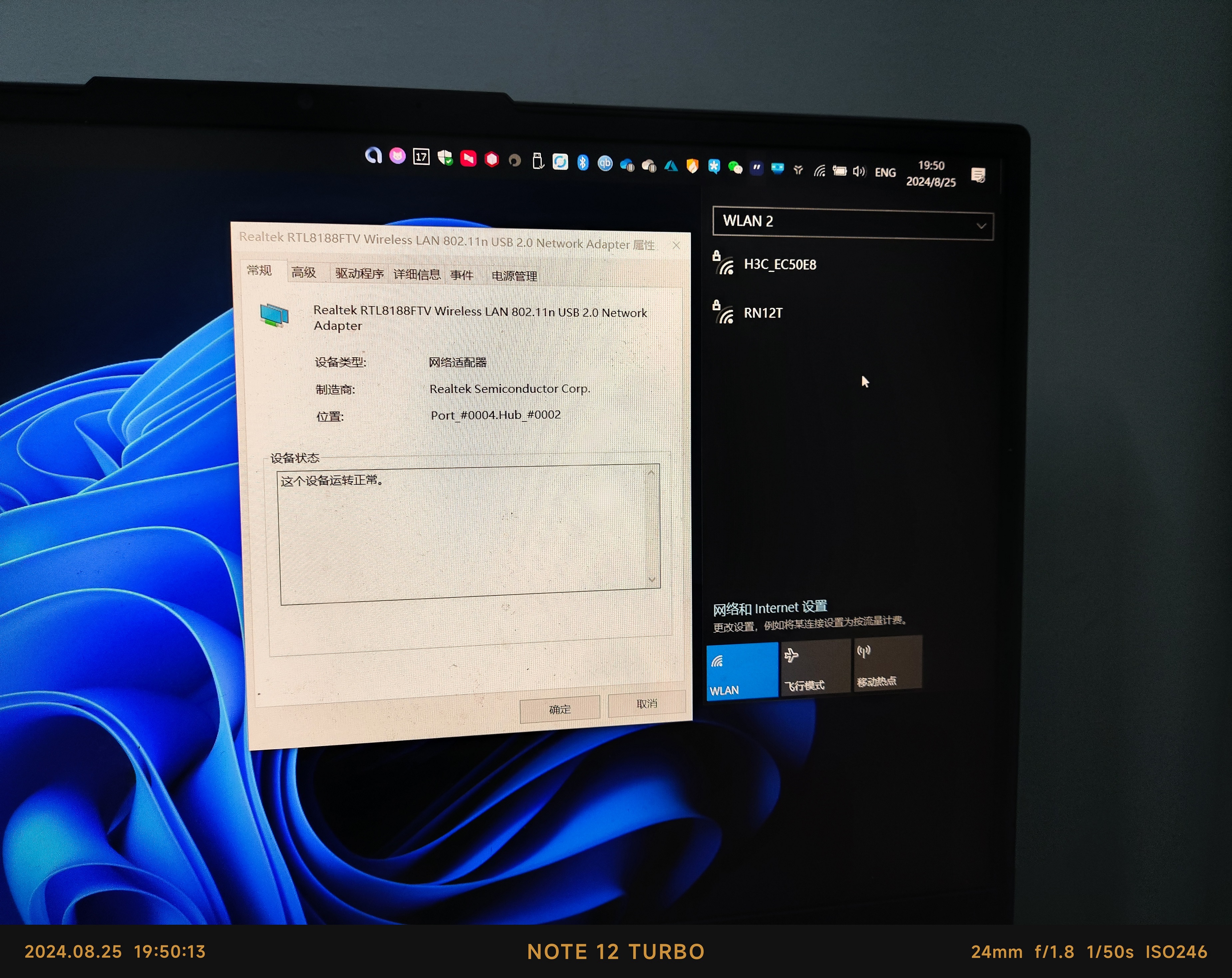
~~Very slow speed and packet loss~~Can be used for SSH.
Regarding the driver:
Use the self-compiled Armbian-unofficial_24.8.0-trunk_Nanopineo3_bookworm_current_6.6.43 image. After initializing the system, clone the [RTL8188FU](https://github.com/i2som/RTL8188FU) project, copy `firmware/rtl8188fufw.bin` from the project directory to the `/lib/firmware/rtlwifi/` directory, and restart the system to use it.
[Mirror Link Download](https://pan.baidu.com/s/1CfjaVG19smlL7qcXEd_qXw?pwd=7ij7)
~~The USB version in the project is unverified!~~
8.25 Update: USB board verified and usable
! ![IMG_20240825_194850.jpg]
![IMG_20240825_194858.jpg]
![IMG_20240825_195013.jpg]
PDF_Wireless Network Adapter Module for NanoPi Neo3.zip
Altium Wireless Network Adapter Module for NanoPi Neo3.zip
PADS Wireless Network Adapter Module for NanoPi Neo3.zip
BOM_Wireless Network Adapter Module for NanoPi Neo3.xlsx
92682
Dong Xiaofeng's voltmeter and ammeter
This project utilizes the LCSC Divinstar development board as its core to achieve high-precision real-time voltage and current measurement. It supports a wide voltage range and USB-C power supply, offering both through-hole and surface-mount versions for flexible selection. All versions feature a 3D housing design, creating an integrated, multi-functional voltage and current meter solution.
Project Overview:
This product is a voltage and current meter designed using the CW32 LCSC Diwenxing development board as its core. It features simultaneous measurement, calibrability, and multiple power supplies.
Project Attributes:
This product is available in through-hole and surface-mount versions. The surface-mount version achieves the same functionality with higher density and features a 3D shell design. It also adds a widely used USB-C interface as a power option to improve usability.
Hardware Part:
Wide Input Module
(
Through-hole and Surface-mount Versions)

Overall Routing: For both through-hole and surface-mount
versions , it is recommended to start with smaller components and solder the through-hole components last. Note that the USB-C connector is relatively difficult to solder; if your soldering skills are average, it is recommended to omit this function. The overall soldering difficulty of the board is relatively low. Software Part: Keil 5 is used for programming and function implementation. Material Selection Plug-in Version Quantity Comment Designator Footprint Value Manufacturer Part Manufacturer Supplier Part 3 100nF C1,C2,C5 CAP-TH_L5.0-W2.5-P5.00-D1.0 100nF CC1H104MC1FD3F6C10MF Dersonic (DERC) C254085 2 10nF C3,C4 CAP-TH_L4.8-W3.2-P5.08-D1.2 10nF CC1H103ZC1ED3F4D1100 Dersonic (DERC) C2761727 1 100pF C6 CAP-TH_L5.0-W2.5-P5.08-D0.7 100pF CC1H101KC74DSL4B10MN Dersonic (DERC) C254079 2 100nF C7,C8 C0805 100nF CC0805KRX7R9BB104 YAGEO (国巨) C49678 1 ZX-XH2.54-3PZZ CH1 CONN-TH_3P-P2.54_2501S-3P ZX-XH2.54-3PZZ Megastar (兆星) C7429633 2 M3960V-02P CN1,CN2 CONN-TH_2P-P3.96_B4P-VH-B-LF-SN M3960V-02P XFCN (兴飞) C492513 3 1N4148 D1,D2,D3 DO-35_BD2.0-L4.2-P8.20-D0.5-RD 1N4148 LGE (鲁光) C402212 1 1N5819 D4 DO-41_BD2.4-L4.7-P8.70-D0.9-RD 1N5819 LGE (Luguang) C402218 1 DC-005-2.5A-2.0 DC CONN-TH_DC-005-2.5A-2.0 DC-005-2.5A-2.0 XKB Connection (China Xingkun) C319099 2 47uF EC1,EC2 CAP-TH_BD6.3-P2.50-D1.0-FD 47uF KS476M050E07RR0VH2FP0 CX (Chengxing) C45100 1 100uF EC3 CAP-TH_BD6.3-P2.50-D1.0-FD 100uF KS107M016E07RR0VH2FP0 CX (Chengxing) C43805 2 22850120ANG1SYA01 H1,H2 HDR-TH_20P-P2.54-VF 22850120ANG1SYA01 JILN (Jinling) C429947 1 PZ254V-11-04P H3 HDR-TH_4P-P2.54-VM PZ254V-11-04P XFCN (Xingfei) C492403 2 B-2100S02P-A110 JP1,JP2 HDR-TH_2P-P2.54-VM-1 B-2100S02P-A110


Ckmtw (灿科盟)
C124375
3
KH-6X6X9H-TJ
K1,K2,K3
SW-TH_4P-L6.0-W6.0-P4.50-LS6.5
KH-6X6X9H-TJ
kinghelm (金航标)
C2837519
2
FJ2381AH
LD1,LD2
LED-SEG-TH_FJ2381AH
FJ2381AH
志浩
C10701
1
MHL5013URDRT
LD_PWR
LED-TH_BD5.8-P2.54-FD
MHL5013URDRT
MEIHUA (美华)
C417347
1
XL-502UWC
LED1
LED-TH_BD5.9-P2.54-RD_WHITE
XL-502UWC
XINGLIGHT (Chengxingguang)
C2895480
1
100mΩ
R0
RES-TH_BD3.5-L9.0-P13.00-D0.5
100mΩ
MF1WS-0Ω1±1%-2T52
VO (Xiangsheng)
C2903206
6
300Ω
R1,R2,R3,R4,R5,R6
RES-TH_BD2.2-L6.5-P10.50-D0.6
300Ω
MFR0W4F3000A50
UNI-ROYAL (Housheng)
C58609
5
10kΩ
R7,R10,R12,R15,R16
RES-TH_BD2.3-L6.5-P10.50-D0.5
10kΩ
MF1/4W-10KΩ±1% T
CCO (Qianzhi Electronics)
C119347
1
220kΩ
R8
RES-TH_BD2.3-L6.5-P10.50-D0.5
220kΩ
MF1/4W-220KΩ±1% T
CCO (Qianzhi Electronics)
C119374
2
1kΩ
R9,R13
RES-TH_BD2.3-L6.5-P10.50-D0.5
1kΩ
MF1/4W-1KΩ±1%T52
Huaxing Electromechanical
C713997
1
10Ω
R14
RES-TH_BD2.2-L6.5-P10.50-D0.6
10Ω
MFR-25FTE52-10R
YAGEO (Yageo)
C138214
1
200kΩ
R17
RES-TH_BD2.3-L6.5-P10.50-D0.5
200kΩ
MF1/4W-200KΩ±1% T
CCO (Qianzhi Electronics)
C119373
2
5.1kΩ
R18,R19
R0805
5.1kΩ
0805W8F5101T5E
UNI-ROYAL (Housheng)
C27834
2
10kΩ
RP1,RP2
RES-ADJ-TH_3296W
10kΩ
3296W-1-103-8mm
BOCHEN (Bochen)
C330432
SMD
Quantity
Comment
Designator
Footprint
Value
Manufacturer Part
Manufacturer
Supplier Part
3
100nF
C1,C2,C5
C1206
100nF
FN31X104K500PXG
PSA (Xinchang Ceramics)
C464972
2
10nF
C3,C4
C1206
10nF
FV31X103K102ECG
PSA (Xinchang Electroceramics)
C394163
1
100pF
C6
C1206
100pF
FV31N101J202ECG
PSA (Xinchang Electroceramics)
C382205
2
47uF
C7,C8
CAP-SMD_BD5.0-L5.3-W5.3-FD
47uF
RVT1E470M0505
HONOR (Honor)
C696191
1
BX-XH2.54-3PZZ
CH1
CONN-TH_3P-P2.50_BX-XH2.54-3PZZ
BX-XH2.54-3PZZ
Bossie (Bossie)
C18077834
2
M3960V-02P
CN1,CN2
CONN-TH_2P-P3.96_B4P-VH-B-LF-SN
M3960V-02P
XFCN (Xingfei)
C492513
3
1N4148
D1,D2,D3
DO-35_BD2.0-L4.2-P8.20-D0.5-RD
1N4148
LGE (Luguang)
C402212
1
1N5819
D4
DO-41_BD2.4-L4.7-P8.70-D0.9-RD
1N5819
LGE (Luguang)
C402218
1
DC-005-2.5A-2.0
DC1
CONN-TH_DC-005-2.5A-2.0
DC-005-2.5A-2.0
XKB Connection (China Xingkun)
C319099
2
47uF
EC1,EC2
CAP-SMD_BD6.3-L6.6-W6.6-LS7.2-FD
47uF
VP1H470M0605
HONOR (Honor)
C4054383
1
100uF
EC3
CAP-SMD_BD6.3-L6.6-W6.6-LS7.2-FD
100uF
RVT1C101M0605
HONOR (Honor)
C37308
2
BX-PM2.54-1-20PY
H1,H2
HDR-TH_20P-P2.54-VF
BX-PM2.54-1-20PY
Bossie (Bossie)
C18078139
1
PZ254V-11-04P
H3
HDR-TH_4P-P2.54-VM
PZ254V-11-04P
XFCN (Xingfei)
C492403
2
B-2100S02P-A110
JP1,JP2
HDR-TH_2P-P2.54-VM-1
B-2100S02P-A110
Ckmtw (灿科盟)
C124375
3
HX TS669TP 250gf 009
K1,K2,K3
KEY-SMD_4P-L6.0-W6.0-P4.50-LS9.0
HX TS669TP 250gf 009
hanxia (韩下)
C5340129
2
FJ2381AH
LD1,LD2
LED-SEG-TH_FJ2381AH
FJ2381AH
志浩
C10701
1
XL-502SURD
LD_PWR1
LED-TH_BD5.9-P2.54-RD_RED
XL-502SURD
XINGLIGHT (成兴光)
C2895492
1
XL-502UWC
LED1
LED-TH_BD5.9-P2.54-RD_WHITE
XL-502UWC
XINGLIGHT (Chengxingguang)
C2895480
1
100mΩ
R0
RES-SMD_L6.4-W3.2
100mΩ
FMF25FPJR100-LH
PSA (Xinchang Electric Ceramics)
C335243
6
300Ω
R1,R2,R3,R4,R5,R6
R1206
300Ω
1206W4F3000T5E
UNI-ROYAL (Thick Sound)
C17887
5
10kΩ
R7,R10,R12,R15,R16
R1206
10kΩ
1206W4F1002T5E
UNI-ROYAL (Thick Sound)
C17902
1
220kΩ
R8
R1206
220kΩ
1206W4F2203T5E
UNI-ROYAL (Thick Sound)
C17956
2
1kΩ
R9,R13
R1206
1kΩ
1206W4F1001T5E
UNI-ROYAL (Thick Sound)
C4410
1
10Ω
R14
R1206
10Ω
1206W4F100JT5E
UNI-ROYAL (Thick Sound)
C17903
1
200kΩ
R17
R1206
200kΩ
1206W4F2003T5E
UNI-ROYAL (Thick Sound)
C17954
2
5.1kΩ
R20,R21
R1206
5.1kΩ
1206W4F5101T5E
UNI-ROYAL (厚声)
C26033
2
10kΩ
RP1,RP2
RES-ADJ-TH_3296W
10kΩ
3296W-1-103-8mm
BOCHEN (博晨)
C330432
4
M3 screws
TP1,TP2,TP3,TP4
M3 screws
1
SE8550K2-HF
U5
SOT-89-3_L4.5-W2.5-P1.50-LS4.2-BR
SE8550K2-HF
SEAWARD (思旺)
C115012
1
TL431(0.5%)
U6
TO-92-3_L4.9-W3.7-P1.27-L
TL431(0.5%)
UMW (友台电子)
C351448
1
HX TYPE-C 6PIN
U7
USB-C-SMD_HX-TYPE-C-6PIN
HX TYPE-C 6PIN
hanxia (韩下)
C18357552
8. Physical verification, voltage measurement.

Simultaneous Voltage and Current Acquisition and Display.zip
WHXY.CW32F030_DFP.1.0.4.pack
PDF_Dong Xiaofeng's Voltage and Current Meters.zip
Altium_Dongxiaofeng's Voltage and Current Meters.zip
PADS_Dong Xiaofeng's Voltage and Current Meters.zip
BOM_Dong Xiaofeng's Voltage and Current Meters.xlsx
92684
electronic


 京公网安备 11010802033920号

 400AA001M1404G


