Key advantages of CW32 in this project
: Wide operating temperature range: -40~105℃;
Wide operating voltage range: 1.65V~5.5V (STM32 only supports 3.3V systems)
; Strong anti-interference: HBM ESD 8KV; All ESD reliability reaches the highest international standard level (STM32 ESD 2KV);
Project focus - Better ADC: 12-bit high-speed ADC, achieving ±1.0LSB INL 11.3ENOB; Multiple Vref reference voltages... (STM32 only supports VDD=Vref);
Stable and reliable eFLASH technology.
Key features of CW32's ADC: This project requires a focus on 4 reference voltage sources. Content from the "CW32x030 User Manual"

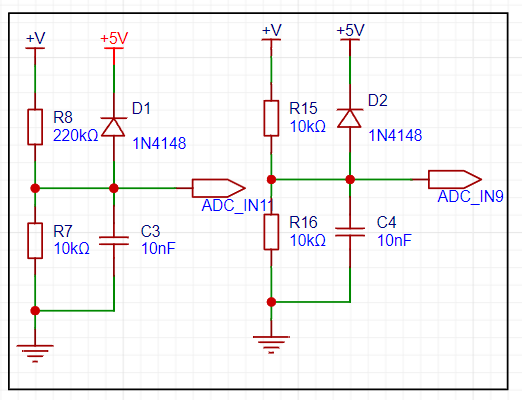
voltage sampling circuit . The voltage
divider resistor in this project is designed as 220K+10K, therefore the voltage division ratio is 22:1 (ADC_IN11).
The voltage divider resistor selection
design measures the maximum value of the measured voltage. For safety reasons, this project uses 30V (the actual maximum display value can be 99.9V or 100V).
The ADC reference voltage is 1.5V in this project, and this reference voltage can be configured through the program.
To reduce the power consumption of the sampling circuit, the low-side resistor (R7) is usually chosen as 10K based on experience.
Then, the high-side resistance of the voltage divider resistor can be calculated using the above parameters.
The required voltage division ratio is calculated, i.e., the ADC reference voltage. The input voltage is designed; using known parameters, 1.5V/30V = 0.05 can be calculated.
The high-side resistance is calculated as the low-side resistance/voltage division ratio; using known parameters, 10K/0.05 = 200K can be calculated.
A standard resistor is selected: a resistor slightly higher than the calculated value of 200K is chosen. We usually choose E24 series resistors; therefore, in this project, 220K, which is greater than 200K and closest to the calculated value, is selected.
If, in actual use, the voltage to be measured is lower than 2/3 of the module's design voltage (66V), the voltage divider resistor can be replaced and the program modified to improve measurement accuracy. The following example illustrates this:
Assuming the measured voltage is no higher than 24V and other parameters remain unchanged,
calculations show 1.5V/24V = 0.0625, 10K/0.0625 = 160K. 160K is a standard E24 resistor and can be directly selected, or a higher value 180K can be chosen with some redundancy.
If, in actual use, the voltage to be measured is higher than the module's 99V design voltage, a different resistor can be selected. To achieve a wider voltage measurement range, one can choose to replace the voltage divider resistor or modify the reference voltage. The following example illustrates this:
Assuming the measured voltage is 160V, the solution is to increase the voltage reference to expand the range.
Given that the voltage division ratio of the selected resistor is 0.0145, we can calculate 160V * 0.0145 = 2.32V using the formula. Therefore, we can choose a 2.5V voltage reference to expand the range (increasing the range will reduce accuracy).
Considering the potential fluctuations in the measured power supply, a 10nF filter capacitor is connected in parallel with the low-side voltage divider resistor to improve measurement stability.
Range switching:
In this project, an additional voltage sampling circuit was added. Therefore, we can discuss the significance of range switching for improving measurement accuracy. Multimeters often have multiple range settings for more accurate measurements. By adjusting different ranges, the optimal measurement accuracy of the measured point within the corresponding range can be obtained.
This project requires a combination of hardware and software to achieve this function. When we first use the ADC_IN11 channel mentioned earlier to measure voltages below 30V... If the measured voltage is within 0~3V, the ADC_IN9 channel is used for measurement. In this case, the measurement accuracy is greatly improved due to the reduced voltage division ratio. There are many ways to implement gear shifting, and the development board design provides more design possibilities.
Voltage and
current calibration using a digital tube display:
This project uses a digital tube as the display unit.
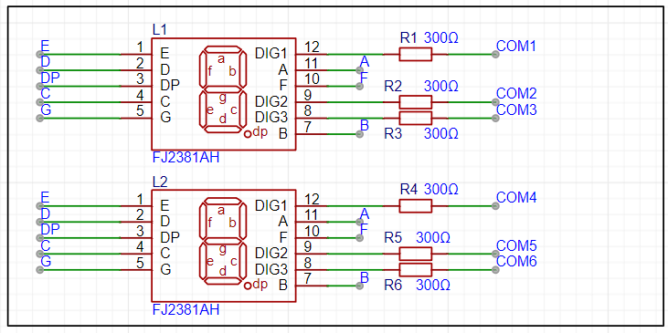
Digital tube driving principle
: Basic structure of a digital tube:
A digital tube is usually composed of seven or eight LED segments (eight segments in this project). Each segment represents a part of the digital tube and can display numbers 0-9, letters AF, etc.
Digital tubes have two types: common cathode and common anode. The difference lies in whether the common terminal COM of the LEDs (i.e., the end connecting all LEDs) is connected to the negative or positive terminal of the power supply.
Driving method:
Segment selection: The desired number or character is displayed by controlling the on/off state of each segment of the digital tube. Each segment corresponds to a control signal; when the control signal is on, the segment will light up, and vice versa. (a, b, c, d, e, f, g, dp)
Bit Selection: The desired digital tube is selected by controlling its bit lines. Bit line control sets the bit line of the desired digital tube to a high level and the bit lines of other digital tubes to a low level. By continuously switching the state of the bit lines, display switching between multiple digital tubes can be achieved.
Driving Circuit:
The digital tube driving circuit can be implemented using hardware circuits, such as integrated circuits like digital signal processors (DSPs), microcontrollers (MCUs), or shift registers to generate control signals suitable for the LEDs.
These control signals can be in the form of pulse width modulation (PWM) signals, serial data signals, etc. By controlling the frequency, width, and amplitude of these signals, the brightness of the digital tube can be controlled, thereby displaying the desired numbers or letters.
Software Control:
In addition to hardware driving circuits, digital tubes can also be driven by software. By programming to generate control signals suitable for the digital tubes, more flexible and complex display effects can be achieved, such as scrolling numbers or alternating numbers.
Driving Common Cathode and Common Anode Digital Tubes:
For common cathode digital tubes, the common cathode pin is connected to the negative terminal of the power supply, and the control pin is connected to the output pin of the control chip. When a number needs to be displayed, the control chip outputs a corresponding encoded signal to the control pin, causing the corresponding LED segment to light up.
For common-anode seven-segment displays, the working principle is similar to that of common-cathode seven-segment displays, except that the common-anode pin is connected to the positive terminal of the power supply, and the control pin is connected to the output pin of the control chip.
Encoding Display:
To display the corresponding number or character on the seven-segment display, the segment data port must output the corresponding character encoding. For example, to display the number "0", the character encoding for a common-anode seven-segment display is 11000000B (i.e., C0H), while the character encoding for a common-cathode seven-segment display is 00111111B (i.e., 3FH). The specific encoding depends on the actual seven-segment display.
Dynamic and Static Display:
Seven-segment displays can use either static or dynamic display methods. In static display, each of the eight segments of each seven-segment display is connected to an 8-bit I/O port address. As long as the I/O port outputs a segment code, the corresponding character is displayed and remains unchanged. Dynamic display, on the other hand, lights up each segment of the seven-segment display one by one in turn, achieving simultaneous visual display through rapid switching.
In summary, the driving principle of a digital tube is to display numbers, letters, or symbols by controlling the switching state of each segment of the digital tube, and to switch between multiple digital tubes through segment selection and digit selection. Simultaneously, the driving of the digital tube can be implemented through hardware circuits or software control, and common cathode or common anode digital tubes can be selected for driving as needed.
This project actually uses dynamic scanning display to drive the digital tubes.
LED Indicators:
This project additionally designed a power indicator and an IO working indicator.
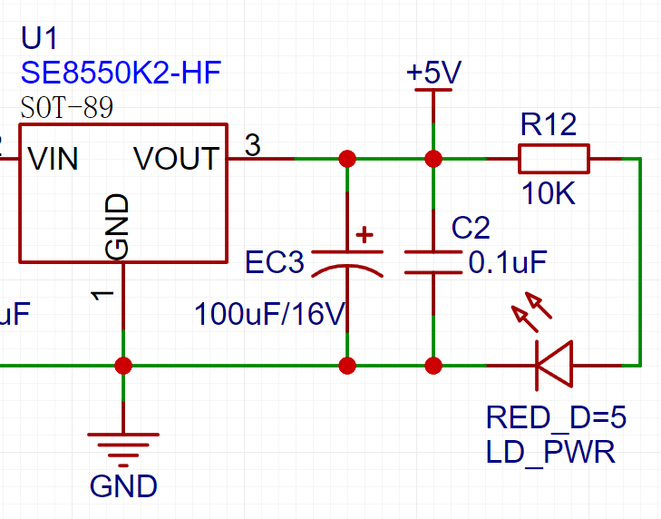
LD_PWR is the power working indicator

. Since the chip I/O often has a sinking current capability greater than a pull-up current capability, LED1 is designed to be I/O low-level active (on).
To reduce the current consumption of the LED, some LED brightness is sacrificed, the number of component parameters is reduced, and the current-limiting resistor for the LED is selected as 10K.
7. Button Circuit Design:

There are various design methods for the button control circuit. Thanks to the fact that the CW32's I/O port can be configured with pull-up and pull-down resistors internally, the button control circuit on the outside of the chip does not need to be configured. One end of the button is connected to the MCU's I/O, and the other end is grounded. When the button is pressed, the I/O is pulled low.


 京公网安备 11010802033920号

 AME8501BEFVDF42


